• Nvis Technology
  • Nvis Technology
  • Nvis Technology
  • Nvis Technology
  • Nvis Technology
  • Nvis Technology
Nvis Technology

Head Office

141-A, Electronic complex, Pardesipura,Indore - 452010 India

Phone: +91 73899 00887 , +91 98932 70303

Email:info@nvistech.com

Request a Quote

Looking for a quality and affordable builder for your next project?


    Nvis Technology

    Toll Free

    +91 73899 00887

    We are happy to meet you during our working hours. Please make an appointment.

    • Monday-Saturday: 9:00 AM - 5:30 PM (IST)
    • Sunday: Closed

    LCR Meter Working Principle: How Inductance, Capacitance & Resistance Are Measured

    TL;DR –

    • This blog is written for electronics students, engineers, lab technicians, manufacturers, educators, and repair professionals who need accurate measurement of inductance, capacitance, and resistance in real-world applications.
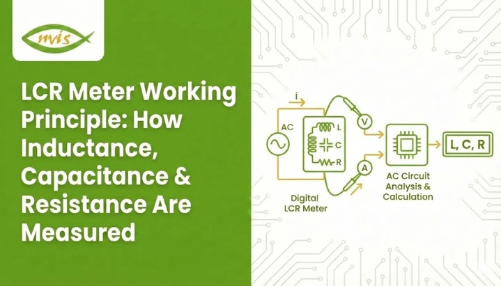
    • An LCR meter measures L, C, and R by applying a known AC test signal and analyzing impedance, voltage, current, and phase angle instead of relying on simple DC measurement.
    • The lcr meter working principle is based on impedance analysis, where resistance and reactance (from inductance or capacitance) are separated using phase relationships.
    • By detecting whether current leads, lags, or stays in phase with voltage, the meter accurately identifies and calculates capacitance, inductance, or resistance values.
    • The digital LCR meter working principle improves accuracy and speed through digital signal processing, auto-ranging, and frequency selection, making it ideal for modern labs, R&D, and quality control.

    Related Blogs –


    An LCR meter is a sensitive instrument used to measure inductance (L), capacitance (C), and resistance (R) by applying an AC test signal and analyzing impedance, phase angle, voltage, and current. Understanding the LCR meter working principle enables engineers, technicians, students, and manufacturers to obtain accurate component measurements for testing, design, quality control, and troubleshooting. Precision is important whether you are testing a capacitor on a PCB, checking an inductor in a power supply, or verifying resistor tolerances in a production process.

    A LCR meter is a type of meter created to measure passive components with significantly higher precision than any ordinary multimeter. Although a multimeter can measure the value of resistance and approximately determine the value of capacitance, it cannot analyze frequency-dependent behavior or phase relationships, both of which are required of inductors and capacitors.

    What Does an LCR Meter Measure?

    We will discuss the working principle but first, it would be appropriate to take a quick review of the three parameters measured.

    Inductance (L)

    Resistance to varying currents in a magnetic field by storing energy in a component (usually a coil) is known as inductance. It is expressed in henries (H), and very frequency-dependent.

    Capacitance (C)

    The capacity of a component to store electrical energy in an electric field is called Capacitance. It is expressed in farads (F) and it depends on the frequency, temperature and dielectric material.

    Resistance (R)

    Resistance is the opposition to the flow of electric current and is expressed as ohms (Ω). Resistance is theoretically frequency-independent, in contrast to inductance and capacitance, but in practice, components exhibit parasitic effects.

    All three are measured on an LCR meter, which measures the behavior of a component when it is exposed to an AC signal.

    The LCR Meter Working Principle

    LCR meter working principle is based on measuring the impedance of a component when it is excited by a known AC test signal. Measuring the reaction of the component to this signal, that is, the value of both voltage and current, and the angle between them, the meter will precisely decide whether the component is a resistor, capacitor, or inductor, and compute its value.

    The principle of working of the LCR meter is impedance measurement which enables the instrument to analyze the response of a component to an alternating current (AC) signal.

    Impedance (Z) is the total opposition a circuit presents to alternating current. Unlike simple resistance in DC circuits, impedance consists of resistance (R) and reactance (X).

    • Resistance (R)
    • Reactance (X) from inductance or capacitance

    The fundamental relationship is:

    • Inductive reactance: XL = 2πfL
    • Capacitive reactance: XC = 1 / (2πfC)

    By applying a known AC signal and measuring:

    • Voltage (V)
    • Current (I)
    • Phase angle (θ) between them

    The LCR meter establishes whether the component is mostly a resistor, capacitor or inductor and calculates it.

    Nvis 9303T Digital LCR Meter – Overview

    The Nvis 9303T is a digital LCR meter designed for accurate measurement of passive electronic components like inductors (L), capacitors (C), and resistors (R). It’s typically used in quality control, incoming inspection of components, and automated test systems in industrial and laboratory environments. 

    Parameter

    Frequency

    Typical Range (example)

    Capacitance (C)

    1 kHz

    0.1 pF – 9999.9 pF


    10 kHz

    0.01 pF – 999.99 pF

    Inductance (L)

    1 kHz

    0.1 pH – 9999.9 H


    10 kHz

    0.01 pH – 999.99 H

    Dissipation / Quality

    All

    D: 0.0001 – 9.999, Q: 0.0001 – 9999


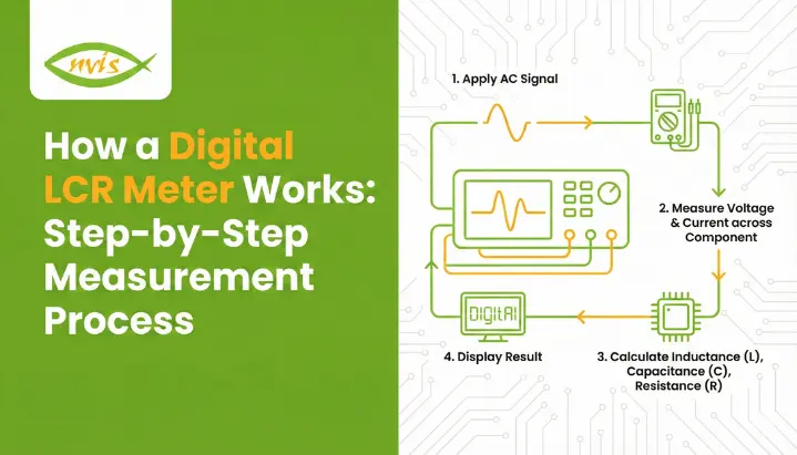
    How an LCR Meter Works: Step-by-Step

    When the lcr meter working process is divided into a logical sequence the process becomes much clearer. Each step is based on the LCR meter working principle of AC impedance measurement and phase analysis.

    1 AC Signal Generation

    The LCR meter generates a stable AC test signal using an internal oscillator. Common test frequencies include:

    • 100 Hz
    • 120 Hz
    • 1 kHz
    • 10 kHz
      Some advanced meters offer selectable or automatic frequency ranges.

    2 Applying the Test Signal to the Component

    The component under test (DUT) is connected using:

    • Two-terminal method (basic measurements)
    • Four-terminal (Kelvin) method for higher accuracy

    The four-terminal method eliminates errors caused by lead resistance and contact impedance.

    3 Measuring Voltage and Current

    Precision circuits inside the meter measure the voltage across and current through the component. These measurements form the basis of impedance calculation.

    4 Phase Angle Detection

    The phase difference between voltage and current reveals the component type:

    • 0° phase shift – Pure resistance
    • Current leads voltage – Capacitive behavior
    • Current lags voltage – Inductive behavior

    5 Parameter Calculation and Display

    Using digital signal processing, the meter calculates L, C, or R and displays the value on the screen, often along with:

    • Quality factor (Q)
    • Dissipation factor (D)
    • Equivalent series resistance (ESR)

    How Inductance, Capacitance & Resistance Are Measured

    An LCR meter is an inductance, capacitance, and resistance meter that uses the same basic principle, which is the analysis of AC impedance, but presents the results differently, based on the behavior of the component to the signal applied to it. In this section, the extracting principle of each parameter is detailed according to the lcr meter working principle.

    How Resistance (R) Is Measured

    When a purely resistive component is tested:

    • Voltage and current remain in phase (0° phase angle)
    • There is no reactive component (no energy storage)
    • Impedance is equal to resistance

    The LCR meter calculates resistance using:

    • R = V / I

    The meter uses an AC signal even in measuring resistance. This enables it to sense parasitic inductance or capacitance which a DC multimeter would not, and makes the measurement more realistic of actual parts.

    How Capacitance (C) Is Measured

    For capacitors, the current leads the voltage, creating a negative phase angle.

    Measurement process:

    • The meter applies a known AC frequency
    • It measures voltage, current, and phase angle
    • Capacitive reactance is calculated:
      • XC = 1 / (2πfC)

    From this relationship, the meter computes capacitance:

    • C = 1 / (2πfXC)

    Since the capacitance depends on the frequency and dielectric losses, the LCR meters can be configured to use realistic and application relevant frequencies (usually 100 Hz or 1 kHz).

    How Inductance (L) Is Measured

    For inductors, the current lags behind the voltage, producing a positive phase angle.

    Measurement process:

    • The AC signal causes energy storage in a magnetic field
    • Inductive reactance is calculated:
      • XL = 2πfL

    The meter then determines inductance:

    • L = XL / (2πf)

    Higher test frequencies are often used to improve sensitivity, especially for small inductance values.

    Why This Measurement Method Matters

    By gauging the behavior of a component under AC conditions, an LCR meter provides:

    • More realistic values than DC testing
    • Higher accuracy for frequency-sensitive components
    • Reliable data for quality control, testing, and design

    Inductance, capacitance, and resistance are measured by observing how voltage and current interact under AC excitation, making the LCR meter an essential tool for precise electronic component analysis.

    Accuracy Factors in LCR Measurement

    Even the best LCR meter requires proper usage to achieve accurate results.

    Common Influencing Factors

    • Test lead length and quality
    • Stray capacitance and inductance
    • Component temperature
    • Calibration status

    High-end meters include open, short, and load compensation to eliminate systematic errors.

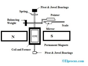
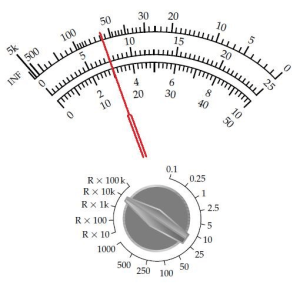
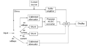
    Analog vs Digital LCR Meter Working

    Feature

    Analog LCR Meter

    Digital LCR Meter

    Accuracy

    Moderate

    High

    Ease of use

    Manual balancing

    Automatic

    Measurement speed

    Slow

    Fast

    Data display

    Scale-based

    Numeric + parameters

    Modern usage

    Limited

    Industry standard

    Due to efficiency and precision, digital models dominate today’s laboratories.

    Conclusion

    The working principle of an LCR meter is based on a simple yet powerful concept, which involves using a known AC signal and observing the response of a component. Through impedance and phase relation measurements, an LCR meter can accurately measure inductance, capacitance, and resistance, which are important parameters in modern electronics.

    Understanding the principles of lcr meter working is not only going to enhance the accuracy of measurements, but also assist the user to identify the correct instrument to use, prevent certain mistakes, and analyze the results properly. With the further development of electronics, tthe digital LCR meter working principle enables faster, smarter, and more reliable component testing of components in education, industry and research.

    FAQs

    An LCR meter is a device that uses a known AC test signal applied to a component and measures the impedance of the component which is the voltage, current and the phase angle. Based on these values, the meter determines whether the component behaves as a resistor, capacitor, or inductor and calculates its precise value.

    Inductance and capacitance are its frequency-dependents that cannot be accurately measured by DC. The AC signal enables the LCR meter to measure reactance and phase shift that is needed to calculate the values of L and C.

    The series mode applies in cases where resistive losses are the most important (usually when the inductance is small and the capacitors of interest are very low-value), whereas the parallel mode is used where leakage losses or parallel resistance are important (large capacitors).

    Since reactance varies with frequency, capacitor and inductor impedance vary with the test frequency. The loss and material properties also change with the frequency, which interferes with the measurement outcomes.

    Yes. An LCR meter measures resistance under AC impedance, and therefore is able to take into consideration parasitic inductance and capacitance which cannot be sensed in a DC multimeter, leading to further refined measurements of actual components.

    Tags: digital lcr meter working principle, lcr meter working, lcr meter working principle

    Gauss Meter Is Used to Measure What? Magnetic Field Explained

    TL;DR –

    • This blog is written for electronics engineers, technicians, students, educators, R&D professionals, and quality control teams who need a clear understanding of magnetic field measurement.
    • It explains what a gauss meter is used to measure, focusing on magnetic field strength and magnetic flux density in gauss or tesla units.
    • The blog breaks down gauss meter measurement principles, including how sensors and probes detect static (DC) and alternating (AC) magnetic fields.
    • It highlights real-world applications of gauss meters in electronics testing, magnet manufacturing, automotive systems, medical equipment, and research labs.
    • The blog emphasizes accuracy, proper usage, and correct selection of gauss meters to ensure reliable, safe, and consistent magnetic field measurements.

    Magnetic fields play a critical role in modern technology, even though they are invisible to the human eye. From smartphones, electric vehicles, and power supplies to medical equipment and industrial machinery, magnetic fields influence performance, safety, and reliability. Measuring these fields accurately is essential to ensure devices work as intended and comply with design standards.

    This is where a gauss meter becomes important. Many engineers, students, and technicians ask a simple but fundamental question: gauss meter is used to measure The answer lies in understanding magnetic field strength and how it affects electrical and electronic systems.

    In this detailed guide, we will explain gauss meter measurement, what a gauss meter is used to measure, how it works, its types, applications, and best practices. By the end of this blog, you will have a clear, practical understanding of magnetic field measurement and why gauss meters are indispensable tools across industries.


    Related Blogs


    What Is a Gauss Meter?

    A Gauss meter is a scientific and electronic measurement instrument used to measure the strength and direction of a magnetic field. It measures magnetic flux density, typically expressed in Gauss (G) or Tesla (T), where 1 Tesla = 10,000 Gauss.

    Gauss meters are widely used in electronics labs, physics experiments, industrial testing, research, and education to analyze magnetic fields generated by permanent magnets, electromagnets, motors, transformers, and electronic components.

    The unit of measurement used by a gauss meter is typically gauss (G) or tesla (T):

    • 1 tesla = 10,000 gauss
    • Gauss is commonly used for lower-strength magnetic fields
    • Tesla is used for very strong magnetic fields, such as in MRI systems

    When people ask gauss meter is used to measure what, the most accurate answer is:

    A gauss meter is used to measure the strength and sometimes the direction of magnetic fields.

    Understanding Magnetic Fields Measurement  

    A magnetic field is an invisible force field that surrounds magnets, electric currents, and changing electric fields. It represents the region where magnetic forces can be detected and measured. Magnetic fields are fundamental to how many electrical and electronic systems operate, from simple motors to advanced medical and industrial equipment.

    Magnetic fields are described by their strength and direction. Strength indicates how intense the field is at a given point, while direction shows the orientation of the magnetic force. These characteristics are commonly visualized using magnetic field lines, which emerge from the north pole of a magnet and enter the south pole. The closer the lines, the stronger the magnetic field.

    The key quantity used to describe magnetic field strength is magnetic flux density, measured in gauss (G) or tesla (T). This is precisely what instruments like gauss meters are designed to measure. Understanding magnetic fields and their behavior is essential for designing reliable electronics, ensuring safety, and maintaining consistent performance in real-world applications.

    What Does a Gauss Meter Measure?

    A gauss meter is a precision measurement instrument used to evaluate magnetic fields with high accuracy. It plays a critical role in electronics, electrical engineering, physics laboratories, manufacturing, and quality control, where understanding magnetic behavior is essential for performance, safety, and reliability.

    A gauss meter is designed to measure the strength and characteristics of a magnetic field. Its primary measurements include:

    • Magnetic field strength
      This indicates how strong the magnetic field is at a specific point. It is typically expressed in Gauss (G) or Tesla (T) and helps determine whether a magnetic source meets required specifications.
    • Magnetic flux density
      Magnetic flux density describes how concentrated the magnetic field lines are in a given area. This measurement is especially important in applications involving motors, transformers, and magnetic sensors, where field uniformity directly affects efficiency and performance.
    • Field polarity and direction
      Many modern gauss meters can identify whether the magnetic field is north or south oriented and detect its direction. This is crucial when aligning magnets, testing assemblies, or verifying correct installation in electromechanical systems.

    Static and Dynamic Magnetic Fields

    Depending on its design and sensor type, a gauss meter can measure both:

    • Static (DC) magnetic fields – typically produced by permanent magnets
    • Alternating (AC) magnetic fields – generated by coils, motors, and power systems

    Understanding whether the magnetic field is AC or DC is crucial for accurate gauss meter measurement and correct data interpretation, especially in diagnostics, quality control, and research applications.

    How Gauss Meter Measurement Works

    A gauss meter measures magnetic fields by detecting how a magnetic force influences an electronic sensor and converting that influence into a readable numerical value. The measurement process is designed to be precise, repeatable, and suitable for both laboratory and industrial environments.

    Sensor Principle

    Most modern gauss meters operate using a magnetic field sensor placed inside a probe. When the probe is exposed to a magnetic field, the sensor converts the magnetic signal into an electrical signal.

    Probe Orientation

    One of the most important factors in accurate gauss meter measurement is probe orientation. Magnetic fields have direction, and incorrect alignment can lead to inaccurate readings. Advanced gauss meters may use multi-axis probes to capture field strength in different directions simultaneously.

    Display and Output

    Digital gauss meters provide:

    • Instant readings on an LCD screen
    • High resolution and repeatability
    • Data logging and computer connectivity in advanced models

    Types of Gauss Meters

    Different applications demand different levels of accuracy, functionality, and field analysis. Understanding the types of gauss meters helps engineers, technicians, educators, and students select the right instrument for accurate magnetic field measurement.

    • Digital Gauss Meters

    Offer high accuracy, fast response, and an easy-to-read digital display. Widely used in laboratories, R&D, and industrial testing.

    • Analog Gauss Meters

    Based on older technology with limited accuracy. Mostly replaced by digital gauss meters in modern applications.

    • Single-Axis Gauss Meters

    Measure magnetic fields in one direction. Suitable for basic and routine magnetic field testing.

    • Three-Axis Gauss Meters

    Measure magnetic fields in X, Y, and Z directions, making them ideal for complex and non-uniform magnetic field environments.

    Why Accuracy Is Critical in Gauss Meter Measurement

    Accurate gauss meter measurement is essential because even minor errors in magnetic field readings can lead to serious technical and safety problems. Magnetic fields directly influence how electronic and electromechanical systems behave, and incorrect measurements can compromise performance, reliability, and compliance.

    In electronics, excess or uncontrolled magnetic fields can:

    • Interfere with sensitive circuits and signal integrity
    • Cause sensor malfunction or inaccurate feedback
    • Lead to overheating, efficiency loss, or premature component failure

    Precise gauss meter measurements help engineers identify and control these risks during design, testing, and quality assurance.

    Importance of Precision in Magnetic Field Measurement

    Accurate readings ensure:

    • Reliable and consistent product performance
    • Safety of equipment and users, particularly in high-power or industrial environments
    • Compliance with design specifications and industry standards, reducing rework and failures

    To maintain high accuracy, gauss meters must be properly calibrated, used with correct probe alignment, and operated under recommended measurement conditions. This disciplined approach ensures dependable magnetic field data across laboratories, manufacturing floors, and research environments.

    Gauss Meter vs Other Magnetic Field Measurement Tools

    Different tools are used to measure magnetic fields, but each serves a specific purpose. Understanding how a gauss meter compares with other magnetic field measurement instruments helps in selecting the right tool for the job.

    Tool

    What It Measures

    Best For

    Key Characteristics

    Gauss Meter

    Magnetic field strength in Gauss or Tesla

    Permanent magnets, motors, transformers, electronic assemblies

    High accuracy, fast response, ideal for lab and industrial testing

    Teslameter

    Magnetic field strength in Tesla

    Strong magnetic fields, research, high-power applications

    Similar to gauss meter but optimized for high-field measurements

    Search Coil Sensors

    Changing (AC) magnetic fields

    Dynamic magnetic field analysis

    Works on electromagnetic induction; not suitable for static (DC) fields

    Fluxgate Magnetometers

    Very weak magnetic fields

    Geophysics, navigation, Earth’s magnetic field studies

    Extremely sensitive; not commonly used for routine electronics testing


    Conclusion

    To summarize, a gauss meter is used to measure magnetic field strength or magnetic field, providing critical insights into how magnetic fields behave in real-world systems. From electronics and automotive engineering to healthcare and research, gauss meter measurement ensures accuracy, safety, and performance.

    Understanding what a gauss meter measures, how it works, and how to use it correctly empowers engineers, technicians, and students to make informed decisions and reliable measurements. As technology continues to advance, the gauss meter will remain a fundamental tool for exploring and controlling the invisible force of magnetism.


    FAQs

    A gauss meter is used to measure the strength of a magnetic field, specifically magnetic.It shows how strong a magnetic field is at a particular point, usually in gauss or tesla units.

    Gauss meter measurement means checking how strong a magnetic field is around a magnet, electrical device, or component, helping ensure safe operation and correct performance.

    Yes, many modern gauss meters can measure both DC magnetic fields from permanent magnets and AC magnetic fields produced by coils, motors, and power systems.

    Gauss meter measurement is widely used in electronics testing, magnet manufacturing, automotive and EV systems, medical equipment monitoring, and research laboratories.

    A gauss meter helps detect unwanted or excessive magnetic fields that can interfere with electronic circuits, sensors, and components, ensuring reliability and safety.

    Tags: gauss meter is used to measure, gauss meter measurement

    How a Digital LCR Meter Works: Step-by-Step Measurement Process

    TL;DR –

    • This blog is written for electronics engineers, technicians, students, educators, and R&D professionals who want a clear, practical understanding of how a digital LCR meter works.
    • The blog explains what a digital LCR meter is and why it is essential for accurate measurement of inductance, capacitance, and resistance.
    • It breaks down the digital LCR meter working principle, showing how AC signals, phase measurement, and impedance calculation are used.
    • The blog covers measurement modes, test frequency importance, and common mistakes to ensure accurate results.
    • It highlights real-world applications and advantages of using an LCR meter digital instrument in labs, manufacturing, and education.


    Related Blogs

    In modern electronics, precision in component measurement is critical. The reliability and performance of a final product is dependent upon the correct knowledge of the precise electrical properties of components, whether you are designing a power supply, debugging a circuit, validating a prototype, or performing quality control on a production line. A digital LCR meter becomes a very crucial tool in this.

    In contrast to simple types of multimeters, which simply give approximate values of the resistance, an LCR meter digital instrument is intended to accurately measure the inductance (L), capacitance (C), and resistance (R) under controlled test circumstances. To fully appreciate its value, it is important to understand the digital LCR meter working principle and its step-by-step measurement process.

    This article explains the detailed operation of a digital LCR meter. including the signal formation inside a meter and the display of the measurement values in digital form in the end.


    What Is a Digital LCR Meter?

    A digital LCR meter is a special electronic measuring device used to measure the electrical properties of passive electronic components, like resistors, capacitors and inductors, with high precision. Contrary to the simple multimeters which usually impose DC voltage and can provide only a limited amount of information, digital LCR meter applies a carefully regulated AC test signal and measures how a component behaves under real operating conditions and frequency dependent factors.

    The instrument is capable of measuring the electrical properties of a component by measuring the voltage, current, and phase relationship of the current applied as an AC signal. This is particularly handy in a digital LCR meter when accurate and repeatable measurements are important e.g. circuit design, component verification, quality control and research and development.

    The three basic parameters that are measured using the instrument are called LCR:

    • L – Inductance: The ability of a component, typically a coil, to store energy in a magnetic field when current flows through it.
    • C – Capacitance: The ability of a component to store electrical energy in an electric field between conductors separated by an insulating material.
    • R – Resistance: The opposition offered by a material or component to the flow of electric current, resulting in energy dissipation as heat.

    An LCR meter can give an accurate and understandable reading of the electronic components by digitally processing these values to help engineers, technicians and students of electronic components understand and assess the electronic component.


    Why Are Digital LCR Meters Important in Electronics?

    Digital LCR meters play a vital role in electronics since they ensure accurate and repeatable measurements of passive components including resistors, capacitors as well as inductors. A digital LCR meter, in comparison to basic multimeters, applies an AC test signal to the component under measurement, providing measurements of component behavior in realistic operating conditions, and leads to more meaningful and accurate values.

    Even minor changes in the values of components in circuit design and development can impact on performance, efficiency and stability. A digital instrument of an LCR meter assists the engineer in checking the real component parameters and tolerance and to comprehend parasitic effects which might affect high-frequency or delicate circuits. The accuracy is needed especially in research, prototyping and validation phases.

    Digital LCR meters have also found a wide range of applications in manufacturing and quality control. They enable rapid and reproducible testing to assure component uniformity, screen defects and preserve quality of products. The vivid digital display and multi-parameter readings are more advantageous in education and troubleshooting: it is simpler to examine elements and identify problems related to the circuit. All in all, the worth of digital LCR meter working is that it provides reliable data which can be relied upon in order to design and test electronically.

    • Test components at specific frequencies
    • Detect faulty or degraded parts
    • Compare measured values with design specifications
    • Ensure consistency in manufacturing

    Because of this, digital LCR meters are widely used in R&D laboratories, educational institutions, service centers, and electronics manufacturing facilities.


    How a Digital LCR Meter Works?

    A digital LCR meter is a meter which measures the impedance of a component with a controlled AC test signal instead of a simple DC voltage. This method can give the instrument the chance to test the behavior of a component in the actual operating environment that is important in measuring inductance, capacitance, and resistance accurately.

    During operation, the meter sends a given AC signal through a component under test at a given frequency with a given amplitude. It then measures the voltage across the component and the current through the component. The LCR meter digital instrument measures the magnitude and phase difference of a voltage and current to establish the type of response of the component, which is resistive, capacitive, or inductive.

    Digital signal processing is used to change the measured values into impedance values and mathematically decompose them into resistance (R), inductance (L), or capacitance (C). The resulting calculated values are then presented precisely on the screen, and in many cases with other values like impedance, phase angle, quality factor or the dissipation factor. This is what makes this digital LCR meter a reliable instrument to test electronics, test a design, or ensure quality control because of a specific and repeatable working process.

    Here is a clear, step-by-step explanation of how an LCR meter digital instrument works:


    1. Application of AC Test Signal

    The digital LCR meter creates an accurate AC signal at a desired frequency and passes it to the component under test. This frequency can also be modified regularly to suit real circuit conditions.


    2. Measurement of Voltage and Current

    The meter measures the current and voltage across the component in which the signal is passing through as the signal moves through the component. These two values are imperative in calculation of impedance.


    3. Phase Angle Detection

    The meter identifies the voltage and current phase difference. It is the phase relationship that defines the component as a resistor, capacitor or inductive.


    4. Impedance Calculation

    Based on the measured value of the voltage, current, and the phase angle, the digital LCR meter then calculates the impedance of the component. Impedance consists of resistive components and reactive components.


    5. Extraction of L, C, or R Values

    Depending on the impedance measurements and the mode of measurement chosen, the instrument determines values of inductance, capacitance or resistance in a high precision manner.


    Step-by-Step Measurement Process of a Digital LCR Meter

    Let us now walk through the step-by-step digital LCR meter working process, from component connection to result display.

    Step 1: Connecting the Component Under Test (DUT)

    The initial one is to couple the component with the LCR meter terminals. Simple measurements can be done with simple test leads. In high precision work with typically low resistance or low inductance parts, Kelvin connections are made to avoid lead resistance errors.

    Open-circuit and short-circuit compensation can be carried out before measurement in order to increase accuracy.


    Step 2: Applying the AC Test Signal

    After connecting the component, a known AC test signal is applied with the help of the digital LCR meter. This signal has:

    • A constant frequency or frequency that can be chosen.
    • Certain voltage or current level.

    Frequency: This is an important decision since different components respond differently to dissimilar frequencies. As a case example, capacitors are frequently tested at 1 kHz, whereas inductors can be tested at lower frequencies.


    Step 3: Measuring Voltage and Current

    As the AC signal passes through the component, the meter simultaneously measures:

    • The voltage across the DUT
    • The current flowing through it

    These two values form the foundation of impedance calculation.


    Step 4: Detecting Phase Difference

    One of the most important steps in digital LCR meter working is phase detection. The meter determines the phase angle between voltage and current:

    • 0° phase difference: Pure resistance
    • Current leads voltage: Capacitive behavior
    • Current lags voltage: Inductive behavior

    This phase information allows the meter to separate resistance from reactance.

    Step 5: Calculating Impedance (Z)

    Using the measured voltage (V), current (I), and phase angle (θ), the meter calculates impedance:

    Z=VIZ = \frac{V}{I}Z=IV​

    It then mathematically resolves impedance into its resistive and reactive components.

    Measurement Modes in an LCR Meter Digital Instrument

    An LCR meter digital meter provides various measurement modes so as to properly represent the electrical characteristics of various components. To get accurate results the mode must be chosen, since real world components have either series or parallel loss characteristics depending upon their value and construction.

    Series Mode

    A series mode is applied when a component acts as a series combination of both resistance and inductance (R L) or capacitance (R C). This mode is conventionally favored when the losses in series are more important, e.g. small resistors, low-capacitance capacitors, low-inductance coils, etc.

    Parallel Mode

    Parallel mode can be used when the leakage or dielectric loss characteristics of a device can be modeled in parallel, such as with capacitors and high-value inductances. The component in this mode is modelled to act as a parallel network, which gives more precise results when the component is of high impedance

    Auto Mode

    At auto mode, the digital LCR meter automatically checks the impedance of the component and automatically chooses either the series mode or parallel mode. This makes measurements easier, besides allowing maximum accuracy without the manual selection of mode.

    Importance of Test Frequency in Digital LCR Meter Working

    The test frequency is also a key factor in the digital LCR meter functioning, since it directly influences the measurement accuracy and relevance. Passive components do not act perfectly at all frequencies, but rather the electrical behaviour of a passive component varies with frequency of the AC signal applied to it.

    • Dielectric losses and parasitic effects usually cause different values of the capacitance of the capacitors at low and high frequencies.
    • At lower frequencies, inductors can become core-saturated and at higher frequencies may exhibit resonance effects and change their apparent inductance.

    A digital LCR meter provides an option to users to choose the right frequency of the test, which ensures that components are tested under the conditions that are close to their real-life applications. The possibility renders LCR meter digital instrument a necessity to characterize components accurately, design circuits reliably and to be able to control quality.

    Applications of Digital LCR Meters

    Digital LCR meters have been critical instruments in a broad spectrum of industries since they are precise and flexible in measuring passive components. It is commonly used in:

    • Electronics labs Component testing to confirm inductance, capacitance and resistance in circuit design and prototyping.
    • During manufacturing, quality assurance whereby the components used are of particular tolerances prior to assembly.
    • Failure analysis and repair operations, assisting technicians to locate faulty or damaged parts within a short time.
    • Experiments and training in education: students are taught effective methods of measurement and component behavior.
    • Development of new circuits, to facilitate accurate testing of the components in controlled test work.

    They are critical in the working world because of their capacity to deliver consistent and precise outcomes.

    Advantages of Using a Digital LCR Meter

    A digital LCR meter has a number of benefits compared to the older component measurement techniques, and it is an essential tool in the electronics testing and analysis of the present day.

    • High accuracy and resolution, ensuring reliable measurements in measuring inductance, capacitance and resistance.
    • Quick and repeatable measurements, which enhance productivity in the laboratory and manufacturing setup.
    • Several parameters in one test, e.g. impedance, ESR, quality factor, and dissipation factor.
    • Digital display, with user friendly results that are easy to read with minimum set up requirements.
    • Automation and data logging enabled so as to integrate with test systems to allow analysis and record keeping.

    These advantages make them better than basic multimeters in testing the components.

    Conclusion

    The knowledge of the functionality of a digital LCR meter can help in enlightening the reasons as to why it is considered a very imperative tool in testing electronics. With the use of a controlled AC signal, the measurement of voltage, current, and phase difference and the digital processing of the findings, an LCR meter digital meter can provide accurate values of resistance, capacitance, and inductance.

    Since the digital LCR meter working process comprises step-by-step signal application up to advanced digital computation, the correctness, repeatability, and application-relevant measurement is ensured. Regardless of whether you are an engineer or a student or a technician, it is imperative to know how to operate a digital LCR meter to build reliable and high-performance electronic systems

    FAQs

     A digital LCR meter is used to measure inductance, capacitance, and resistance of electronic components with high accuracy. It applies an AC test signal to analyze real operating behavior, making it ideal for labs, manufacturing, R&D, and educational testing.

     Unlike a multimeter that mainly uses DC measurement, a digital LCR meter uses AC signals and phase analysis. This allows it to measure L, C, and R accurately at different frequencies, giving more realistic and reliable component values.

     Components behave differently at different frequencies. Capacitors change value with frequency, and inductors may resonate or saturate. A digital LCR meter allows frequency selection to ensure measurements match real application conditions.

     Series mode is used for low-value components where series losses dominate, while parallel mode suits high-value components with leakage losses. Auto mode selects the best option automatically based on impedance for accurate results.

     No, components should be tested outside the circuit. In-circuit measurements can give incorrect readings due to parallel paths and other components affecting impedance, leading to inaccurate LCR values.

    Power Meter in Microwave Systems: Why Accurate Power Measurement Matters

    • A power meter in microwave systems is essential for accurate, reliable power measurement at high frequencies.
    • Microwave power meters directly measure RF and microwave power, making them more reliable than voltage-based methods.
    • Accuracy affects system performance, safety, efficiency, and regulatory compliance.
    • Different sensor types (thermal, diode, peak) suit different applications.
    • Proper setup, calibration, and handling are critical to avoid measurement errors.

    In high-frequency applications, accurate measurements are essential to every successful engineering system. In microwave and RF design, even minor measurement errors can lead to degraded performance, safety risks, and costly design mistakes. It is due to this reason that the power meter used in the microwave systems is such a critical factor in the laboratories, production floors, and field installations.

    The microwave power meter is among the most reliable tools in the measurement of microwave activities, whether it is in validating the transmitter output or in terms of regulatory compliance. This article provides a professional explanation of the working mechanism of a  power meter microwave system, the importance of accuracy, and how one of the engineers can get reliable results when using a power meter in the real world.

    Understanding Power Measurement in Microwave Systems

    Microwave systems typically operate at frequencies above 300 MHz and extend into the gigahertz (GHz) range. At such frequencies, low-frequency methods of measurement are no longer adequate. Changes in signal behavior, growth in losses and parasitic effects gain relevance.

    A microwave power meter has been made to cope with these challenges. It quantifies the actual power of a microwave source, amplifier or transmitter and gives the engineer one straightforward and reliable parameter with which to assess the performance of the system.

    Contrary to the measurement of voltages or currents, power is one of the most stable and repeatable quantities in high-frequency microwave systems, and the microwave power meter is a staple of RF test systems.

    What Is a Microwave Power Meter?

    A microwave power meter is an instrument used to measure the average or peak power of microwave signals. It typically consists of two main parts:

    • A power sensor, which interacts directly with the microwave signal
    • A display or processing unit, which converts the sensor output into a readable power value

    Depending on the design of the sensor, a power meter microwave system has the potential to measure power over a wide range of frequencies extending between a few megahertz and tens of gigahertz.

    Since the measurement of power is independent of the shape of the waveform or complexity of the modulation of digital signals, the power meter of microwave systems is highly applicable both to simple continuous-wave (CW) signals and more complex digitally modulated signals.

    Why Accurate Power Measurement Matters?

    1. System Performance and Efficiency

    In the microwave systems, coverage, signal quality, and efficiency are directly proportional to the output power. A faulty result of a microwave power meter can make engineers think that a system is working when it is not.

    A power underestimation may lead to inadequate performance of the system whereas overestimation can cause system overheating, distortion or breaking of components. The correct power meter microwave system is important for accurate power measurements to ensure that amplifiers, transmitters and antennas are working according to their specifications.

    2. Safety in High-Power Microwave Applications

    High-power microwave systems are widely used in radar, satellite communication, and industrial heating applications. The wrong power values can be life-threatening to the equipment and human life.

    A trustworthy power meter in a microwave system will assist avoid unnecessary overexposure, destruction of components and unsafe operation environments, as it will give assurance of measured power.

    3. Compliance with Standards and Regulations

    Several wireless and microwave networks are required to meet stringent regulatory restrictions on the power radiated. The government defines the maximum allowable power to prevent interference and allow safe operation.

    It is necessary to show compliance by using a calibrated microwave power meter. Certification and approval processes can be considered to be unreliable and dangerous without proper power measurements.

    Working Principle of a Power Meter in Microwave Systems

    The working principle of a power meter within the microwave systems is grounded in the fact that the conversion of the high frequency microwave power energy into something that is measurable and traceable is done accurately. Microwave signals cannot be accurately measured using conventional voltmeters or ammeters, making direct power measurement essential at high frequencies.Rather, a microwave power meter is used to measure the actual power picked up by the microwave signal, and thus it is one of the most reliable measurements in RF and microwave engineering.

    In this effort, a basic power meter microwave system will be composed of a power sensor and a display unit or a processing unit. They combine to convert the microwave energy to useful power readings, usually in the form of watts or dBm.

    Basic Measurement Concept

    1. The microwave signal is applied to a power sensor
    2. The sensor absorbs part or all of the microwave energy
    3. This energy is converted into heat or an electrical signal
    4. The meter processes this signal and displays power in watts or dBm

    Because the power meter in microwave systems measures actual energy rather than inferred values, it provides high accuracy across wide frequency ranges.

    Types of Microwave Power Meters

    Microwave systems are used with a high level of frequencies, power and signal formats. Different kinds of microwave power meter have been developed in order to cover these diverse needs. None of the types is universal, as each of them relies on a different principle of measurement and is designed to be applied in a particular application. Knowledge of these kinds can assist engineers to choose the appropriate power meter in the microwave systems so as to make precise and dependable measurements.

    Thermal Power Meters

    • Measure power by detecting heat generated by microwave energy
    • Known for excellent accuracy and stability
    • Ideal for calibration and reference measurements

    Thermal sensors make the power meter microwave extremely reliable for average power measurements.

    Diode Detector Power Meters

    • Use semiconductor diodes to detect microwave signals
    • Faster response time than thermal sensors
    • Suitable for low-power and modulated signals

    These sensors are widely used in modern power meters in microwave instruments due to their versatility.

    Peak Power Meters

    • Designed to capture fast, high-power pulses
    • Essential for radar and pulsed microwave systems
    • Measure peak, average, and pulse parameters


    Components of a Microwave Power Measurement Setup

    The power meter alone does not guarantee reliable microwave power measurement.Proper connection of the components and their selection are the keys to the right results. Every component of the system has a direct effect on the quality and consistency of measurements as well as their safety. To make good use of a power meter in microwave systems, it is important to understand these components.

    A complete power meter microwave setup typically includes:

    • Power sensor: The most critical component determining accuracy
    • Meter or display unit: Processes and displays measured power
    • Interconnects: Coaxial cables or waveguides for signal delivery

    Every component affects the overall accuracy of the microwave power meter, making careful selection and handling essential.

    Factors Affecting Accuracy in Microwave Power Measurement

    Measurement of microwave power is very critical to assure proper performance, safety, and compliance with regulations of a system. Although a power meter of high quality appears in the microwave systems, there are a number of external and internal factors that may affect the accuracy of measurements. The knowledge of these considerations assists the engineers to reduce mistakes and to get reliable results of a microwave power meter.

    Even the most precise microwave power meter can produce inaccurate results if key influencing factors are ignored.

    a) Frequency Response

    Sensors have specified frequency ranges. Using a sensor outside its rated band can introduce significant errors.

    b) Mismatch and VSWR

    Impedance mismatches between the source and sensor cause reflected power, reducing measurement accuracy. High-quality sensors are designed to minimize these effects.

    c) Temperature Effects

    Thermal drift can affect readings, especially in long-duration measurements. This is why stable environments and warm-up times are important for microwave power meter accuracy.

    D) Calibration Uncertainty

    Every power meter microwave system must be calibrated against traceable standards. Skipping calibration leads to unreliable data.

    Applications of Microwave Power Meters

    Microwave power meters are important tools where microwave and RF energy is produced, transmitted or measured. The power meter has become very common in microwave systems due to the repeatability and reliability of power which is one of the most reliable parameters at high frequencies. The following are the critical areas of application of a microwave power meter.

    The power meter microwave is used across a wide range of industries:

    Communication Systems

    • Cellular base stations
    • Satellite uplinks and downlinks
    • Microwave backhaul systems

    Radar and Defense

    • Transmitter power validation
    • Pulse power measurement
    • System diagnostics

    Research and Education

    • University laboratories
    • Microwave component characterization
    • Experimental RF systems

    Manufacturing and Production Testing

    • Quality assurance
    • End-of-line testing
    • Compliance verification

    In all these cases, the power meter in microwave systems ensures repeatability, reliability, and confidence in results.

    Common Mistakes to Avoid When Using a Microwave Power Meter

    A high-quality instrument may not give the correct result despite the instrument being of high quality unless the appropriate measurement practices are applied. The microwave power meter is not the cause of many of the errors in microwave testing, but improper setup, poor handling, or lack of understanding of the measurement limits. To a great extent, preventing the following widespread errors will help to enhance the accuracy, safety, and reliability of any power meter in microwave systems.

    Even experienced engineers can encounter errors when using a microwave power meter:

    • Selecting the wrong sensor for frequency or power level
    • Ignoring cable and connector losses
    • Overloading the sensor
    • Skipping warm-up and zeroing procedures

    Avoiding these mistakes significantly improves the reliability of power meter microwave measurements.

    Conclusion

    Precision in power measurement is not only a technical specification, but a base of performance in microwave engineering, safety and compliance.Microwave systems rely on power meters to provide a direct, reliable, and trusted method for gauging microwave signal power. in industries and applications.

    With the knowledge on how a microwave power meter operates, the factors influencing its precision and the proper use of the meter, engineers are able to know that their systems are functioning as they expected. The power meter microwave has also been one of the most critical equipment in the modern RF and microwave measurement, in a field where precision is a critical factor.

    Frequently Asked Questions (FAQs)

    1. What is a power meter in microwave systems?
      A power meter in microwave systems is an instrument used to measure the actual power of microwave and RF signals accurately, typically in watts or dBm.
    2. Why is a microwave power meter preferred over voltage measurements?
      At microwave frequencies, voltage and current are difficult to measure directly. A microwave power meter provides stable, direct, and repeatable power measurements independent of waveform shape.
    3. What types of microwave power meters are commonly used?
      Common types include thermal power meters, diode detector power meters, and peak power meters, each designed for specific power levels and signal types.
    4. What affects the accuracy of a power meter microwave measurement?
      Accuracy is influenced by sensor frequency range, calibration, mismatch (VSWR), cable losses, temperature, and proper sensor selection.
    5. Where are microwave power meters used?
      Microwave power meters are widely used in wireless communication, radar, satellite systems, R&D labs, manufacturing, aerospace, and educational institutions.

    Related Blogs:

    How Analog and Digital Multimeters Work: Basic Working Principles


    • This blog targets students, technicians, and engineers learning electrical measurements.
    • A multimeter measures voltage, current, and resistance in electrical circuits.
    • Analog multimeters work on the PMMC principle using needle deflection.
    • Digital multimeters use ADCs and digital processing for high accuracy.
    • Digital multimeters dominate modern applications, while analog meters remain useful for learning and trend observation.

    The foundation of electrical and electronics engineering is the ability to measure electrical quantities accurately. The analog and digital multimeter is one of the tools you will always find in your toolbox, whether you are a student learning basic circuit principles, a technician troubleshooting a system, or an engineer verifying system performance.

    Despite the extensive use of digital technologies in the modern laboratories and field settings, the knowledge of the principles of work of an analog multimeter and a digital multimeter helps to gain a better idea of the working principles of electrical measurements and how they are measured, interpreted, and believed in.

    This paper describes the working principle of analog and digital multimeters, their internal mechanisms, main distinctions, and the conditions under which each of them is most appropriate.

    What Is a Multimeter?

    A multimeter is a flexible electrical measuring device that is utilized to measure various electrical parameters in a single device. It is among the most important tools in electrical and electronics work that is commonly used among students, technicians, engineers, and maintenance workers.

    At a basic level, a multimeter combines the functions of three instruments:

    • Voltmeter – measures electrical voltage (AC and DC)
    • Ammeter – measures electrical current
    • Ohmmeter – measures electrical resistance

    Modern multimeters can also measure additional parameters such as continuity, capacitance, frequency, temperature, and diode characteristics, depending on the model.

    Multimeters are available in two main types:

    • Analog multimeters, which use a moving needle and scale to display readings
    • Digital multimeters, which display measurements as precise numerical values on a screen

    Whether analog or digital, the primary purpose of a multimeter is to help users test, diagnose, and verify electrical circuits safely and accurately, making it a fundamental instrument in both learning environments and real-world applications.

    Basic Working Principle of an Analog Multimeter

    The fundamental mechanism of working of an analog multimeter is the Permanent Magnet Moving Coil (PMMC) mechanism. This principle transforms electrical quantity into mechanical movement which can be observed graphically on a scale.

    An analog multimeter operates on the Permanent Magnet Moving Coil (PMMC) principle. A force is created by passing electric current through a coil in a magnetic field which causes the coil and pointer attached to it to move.

    Electrical quantities can be measured because the deflection of the pointer is proportional to the current. The same mechanism is used to measure voltage using a series resistor, current using a shunt resistor, and resistance using an internal battery.

    A calibrated scale is used to read the reading and the reading gives a real-time and continuous reading of the value being measured.

    Basic Working Principle of a Digital Multimeter

    The principle of operation of a digital multimeter (DMM) is rooted in electronic signal processing and analog-to-digital conversion and analog-to-digital conversion. A digital multimeter, unlike an analog multimeter, does not need the movement of a mechanical aspect; this is because it measures the electrical activity and converts it to digital data which can be properly read on a screen.

    1. Input Signal Conditioning

    • The measured voltage, current, or resistance is first conditioned using resistors and protection circuits.
    • This ensures the signal is within a safe and measurable range.

    2. Analog-to-Digital Conversion (ADC)

    • The conditioned analog signal is converted into a digital value using an ADC.
    • This is the heart of the digital multimeter.

    3. Digital Processing

    • A microcontroller processes the digital data.
    • Mathematical calculations are performed to display the final measurement.

    4. Digital Display

    • The processed value is shown on an LCD or LED display as a precise numerical reading.

    How an Analog Multimeter Measures Different Quantities

    An analog multimeter operates on the Permanent Magnet Moving Coil (PMMC) principle to measure different electrical quantities but in measuring various electrical quantities. The instrument is able to measure voltage, current and resistance with the help of the change of internal circuit configuration using range selectors and resistors.

    Voltage Measurement

    • A high-value series resistor is added to limit current.
    • The voltage applied causes a proportional current through the coil, resulting in pointer deflection.

    Current Measurement

    • A low-resistance shunt is connected in parallel to handle higher currents safely.
    • Only a small fraction of the current flows through the moving coil.

    <h3class=”margin_top_10px”>Resistance Measurement

    • An internal battery supplies current.
    • Resistance is calculated based on how much current flows through the unknown resistor.
    • The scale is nonlinear, requiring careful reading.

    How a Digital Multimeter Measures Different Quantities?

    A digital multimeter (DMM) measures electrical quantities using electronic circuits, signal conditioning, and an Analog-to-Digital Converter (ADC). Unlike an analog multimeter, a digital multimeter converts electrical signals into numerical values and displays them on an LCD or LED screen. By changing the internal circuitry through a rotary switch or buttons, the same instrument can accurately measure voltage, current, and resistance.

    Voltage Measurement

    • The input voltage is first applied to a high-input-impedance voltage divider to reduce it to a safe level.
    • This scaled-down voltage is fed into the ADC.
    • The ADC converts the analog voltage into a digital number.
    • The microcontroller processes this value and displays the voltage directly on the screen.
    • High input impedance (typically 10 MΩ or more) ensures minimal loading on the circuit under test.

    Current Measurement

    • Current is measured by allowing it to pass through a precision low-value shunt resistor.
    • The voltage drop across the shunt resistor is proportional to the current flowing through it (Ohm’s Law).
    • This small voltage drop is amplified, sent to the ADC, and converted into a digital value.
    • The multimeter displays the calculated current in amperes, milliamperes, or microamperes.
    • Separate input terminals are often used for high and low current ranges for safety.

    Resistance Measurement

    • An internal battery supplies a known, small current through the unknown resistor.
    • The DMM measures the resulting voltage drop across the resistor.
    • Using Ohm’s Law, the microcontroller calculates the resistance value.
    • The result is displayed on a linear digital scale, making it easier to read than analog resistance scales.
    • Accuracy is high, but the circuit under test must be powered off during resistance measurement.

    Accuracy and Precision in Digital Multimeters

    Two of the most significant performance attributes of a digital multimeter (DMM) would be accuracy and precision. They identify the extent to which the measurements that have been shown can be relied upon and repeated in the real world.

    Digital multimeters provide:

    • Higher resolution
    • Minimal human reading error
    • Stable and repeatable results

    This makes digital multimeters more suitable than analog multimeters in most professional environments.

    Key Differences Between Analog and Digital Multimeter

    AspectAnalog MultimeterDigital Multimeter
    Display TypeNeedle and scaleNumeric digital display (LCD/LED)
    Working PrincipleBased on PMMC (Permanent Magnet Moving Coil) principleUses electronic circuits and Analog-to-Digital Converter (ADC)
    AccuracyModerate accuracyHigh accuracy and precision
    Reading ErrorProne to parallax errorNo parallax error
    ScaleNonlinear (especially for resistance)Linear and easy to read
    Input ImpedanceLow to moderateVery high (typically 10 MΩ or more)
    SensitivityLower sensitivityHigh sensitivity
    Power RequirementRequired only for resistance measurementRequired for all measurements
    Response to FluctuationsGood for observing signal variations and trendsLess effective for fast fluctuations
    Ease of UseRequires careful interpretationSimple and user-friendly
    Extra FunctionsLimited to basic measurementsSupports continuity, diode test, frequency, capacitance, etc.
    Modern UsageMainly for learning and trend observationWidely used in labs, industry, and fieldwork


    Advantages of Analog Multimeter

    • Real-time response: The moving needle shows continuous changes, making it easy to observe fluctuations and trends in signals.
    • Better for tuning: Ideal for adjustment, alignment, and balancing tasks where gradual changes must be monitored.
    • No sampling delay: Instant pointer movement reflects actual signal behavior without digital sampling lag.
    • Simple operation: Easy to understand working principle, useful for learning basic electrical concepts.
    • Low power requirement: Does not rely heavily on batteries, except for resistance measurement.

    Advantages of Digital Multimeter

    • High accuracy: Provides precise and reliable measurements with minimal error.
    • Easy readability: Clear numeric display eliminates parallax and reading errors.
    • High resolution: Detects very small changes in voltage, current, and resistance.
    • Auto-ranging feature: Automatically selects the correct measurement range, improving convenience and safety.
    • Advanced functions: Supports features like data hold, continuity test, diode test, and sometimes frequency and temperature measurement.

    Safety Considerations When Using Multimeters

    Safety should always be kept in mind when working with a multimeter to avoid electric shock or equipment damage. Before connecting the probes, always select the correct measurement function and range and when you do not know what the value is then always start with the highest range. Make sure that the test leads are correctly attached to the appropriate terminals (particularly in determining current). Do not measure resistance and continuity on an active circuit because this may harm the meter and is dangerous. The correct safety rating of multimeters employed with insulated probes also provides safe and reliable measurements.

    Safety is critical regardless of whether you use an analog and digital multimeter.

    Applications of Analog and Digital Multimeters


    In educational laboratories, one can learn fundamental electric principles with analog and digital multimeters, in electronics debugging to measure circuits and components, and in electrical maintenance to measure wiring, voltage, and continuity. They are also typically applied in automotive testing to test batteries and sensors and in industry to test, calibrate, and perform routine maintenance.

    Conclusion

    Learning the principles of work of analog and digital multimeter instruments is not just reading the numbers on a display. The analog multimeter is used to learn the basics of electromagnetism by its moving coil system, whereas the digital multimeter is used to learn the latest digital signal processing and digital conversion methods.

    Although digital multimeters are the modern standard due to their accuracy and convenience in the workplace, analog multimeters still have a place in learning and practical observation. Whether to use an analog multimeter or a digital multimeter is always a matter of choice based on what one wants to measure and how precise he or she wants the reading to be as well as the type of signal that he or she intends to measure.

    Learning the operating principles of each, the engineers and technicians will have a better understanding of the electrical measurement and be more confident and informed in making decisions in a real-life testing situation.

    FAQs

    1. What is the main difference between an analog and a digital multimeter?
      An analog multimeter uses a moving needle and scale, while a digital multimeter displays readings numerically on a digital screen.
    2. Which multimeter is more accurate?
      Digital multimeters are generally more accurate and precise than analog multimeters.
    3. Can an analog multimeter measure AC and DC?
      Yes, analog multimeters can measure both AC and DC voltage and current with proper settings.
    4. Why are digital multimeters more popular today?
      They offer higher accuracy, easy readability, auto-ranging, and additional measurement features.
    5. Are analog multimeters still useful?
      Yes, they are useful for learning fundamentals and observing rapid signal fluctuations.

    Related Blogs: