TL;DR
- This blog is designed for electrical engineering students, lab instructors, maintenance engineers, and professionals who want to understand loss calculation and efficiency prediction of DC machines using the Swinburne Test.
- The Swinburne Test is an indirect, no-load test used primarily for DC shunt and compound machines to determine efficiency without applying mechanical load.
- The test calculates constant losses (iron, mechanical, field copper) at no-load and uses them to estimate variable losses at different load conditions.
- By using measured no-load input power and calculated armature copper losses, engineers can predict machine efficiency at any desired load without physically loading the machine.
- The method is simple, economical, and suitable for large machines, but it does not account for stray load losses, temperature rise, or commutation performance under full-load conditions.
The Swinburne Test is one of the most widely used indirect methods for determining efficiency and losses in DC machines. The Swinburne Test enables engineers to determine machine efficiency under different load conditions without physically loading the machine. This makes it cost-effective, safe, and highly suitable for laboratory and maintenance settings.
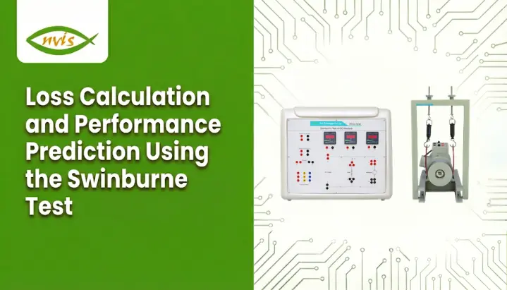
The Swinburne Test setup is an essential training system widely used in electrical laboratories for practical learning. It is particularly intended to make students and specialists aware of the fundamental principles, working nature, and performance appraisal of DC motors. The Swinburne Test provides the opportunity to determine losses separately and accurately predict the efficiency of the machine at any given load condition without physically loading it.
The armature and field winding terminals are separately brought out to an easily accessible terminal box located on top of the motor. The training system also offers special terminals to connect an external rheostat and starter to the control panel. This systematic design ensures clear observation, safe operation, and a comprehensive understanding of the experiment.
Related Blogs
- How a Digital LCR Meter Works: Step-by-Step Measurement Process
- How Electricity Training Lab Can Become a Part of School-Level Skill Education
- Preparing Future Technicians and Engineers for Smart Energy Management
What is the Swinburne Test?
The Swinburne Test is an indirect method developed by Sir James Swinburne to evaluate the performance and efficiency of DC shunt and compound machines. Since no mechanical load is applied during the test, it is also known as a no-load test.
This test is especially useful for large DC machines that cannot be tested under full-load conditions due to power limitations and mechanical constraints. It provides a simple, economical, and convenient way to predict the performance characteristics of a DC machine.
Principle of the Swinburne Test
In this test, the DC machine is operated as a motor at its rated voltage and rated speed. The speed is adjusted using a shunt field rheostat to maintain standard operating conditions.
The main objective of the Swinburne Test is to determine the constant losses of the machine, which include:
- Iron (core) losses
- Mechanical losses (friction and windage)
These losses are calculated from the no-load input power. Once the constant losses are known, the efficiency of the machine can be estimated at any desired load without actually loading the machine.
Technical Specifications Of Swinburne Test for DC Machine
DC Machine Specifications
- Type: DC Shunt Motor
- Power Rating: 1 HP (Optional variants available in 2 HP and 3 HP)
- Rated Voltage: 220 V ±10%
- Rated Speed: 1500 RPM ±5%
- Insulation Class: Class “B”
- Loading Arrangement: Mechanical loading system
- Brake Drum/Pulley: Cast aluminum construction
Digital Instrumentation
- DC Voltmeter: 0–300 V range
- DC Ammeter: 0–5 A (Two units provided)
- Digital Tachometer: Up to 20,000 RPM
Optional Accessories
- DC Power Supply (Model Nvis 725 / Nvis 725A)
- Suitable for machines rated up to 2 HP and 3 HP respectively
Loss Calculation and Performance Prediction
The main goal of the Swinburne Test is loss calculation and performance forecasting. This method enables engineers to determine the internal losses of a DC machine at no-load and estimate its efficiency at any desired load without physically loading it.
Loss Calculation
During the Swinburne Test of dc machine, the machine is operated at rated voltage and speed without load. The input power measured under this condition is mainly used to overcome constant losses. These losses include:
- Iron losses
- Mechanical losses
- Field copper loss
The armature copper loss at no load is calculated using the measured no-load voltage, line current, and field current. The constant losses are obtained by the difference between the total no-load input power and the armature copper loss.
The load current is used to calculate the variable loss, which is primarily the armature copper loss at the given load. Constant losses plus armature copper loss are then added to give total losses at the same load.
Performance Prediction
Once the losses are known, the efficiency of the machine can be predicted for different load conditions. For a motor:
- Input Power = V × I_L
- Total Losses = Constant Losses + Armature Copper Loss
- Output Power = Input Power − Total Losses
- Efficiency = (Output Power / Input Power) × 100
This method allows the engineers to draw efficiency against load and determine the condition of maximum efficiency. The Swinburne Test is therefore an effective and economical method for assessing the performance characteristics of DC shunt and compound machines without actual loading.
Scope of Learning
The learning span will entail studying and analyzing the various forms of losses that take place in a DC machine and how such losses influence the overall performance. By examining the Swinburne Test, the learners identify the constant and variable losses separately and apply the resulting information to compute and estimate the efficiency of the DC machine at different load conditions without actual loading. This strategy assists in coming up with a clear picture of performance assessment, loss computation techniques, and efficiency estimation techniques in DC machines.
Advantages and Disadvantages of Swinburne Test
Advantages
- Appropriate when large DC machines are to be tested, and no actual load is to be applied.
- Operates under no-load conditions, making it suitable for laboratory use.
- The level of input power required is very minimal as it only requires power to cover internal losses.
- Easy setup and less time consuming than direct load tests.
- Enables efficiency to be estimated at any desired load without physically loading the machine.
- Little wastage of energy in testing leading to low heat.
- Applicable to DC shunt and constant flux compound wound machines.
Disadvantages
- Iron losses are assumed constant, although they may vary between no-load and full-load conditions due to armature reaction.
- Fails to test commutation under real load conditions.
- Full-load temperature rise cannot be accurately determined using this test.
- Stray load losses are not considered, which can lead to inaccuracies in efficiency estimation.
- Not suitable for DC series motors, as no-load operation may be hazardous due to dangerously high speeds.
Conclusion
The Swinburne Test continues to be one of the most practical and cost-effective methods for determining efficiency and estimating losses in DC shunt machines. This is because, by measuring no-load input power and distinguishing between constant and variable losses, engineers can predict performance at various load conditions without physically loading the machine. This makes it especially valuable for large DC machines where direct loading would be impractical or economically inefficient.
To electrical engineers and learners, mastering this test gives a good understanding in machine testing, loss analysis and performance prediction.
FAQs
The Swinburne Test is an indirect, no-load test used to determine the efficiency and losses of DC shunt and compound machines without applying mechanical load. It calculates constant losses from no-load input power and predicts performance at different load conditions.
It is called a no-load test because the DC machine operates without any mechanical load during the experiment. The machine runs at rated voltage and speed, and only the internal losses are measured.
The test primarily determines:
- Iron losses
- Mechanical losses
- Field copper loss
Armature copper loss is then calculated separately to estimate total losses at different load conditions.
No. The Swinburne Test is suitable mainly for DC shunt and compound machines with relatively constant flux. It is not suitable for DC series motors because operating a series motor at no-load can result in dangerously high speeds.
The key advantages include:
- Low power consumption
- Simple and economical setup
- Suitable for large machines
- Ability to predict efficiency at any load without physical loading