TL;DR
- This blog is designed for electrical engineering students, lab instructors, industrial engineers, power plant professionals, and technical trainers seeking in-depth knowledge of synchronous generator and three phase synchronous generator performance.
- It explains the construction, operating principle, and synchronous speed concept of a three phase synchronous generator, including stator, rotor, excitation system, and prime mover.
- The blog details Open Circuit Characteristics (OCC), Short Circuit Characteristics (SCC), and external load characteristics under resistive, inductive, and capacitive loads.
- It breaks down power flow, types of losses, mechanical/electrical/commercial efficiency, and explains why maximum efficiency occurs when copper loss equals constant loss (typically at 75–85% load).
- It covers performance testing methods, compares synchronous generators with induction generators, and highlights real-world applications in thermal, hydro, nuclear, and industrial power systems.
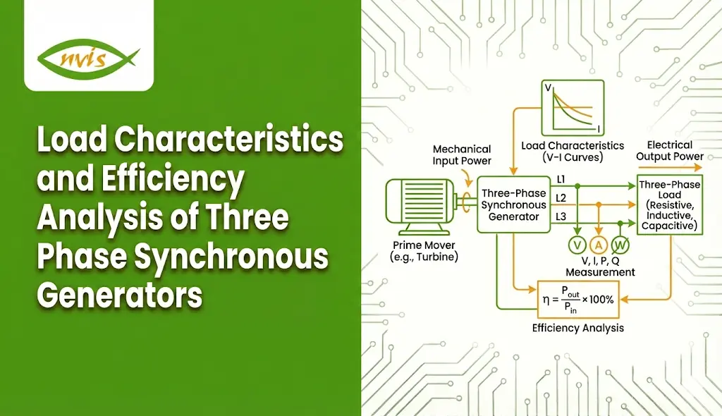
The Three Phase Synchronous Generator Lab is a specialized training system developed to provide in-depth understanding of the fundamental concepts and operating principles of a three phase synchronous generator. Since synchronous generators are the primary source of large-scale electrical power generation, they play a critical role in converting mechanical energy derived from steam, gas, or hydraulic turbines into AC electrical power.
This laboratory setup enables hands-on experimentation, allowing users to study important characteristics such as the Open Circuit Characteristic (OCC) and analyze the relationship between field current and armature voltage. The system is designed for ease of operation, making it suitable for educational institutions and technical training environments.
For enhanced safety and reliability, all necessary protection circuits are built into the system, significantly minimizing the risk of faults or hazards to users. Its comprehensive experimental capabilities ensure a thorough and practical understanding of synchronous generator performance and behavior.
Related Blogs
- How Electricity Training Lab Can Become a Part of School-Level Skill Education
- Preparing Future Technicians and Engineers for Smart Energy Management
- What Is a Data Acquisition System and How Does It Work?
Fundamentals of a Synchronous Generator
What is a Synchronous Generator?
A synchronous generator is an AC machine that converts mechanical power into electrical power while operating at a speed synchronized with the frequency of the electrical grid. The rotor rotates at synchronous speed, which is directly related to the supply frequency and number of poles.
The synchronous speed is given by:
Ns = (120 × f) / P
Where:
- Ns = Synchronous speed (rpm)
- f = Frequency (Hz)
- P = Number of poles
For example:
- A 4-pole generator at 50 Hz runs at 1500 rpm
- A 2-pole generator at 60 Hz runs at 3600 rpm
A key feature of a synchronous generator is that rotor speed remains constant under steady-state conditions, regardless of load (assuming constant mechanical input and grid connection).
Construction of a Three Phase Synchronous Generator
A three phase synchronous generator is constructed using carefully designed components that work together to convert mechanical energy into electrical energy efficiently. The machine consists of four major parts: the stator, rotor, excitation system, and prime mover. Each component plays a vital role in ensuring stable voltage generation and reliable operation under varying load conditions.
1. Stator (Armature)
The stator is the stationary part of the generator and houses the armature winding where electrical power is produced. It is built using a laminated silicon steel core to minimize eddy current losses and improve efficiency. Three-phase distributed windings are placed in slots along the inner periphery of the stator core. When the magnetic field produced by the rotor rotates, it cuts the stator conductors and induces a three-phase alternating voltage. The stator structure is designed for mechanical strength, proper insulation, and efficient heat dissipation.
2. Rotor (Field System)
The rotor is the rotating component of the synchronous generator and carries the field winding. It is excited with DC supply to create the magnetic field required for electromagnetic induction. The rotor rotates at synchronous speed, determined by the system frequency and number of poles. There are two main types of rotors used in a three phase synchronous generator. The salient pole rotor is used for low-speed applications such as hydroelectric plants and has a large diameter with projecting poles. The cylindrical or non-salient pole rotor is used for high-speed turbo alternators and has a smooth cylindrical construction for better mechanical balance at high speeds.
3. Excitation System
The excitation system supplies DC power to the rotor winding and controls the generator’s terminal voltage. By adjusting the field current, the output voltage and reactive power can be regulated. Modern generators use either brushless excitation systems or static excitation systems to ensure reliable and maintenance-friendly operation. Proper excitation is essential for voltage regulation and system stability.
4. Prime Mover
The prime mover provides the mechanical energy required to rotate the rotor. Depending on the application, different types of prime movers are used. Steam turbines are commonly used in thermal power plants, water turbines in hydroelectric plants, gas turbines in combined cycle plants, and diesel engines in smaller or standby power systems. The prime mover must maintain synchronous speed to ensure constant frequency output from the generator.
Operating Principle of a Three Phase Synchronous Generator
The working principle of a three phase synchronous generator is based on Faraday’s Law of Electromagnetic Induction. When the rotor, excited by DC current, rotates at synchronous speed, it produces a rotating magnetic field. This magnetic field cuts the stationary stator conductors and induces an EMF in the stator windings.
Since the stator has three windings placed 120° apart, the induced voltages are also 120° out of phase, resulting in a balanced three-phase AC output.
Load Characteristics of a Synchronous Generator
The load characteristics of a synchronous generator describe how its terminal voltage and output current vary when different types of loads are connected. In a three phase synchronous generator, these characteristics are crucial for understanding voltage regulation, stability, and overall performance under practical operating conditions. Engineers rely on these characteristic curves to predict generator behavior accurately under varying load conditions.
No-Load (Open Circuit) Characteristics – OCC
The Open Circuit Characteristic (OCC) represents the relationship between generated EMF (E₀) and field current (I_f) when the synchronous generator operates at rated speed without any load connected. Initially, the curve is linear because the magnetic circuit is unsaturated. As the field current increases further, magnetic saturation occurs, and the curve gradually flattens. The OCC represents the magnetization characteristic of the synchronous generator and is essential for determining rated excitation and saturation limits and is essential for determining the rated field current and studying saturation behavior in a three phase synchronous generator.
Short Circuit Characteristics – SCC
The Short Circuit Characteristic (SCC) shows the relationship between armature current (I_a) and field current (I_f) when the armature terminals of the synchronous generator are short-circuited. Under this condition, the magnetic circuit remains unsaturated, resulting in a linear relationship between field current and armature current. The SCC is primarily used to determine synchronous impedance, which is essential for voltage regulation and short-circuit fault analysis in a three phase synchronous generator.
External Load Characteristics
The external characteristic of a synchronous generator represents the variation of terminal voltage (V) with load current (I_L) at constant speed and constant excitation. This behavior changes depending on the type of load connected to the three phase synchronous generator.
Under a resistive load (unity power factor), the terminal voltage drops slightly as the load increases due to armature resistance and reactance. Voltage regulation remains relatively small in this case.
When supplying an inductive load (lagging power factor), the terminal voltage decreases significantly with increasing load. This is because armature reaction becomes demagnetizing, resulting in higher voltage regulation. Such conditions are common in industrial motor loads.
For a capacitive load (leading power factor), the terminal voltage may increase as the load increases. Here, armature reaction becomes magnetizing, which strengthens the main magnetic field. This condition is often observed in systems using power factor correction equipment.
Efficiency Analysis of Synchronous Generator
Efficiency is a critical performance parameter of a synchronous generator, as it indicates how effectively mechanical input power is converted into useful electrical output power. In large power systems, even a small improvement in efficiency can result in significant energy savings.
Efficiency (η) of a synchronous generator is defined as:
η = (Output Power / Input Power) × 100
Where:
- Output Power = Electrical power delivered at the terminals
- Input Power = Mechanical power supplied by the prime mover
In a three phase synchronous generator, high efficiency is achieved through optimized design, high-quality magnetic materials, and advanced cooling systems.
Types of Efficiency
To better understand performance, efficiency in a synchronous generator is categorized into three types:
1. Mechanical Efficiency
Mechanical efficiency represents how effectively mechanical input power is converted into air-gap power (power transferred from rotor to stator).
Mechanical Efficiency = Air Gap Power / Mechanical Input
It accounts for mechanical losses such as friction and windage.
2. Electrical Efficiency
Electrical efficiency indicates how efficiently the air-gap power is converted into electrical output power at the stator terminals.
Electrical Efficiency = Output Power / Air Gap Power
It accounts for stator copper losses and core losses.
3. Commercial Efficiency
Commercial efficiency, also known as overall efficiency, represents the total efficiency of the three phase synchronous generator.
Commercial Efficiency = Output Power / Mechanical Input
This is the most commonly specified efficiency value in generator ratings.
Performance Testing Methods of a Synchronous Generator
Performance testing of a synchronous generator helps evaluate voltage regulation, impedance, and overall behavior under different operating conditions. In a three phase synchronous generator, the following standard tests are commonly performed:
1. Open Circuit Test (OCC)
Conducted at rated speed with no load connected. It determines the Open Circuit Characteristic (OCC) curve and helps study magnetic saturation and rated field current.
2. Short Circuit Test (SCC)
Performed by short-circuiting the armature terminals. It determines the Short Circuit Characteristic (SCC) curve and is used to calculate synchronous impedance.
3. Load Test
The generator is connected to an actual load to measure real performance, voltage regulation, and efficiency.
4. EMF Method
Uses OCC and SCC data to estimate voltage regulation without conducting a full-load test.
These tests are essential for analyzing voltage regulation, impedance, and real-world performance of a three phase synchronous generator.
Comparison with Other Generators
Feature | Synchronous Generator | Induction Generator |
Speed | Constant | Variable |
Excitation | Required | Not required |
Voltage control | Excellent | Limited |
Power factor control | Yes (via excitation control) | Limited (depends on system) |
The synchronous generator provides superior voltage and reactive power control.
Applications of Three Phase Synchronous Generator
- Thermal power plants
- Hydro power plants
- Nuclear plants
- Diesel power stations
- Wind farms (with synchronous machines)
- Industrial captive generation
Conclusion
The synchronous generator remains the most critical machine in modern power systems. A properly designed and maintained three phase synchronous generator provides stable voltage, high efficiency, and reliable power generation under varying load conditions.
Understanding load characteristics helps engineers predict voltage behavior under resistive, inductive, and capacitive loads. Efficiency analysis reveals how losses affect performance and how optimal loading improves energy conversion effectiveness.
From voltage regulation and armature reaction to power flow and maximum efficiency conditions, mastering these concepts enables better generator design, operation, and maintenance.
In large-scale power plants, efficiency values exceeding 98% demonstrate the advanced engineering and optimized design of synchronous generators. With continued advancements in materials, cooling systems, and excitation control, these machines will remain at the core of global energy infrastructure for decades to come.
FAQs
A synchronous generator is a machine that converts mechanical energy into electrical energy and runs at a constant speed synchronized with the supply frequency.
A three phase synchronous generator produces three-phase AC power and is widely used in power plants for large-scale electricity generation.
OCC (Open Circuit Characteristic) shows the relationship between field current and generated voltage without load.
SCC (Short Circuit Characteristic) shows the relationship between field current and armature current when the generator is short-circuited.
Voltage drops under load due to internal resistance, reactance, and armature reaction, especially with inductive (lagging power factor) loads.
Efficiency is calculated as:
Efficiency = (Output Power / Input Power) × 100
It shows how effectively input mechanical power is converted into electrical power.