• Nvis Technology
  • Nvis Technology
  • Nvis Technology
  • Nvis Technology
  • Nvis Technology
  • Nvis Technology
Nvis Technology

Head Office

141-A, Electronic complex, Pardesipura,Indore - 452010 India

Phone: +91 73899 00887 , +91 98932 70303

Email:info@nvistech.com

Request a Quote

Looking for a quality and affordable builder for your next project?


    Nvis Technology

    Toll Free

    +91 73899 00887

    We are happy to meet you during our working hours. Please make an appointment.

    • Monday-Saturday: 9:00 AM - 5:30 PM (IST)
    • Sunday: Closed

    Why Electric Vehicle Labs are Essential for Modern Engineering Education

    TL;DR

    • This blog is designed for engineering students, electrical and mechanical engineering faculty, academic institutions, and professionals interested in electric vehicles and sustainable transportation technologies.
    • The rapid growth of electric vehicles is transforming the automotive and energy sectors worldwide.
    • Engineering education must evolve to prepare students with practical knowledge of EV systems and electric vehicle charging station infrastructure.
    • Electric Vehicle (EV) labs provide hands-on training in battery systems, motor control, power electronics, and charging technologies.
    • By integrating EV laboratories into engineering programs, institutions can produce industry-ready graduates capable of contributing to the global EV transition.
    Why Electric Vehicle Labs are Essential

    The transportation sector is undergoing a major technological transformation. Governments, industries, and researchers around the world are striving to minimize carbon emissions and reduce reliance on fossil fuels. Electric cars are one of the best solutions that can be adopted to ensure this is achieved.

    EV technology has rapidly evolved from a niche concept to a mainstream transportation solution. Large automobile companies are spending billions of dollars in the development of electric vehicles. Governments are providing incentives to accelerate EV adoption, and cities are developing infrastructure, including networks of electric vehicle charging stations, to serve the increasing population of EV users.

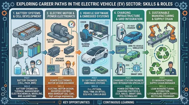
    Due to the growing electric vehicle ecosystem, the demand for engineers with expertise in EV technology is growing exponentially. Electric vehicles include complex systems such as battery management, power electronics, electric motors, control systems, and intelligent charging infrastructure. These technologies require specialized knowledge which is not limited to traditional automotive engineering.

    Related Blogs


    Understanding Electric Vehicle Labs

    Electric Vehicle Labs are specialized training laboratories, designed to help students analyze and experiment with electric mobility-related technologies. These laboratories combine theoretical knowledge with practical experience and students are able to work directly with actual EV components and systems.

    EV laboratories also specialize in electrical propulsion systems, energy storage technologies, and charging infrastructure unlike traditional automotive labs, which primarily focus on internal combustion engines.

    An EV laboratory with the right equipment usually has a number of training modules and even experimental equipment that can be used to showcase the fundamental technologies involved in the electric vehicles.

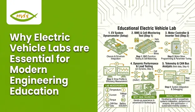
    Key Components of an Electric Vehicle Lab

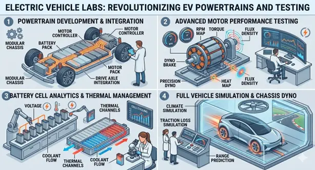
    Electric Motor Training Systems

    Electric vehicles depend on electric motors. EV laboratories offer facilities to enable students to learn about the various types of motors including brushless DC motors, permanent magnet synchronous motors, and induction motors. Students get to know about motor control methods, torque-speed profile and efficiency optimization.

    Battery Management Systems

    Electric vehicles rely mostly on batteries as their power source. EV laboratories have battery modules and Battery Management System (BMS) training packages that aid the students to learn about battery monitoring, battery safety, charge balancing and thermal management.

    Power Electronics Modules

    Power electronics are important in the functioning of EV. Inverters, converters and motor controllers control the flow of energy between the battery and the motor. Students can study the application of power electronics in enhancing performance and efficiency of the vehicle using laboratory experiments.

    Electric Vehicle Charging Station Trainers

    The electric vehicle charging station is one of the most significant components of the EV infrastructure. EV labs may also have EV charging station training modules, which may show how EVs are charged, the various charging standards, and how EV charging stations interface with vehicles and the power grid.

    EV System Integration Platforms

    High-tech EV laboratories can also have entire electric vehicle training areas in which students can study how the motor and battery interface with the controller and charging system.

    These integrated systems help students understand the entire EV ecosystem.

    Why Electric Vehicles Are Transforming Engineering Education

    The swift increase in the use of electric vehicles is transforming the skills of engineers. Conventional automotive engineering courses paid a lot of attention to internal combustion engines, mechanical systems, and fuel-powered engines.

    However, electric vehicles require knowledge about electrical engineering, electronics, energy storage and digital control systems.

    Engineering education must evolve to keep pace with these changes.

    Rapid Industry Growth

    The market of EVs grows at an unprecedented speed worldwide. Electric mobility and emission policies are being adopted by countries globally. The automobile companies are shifting towards electric systems and leaving the fuel-powered vehicles.

    Therefore, industries are in the search of engineers who have the knowledge of electric vehicles and electric vehicle charging station technologies.

    New Career Opportunities

    The booming EV business is offering numerous professional jobs to the graduates of engineering. Firms are seeking experts knowledgeable in the electric cars and infrastructure, such as the electric vehicle charging station network.

    Electric vehicle manufacturing, battery technology, development of charging infrastructure, renewable energy integration, and smart grid technologies are some of the industries comprising the EV ecosystem. Since the switch towards electric cars is growing, engineers with expertise in EV systems and charging infrastructure are currently in high demand.

    Electric Vehicle

    Interdisciplinary Learning

    Engineering of electric cars combines several spheres of engineering. These are electrical engineering, mechanical engineering, electronics and control systems, energy systems engineering, and computer science with embedded systems.

    EV labs provide students with real-world exposure to how these disciplines integrate in practice, helping them understand the complete EV ecosystem.

    The Importance of Hands-On Learning in EV Education

    As much as theoretical education is a requirement, engineering education becomes effective when students are able to apply concepts in practice in the real world.

    Electric vehicle technology is complex and comprises a number of interacting systems. Reading these technologies in textbooks or lectures cannot make one get a complete grasp on the practical uses of these technologies.

    Practical Understanding of EV Systems

    Students who are in EV labs are able to see the interaction between the various components. They are able to measure motor efficiency, investigate battery performance as well as understand how power electronics manage energy flow in the vehicle.

    Learning Charging Infrastructure

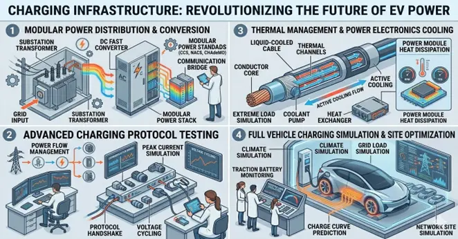
    The knowledge of the functioning of an electric vehicle charging station is essential to the engineers involved in the EV ecosystem. Charging stations encompass the communication protocols, power management systems, safety standards, and grid connection.

    The laboratory experiments will enable students to model the real-world charging situations and examine the way in which the charging infrastructure behaves with vehicles and power networks.

    Problem-Solving Skills

    Practical training helps the students to troubleshoot and create novel solutions. This skill would be necessary among engineers that will plan and support EV technologies in the field.

    Electric Vehicle Charging Station Technology

    One of the most significant aspects of electric mobility development is the increase in the number of electric vehicle charging stations.

    The large-scale use of electric vehicles cannot be achieved without the availability and a stable system of charging networks.

    EV laboratories enable the learners to learn the specifics of charging technologies.

    Types of Charging Stations

    Level 1 Charging

    Level 1 charging utilizes normal household electric sockets and offers slow charging rates. Although convenient, it is mostly applied in residential charging.

    Level 2 Charging

    Level 2 charging stations have high voltages and charge faster. Such stations are usually located at home, workplace and in the parking lots.

    DC Fast Charging

    DC fast chargers offer high power DC electricity which is supplied directly to the vehicle battery and is therefore a rapid way of charging the battery. These charging devices are commonly placed at highways and business premises.

    Students who are in the EV laboratories are able to study the effectiveness and performance of these charging systems.

    Benefits of Electric Vehicle Labs for Engineering Students

    Electric Vehicle Labs have a lot of benefits to a student in the engineering learning process.

    Industry-Relevant Skills

    Students obtain the practical understanding of the EV systems, battery management, motor control, and the charging infrastructure. Employers in the EV industry enjoy these skills.

    Improved Career Opportunities

    Individuals who have acquired knowledge in electric vehicles and electric vehicle charging station technologies can work in the automotive engineering, energy systems, and smart mobility sectors.

    Research Opportunities

    EV laboratories help in research and innovation when it comes to battery technology, charging efficiency and sustainable transportation solutions.

    Innovation and Entrepreneurship

    The learners who are involved in EV technologies can come up with new solutions, prototypes, and startup ideas concerning electric mobility.

    Benefits of Electric Vehicle Labs for Universities

    Another important advantage of building EV laboratories is the engineering institutions.

    Modernizing Academic Programs

    Establishing EV labs is one way of ensuring that the universities modernize their engineering programs, in order to align with emerging industry technologies.

    Industry Collaboration

    Most firms in the EV industry partner with universities in research and talent development.

    Those institutions that have EV labs will be more able to attract the partnership and funding of industry leaders.

    Supporting Sustainability Goals

    Environmental sustainability is highly associated with electric mobility. Universities can also help to decrease the emission of greenhouse gases in the world by facilitating the teaching of EV.

    Conclusion

    Electric mobility is transforming the transportation industry across the world. Electric cars have ceased to be the dream of tomorrow, they are quickly becoming the mode of transport in most regions across the globe.

    Electric Vehicle Labs give the students hands-on experience of EV technology, such as motor, battery management, power, and electric vehicle charging station infrastructure. These laboratories span the divide between theory and practice in engineering.

    Universities can equip students with skills in electric mobility by offering EV laboratories as part of their degrees to help them get ready to work in the fast-developing electric mobility industry. Meanwhile, these labs facilitate research, innovation, and academia-industry collaboration.

    With the development of the EV ecosystem, professionals with electric vehicle technologies experience will be instrumental in creating a better, more sustainable future of transportation.

    Electric Vehicle Labs are not only an educational tool but also a platform for developing the next generation of engineers who will lead the transition toward electric mobility.

    FAQs

    An Electric Vehicle (EV) lab is a dedicated training center, in which the students gain knowledge of electric vehicles, battery setup, motor control, power electronics, and electric vehicle charging station technologies via active experimentation.

    EV labs offer a practical experience that assists students in learning about EV systems, charging infrastructure, and energy management to prepare them to work in the emerging electric vehicles field.

    Students are taught about electric motors, battery management systems, power electronics, EV powertrains, and electric vehicle charging station infrastructure which is used to charge and control electric vehicles.

    EV labs contribute in making the skilled engineers that have the ability to design, maintain and create technologies that are connected with electric vehicles and electric vehicle charging stations networks.

     EV trained students are employed in the production of electric vehicles, battery technology, charge infrastructure development, renewable energy integration and smart grids.

    Tags: electric vehicle charging station, electric vehicles

    Load Flow and Voltage Regulation in Radial and Ring Distribution Systems

    TL;DR –

    1. This blog is designed for electrical engineering students, power system engineers, trainers, technical institutions, and industry professionals who want to understand load flow and voltage regulation in a ring and radial distribution system.
    2. Load flow (power flow analysis) determines voltage magnitude, phase angle, active and reactive power flow, and line losses in radial and ring main distribution systems, forming the foundation for efficient network planning and operation.
    3. A well-designed ring distribution system or radial system must maintain voltage variation within ±5% to ensure stable and reliable power supply to consumers.
    4. Radial systems are simple and economical but experience higher voltage drops and lower reliability, while ring systems provide bi-directional power flow, reduced losses, better voltage regulation, and improved reliability.
    5. The Nvis training system enables hands-on analysis and voltage regulation are transforming both radial and ring distribution systems.

    The distribution of electric power is the final and most important stage in delivering electricity from generating stations to consumers. While transmission networks carry bulk power over long distances, distribution systems deliver safe, reliable, and quality power to homes, industries, and commercial facilities. The most popular configurations include the ring and radial distribution system, which have several distinct operational features, reliability, and voltage performance.

    Electrical engineers, planners, and energy managers should understand load flow and voltage regulation in radial and ring main distribution systems. Effective load flow analysis is essential for proper network operation, and voltage regulation ensures a stable power supply within acceptable limits.

    This guide explains the structure, analysis methods, voltage behavior, mathematical modeling, comparison, and modern developments in radial and ring distribution systems.


    Related Blogs

    1. How to Use a Programmable DC Power Supply Safely in Student Laboratories
    2. Preparing Future Technicians and Engineers for Smart Energy Management
    3. What Is a Data Acquisition System and How Does It Work?

    Load Flow and Voltage Regulation

    Two basic performance parameters in any electrical distribution network include load flow and voltage regulation. These parameters are analyzed in ring and radial distribution systems to ensure efficient power delivery, stable voltage levels, and minimal losses. A radial and a ring main distribution system require proper analysis of load flow and voltage regulation in order to ensure quality and reliable provision of power.

    What is Load Flow?

    Load flow (or power flow) analysis is the systematic study of how electrical power moves through a distribution network. It determines:

    • Voltage magnitude at each bus
    • Phase angle at each node
    • Active power (kW) flow
    • Reactive power (kVAR) flow
    • Line losses

    In a ring distribution system, power may flow in multiple directions due to the closed-loop configuration. In contrast, in a radial system, power flows in only one direction from the source to the load.

    What is Voltage Regulation?

    Voltage regulation measures the change in voltage at the consumer terminal between no-load and full-load conditions.

    Voltage Regulation = (V_no-load − V_full-load) / V_full-load × 100%

    A well-designed ring and radial distribution system should maintain voltage variation within ±5% of the rated value.

    Radial and Ring Main Distribution System

    The Radial and Ring Main Distribution System training setup is designed to demonstrate the operating principles of both radial and ring main electrical distribution networks. A distribution system is an essential component of the electric power system, which connects high-voltage transmission networks to low-voltage service points of consumers. These systems should be designed so that voltage variation at consumer terminals does not exceed ±5% of the rated value.

    The Nvis training system provides in-depth practical learning support for manually developing and analytically assessing both ring and radial distribution system designs. Structured experiments and comparative studies help learners clearly understand the performance differences between the two systems.

    The system consists of a built-in DC variable power supply, including sufficient safety controls and digital metrology. The radial and ring main structures are covered in separate sections where students can study each system step-by-step and understand their operational significance.

    Product Features

    • Three digital DC voltmeters and three digital DC ammeters for precise measurement
    • Dedicated connection panels for both radial and ring main systems
    • Built-in DC variable power supply
    • Isolation transformer for enhanced operational safety
    • Exclusive and ergonomically designed control panel
    • Integrated lamp load holders
    • Clear diagrammatic representation for easy circuit connections

    Comparative View: Load Flow and Voltage Regulation

    Parameter

    Radial System

    Ring Distribution System

    Power Flow

    Single direction

    Bi-directional

    Voltage Drop

    Higher

    Lower

    Losses

    Higher

    Reduced

    Reliability

    Lower

    Higher

    Complexity

    Simple

    Moderate

    Load Flow in Distribution Systems

    Load flow, or power flow analysis, evaluates the operating condition of a distribution network. In a ring and radial distribution system, it determines:

    • Voltage magnitude at each bus
    • Phase angle at each bus
    • Active power (P) and reactive power (Q) flow
    • Line losses

    In a radial and ring main distribution system, load flow analysis ensures proper voltage levels, efficient power delivery, and reliable operation. It forms the foundation of effective planning, design, and performance optimization in any ring distribution system.

    Load Flow in Ring Distribution System

    Power Flow Characteristics

    A ring distribution system involves a closed-loop feeder configuration where power flows in both directions toward the load. Unlike the single power path in a radial setup, load current in a ring network is shared between two paths. With current shared between two paths, the current in each section is reduced, resulting in a more uniform voltage drop and lower overall line losses. The multi-path design of a ring distribution system enhances voltage stability and provides a more uniform voltage profile across all load points.

    Mathematical Considerations

    In a ring distribution system, electrical loops are closed. This means that Kirchhoff Voltage Law (KVL) needs to be met around every loop and loop current analysis is necessary. Ring systems require more complex iterative techniques for analysis, whereas radial systems can often be solved using simpler methods to determine voltage magnitude, phase angle, and power flow. The typical methods are the Newton-Raphson method, Gauss-Seidel method, and modified Forward-Backward Sweep method. These methods help in accurate analysis of load flow within a ring distribution system.

    Voltage Regulation in Ring System

    Since the current in a ring-type of distribution flows in two directions, the line current in each piece of the feeder is less. This results in reduced I²R losses and lower voltage drop across the network. Consequently, voltage regulation is better than in radial systems. The improved voltage profile and reliability of ring systems make them well suited for urban and industrial distribution networks where voltage stability is critical.

    Conclusion

    Performance parameters in any distribution network are load flow and voltage regulation which are paramount. Ring and radial distribution systems represent two different design philosophies with distinct operational characteristics.

    Radial systems are cheap, easy, and may be applied in sparsely populated regions but have greater voltage drops and reduced reliability.

    In contrast, the ring distribution system offers:

    • Improved voltage regulation
    • Reduced losses
    • Better reliability
    • Enhanced operational flexibility

    The choice between radial and ring main distribution systems depends on cost, load density, reliability requirements, and operational complexity.

    With the advent of smart grids and renewable integration, distribution systems are becoming intelligent, adaptive networks capable of maintaining excellent voltage profiles and efficient load flow performance.

    FAQs

    A ring and radial distribution system refers to two types of power distribution networks. A radial system has a single path from source to load, while a ring system forms a loop that allows power to flow in two directions.

    Load flow analysis helps calculate voltage levels, power flow, and line losses in a radial and ring main distribution system, ensuring safe and efficient operation.

    Voltage regulation is the change in voltage between no-load and full-load conditions. A good ring distribution system maintains voltage within ±5% of the rated value.

    A ring distribution system is more reliable because power can reach the load from two directions, reducing the chance of complete supply failure.

    Radial systems are commonly used in rural or low-load areas because they are simple, economical, and easy to maintain.

    Tags: radial and ring main distribution system, ring and radial distribution system, ring distribution system

    Relay Coordination Techniques for Over Current and Earth Fault Protection

    TL;DR –

    • This blog is designed for electrical engineers, protection engineers, power system professionals, engineering students, and technical trainers who want to understand current and earth fault relay systems and techniques of coordination in depth.
    • An overcurrent and earth fault relay protects electrical systems from overloads, short circuits, and ground faults by detecting abnormal current conditions and tripping breakers before damage occurs.
    • Proper techniques of coordination ensure selective tripping, only the relay nearest to the fault operates, preventing unnecessary outages and maintaining system stability.
    • Effective relay coordination involves data collection, fault current calculation, curve selection, pickup and time settings adjustment, TCC curve plotting, and thorough testing.
    • Earth Fault Relay Testing Systems provide hands-on training to study relay characteristics, connections, and performance verification, helping students and professionals build practical protection expertise.

    Modern power systems are designed to deliver electricity safely, reliably, and efficiently. However, electrical circuits are constantly exposed to disturbances such as short circuits, overloads, insulation failures, and ground faults. These faults, if not properly protected against, may cause equipment damage, fire hazards, and widespread outages.

    At the core of electrical protection systems is the over current and earth fault relay, a fundamental device that monitors abnormal current conditions and isolates faulty sections before damage escalates.

    Related Blogs –

    Over Current and Earth Fault Protection

    Electrical systems operate within specified current limits. Protection devices must respond promptly whenever current exceeds normal limits due to faults or abnormal conditions.

    Two of the most common fault types in power systems are:

    • Over current faults – caused by overloads or short circuits
    • Earth faults (ground faults) – caused when a conductor comes into contact with ground or grounded structures

    The over current and earth fault relay offers protection in both scenarios. It measures current on a line using current transformers (CTs) and triggers breaker tripping upon meeting preset thresholds.

    In multi-level distribution systems, relays are installed at feeders, transformers, busbars, and main incomers. If all relays trip simultaneously during a fault, the entire system may shut down unnecessarily.

    This is where techniques of coordination become critical.

    Earth Fault Relay Testing System

    The Earth Fault Relay Testing System provides hands-on exposure to protection devices used to prevent faults caused by earth leakage currents. Effective protection is essential to ensure the safety and reliability of electrical systems.

    Power systems make use of a number of protective devices, and studying how they work helps to use them in smarter ways and avoid system failures. Earth leakage current may cause excess heat and insulation degradation over time, and finally cause earth faults and sparking. An Earth Fault Relay senses leakage currents before they reach the preset threshold, thus safeguarding equipment and ensuring operational safety.

    Nvis provides an interactive learning environment that demonstrates the connection of an Earth Fault Relay in a transmission line and allows testing of its operation. Through practical demonstrations using Nvis systems, students gain hands-on experience in the application and testing of Earth Fault Relays in power systems.

    The Earth Fault Relay Testing System is an ideal educational platform for improving technical knowledge, practical training, and skill development among students and young professionals.

    Product Features

    • Inbuilt variable source
    • Large-font LCD display for clear visibility
    • Isolation transformer for safe operation
    • Durable and rugged panel design
    • Engineered with comprehensive safety considerations
    • Diagrammatic representation for easy connections

    Scope of Learning

    • Study and verification of Earth Fault Relay operating characteristics under different plug settings
    • Understanding the connection of an Earth Fault Relay in a transmission line
    • Practical testing procedures of an Earth Fault Relay

    Fundamentals of Over Current and Earth Fault Relays

    Overcurrent protection operates when current exceeds a predefined pickup value. Overcurrent may result from:

    • Overloads
    • Phase-to-phase short circuits
    • Three-phase faults

    Overcurrent relays are classified into:

    1. Instantaneous Relays – operate with no intentional delay
    2. Definite Time Relays – operate after a fixed delay
    3. Inverse Time Relays – operating time decreases as fault current increases

    Inverse time characteristics are widely used because they provide better discrimination.

     What Are Earth Fault Relays?

    Earth faults occur when current flows from phase conductors to ground due to insulation failure, cable damage, or equipment breakdown.

    Earth fault protection is essential because:

    • Ground faults may produce lower fault currents than phase faults
    • They can cause severe damage if undetected
    • Personnel safety is at risk

    Earth fault relays are typically more sensitive and operate at lower pickup settings than phase overcurrent relays.

    Combined Over Current and Earth Fault Relay

    A modern over current and earth fault relay integrates both protection functions into a single numerical device. Benefits include:

    • Reduced panel space
    • Improved accuracy
    • Multiple characteristic curve options
    • Communication capability
    • Event recording and fault analysis

    Importance of Relay Coordination

    Relay coordination ensures that only the protection device closest to the fault operates, while upstream devices remain active unless backup protection is required. When an over current and earth fault relay is properly coordinated, unnecessary power interruptions are avoided, and system stability is maintained.

    Objectives of Coordination

    • Selectivity – Isolate only the faulty section
    • Reliability – Operate correctly during faults
    • Speed – Clear faults quickly
    • Sensitivity – Detect low-level fault currents
    • Backup Protection – Provide redundancy if primary protection fails

    Step-by-Step Relay Coordination

    Systematic relay coordination study is critical in order to make sure that the over current and earth fault relay can work with an acceptable level of selectivity, reliability, and speed. Effective techniques of coordination follow a systematic engineering approach, as described below.

    Step 1: Data Collection

    The first step is collecting accurate system data. It comprises the single-line diagram (SLD), transformer ratings and impedance, cable sizes and lengths, CT ratios with accuracy class, and short-circuit levels available at different buses. Accurate data ensures reliable setting calculations and proper coordination.

    Step 2: Fault Current Calculation

    Then determine the anticipated fault currents in various system points. These are normally the three-phase faults, the line-to-line faults and the earth faults. Fault current values are used to set relay pickup settings and also assist in setting the time delays required in selective operation.

    Step 3: Select Relay Characteristics

    Select appropriate inverse time characteristics depending on the behavior and protection needs of a system. The most common are standard inverse, very inverse and extremely inverse curves. Selecting the correct curve is a critical aspect of relay coordination.

    Step 4: Set Pickup Current

    Relay pickup current is usually adjusted to between 125 and 150 percent of full load current. This prevents unnecessary tripping under normal conditions while ensuring reliable operation during fault conditions.

    Step 5: Set Time Multiplier

    Adjust the time multiplier (time dial setting) to maintain adequate coordination margin between downstream and upstream relays. This guarantees that the nearest relay will clear the fault first with the upstream devices acting as a backup.

    Step 6: Plot TCC Curves

    Time-Current Characteristic (TCC) curves are plotted using professional coordination software such as ETAP, DIgSILENT, or SKM. These plots help visually verify proper separation and coordination between relay curves.

    Step 7: Verify and Test

    Finally, verify the settings through secondary injection testing and commissioning validation. During testing, it is important to make sure that the over current and earth fault relay functions precisely as desired when the fault conditions are simulated.

    Conclusion

    Electrical protection is not merely about installing relays; it is about coordinating them to operate selectively and precisely. With a correctly implemented protection scheme, only the faulty part of the system is disconnected and the rest of the system keeps on functioning. Such performance is achieved only through systematic application of proven coordination techniques.

    When properly coordinated, engineers achieve selective fault isolation, shield major equipment of thermal and mechanical harm, reduce expensive downtime, and enhance the general reliability of the system greatly. These advantages have vital roles in ensuring continuity of operation within industrial, commercial and utility power systems.

    The over current and earth fault relay remains one of the most essential components of modern electrical protection systems. It offers reliable fault detection, quick clearance, and efficient backup protection when programmed using a thorough and systematic coordination examination. Relay coordination is not a luxury in modern power networks—whether in a manufacturing facility or a smart grid, it is a necessity for ensuring a robust and future-proof electrical system.

    FAQs

    An over current and earth fault relay is a protection device used in power systems to detect excessive current and ground (earth) faults. It monitors current through current transformers (CTs) and trips the circuit breaker when preset limits are exceeded, protecting equipment from damage.

    Proper techniques of coordination ensure that only the relay closest to the fault operates first, while upstream relays act as backup. This prevents unnecessary outages and maintains system stability.

    The key objectives include selectivity, reliability, speed, sensitivity, and backup protection. These ensure faults are cleared quickly without affecting healthy parts of the electrical system.

    Overcurrent protection responds to excessive phase currents caused by overloads or short circuits, while earth fault protection detects leakage current flowing to ground due to insulation failure or conductor contact with earth.

    TCC curves show the relationship between fault current magnitude and relay operating time. They are used in coordination studies to ensure proper separation between upstream and downstream relay settings.

    Tags: over current and earth fault relay, techniques of coordination

    Hydrogen Education Labs: Preparing the Next Generation of Clean Energy Engineers

    TL;DR

    • This blog is designed for engineering students, energy researchers, educators, clean energy professionals, and industry engineers who want to understand how hydrogen education labs prepare future experts in green hydrogen and hydrogen renewable energy technologies.
    • Hydrogen is a powerful energy carrier that supports decarbonization, especially when produced as green hydrogen using renewable electricity.
    • Universities are establishing hydrogen labs to provide hands-on training with technologies such as hydrogen generator systems, electrolyzers, fuel cells, and hydrogen storage solutions.
    • Students gain practical experience with green hydrogen production, hydrogen generators, fuel cells, hydrogen storage methods, and renewable energy integration.
    • Hydrogen education labs bridge the gap between theory and industry needs, helping train engineers capable of designing and managing future hydrogen renewable energy

    The global energy landscape is changing rapidly. Governments, industries, and research organizations around the world are working to reduce reliance on fossil fuels while ensuring secure and scalable energy systems.Hydrogen is one of the most promising energy carriers among the various options being considered for a sustainable energy future.

    Hydrogen is a versatile, energy-dense carrier that can support multiple energy applications and can drive industries, transportation, and power production. When produced using renewable energy, it becomes green hydrogen and can result in near-zero carbon emissions during production. This renders hydrogen a crucial element in the international initiative in curbing climate change.

    However, the rapid growth of hydrogen technology has created a new challenge: the lack of engineers trained to design, operate, and maintain hydrogen systems. The industries currently demand people with knowledge of hydrogen production techniques, hydrogen generators, fuel cells, storage systems, and renewable energy integration.

    To resolve this increasing skills shortfall, universities and technical institutes are setting up Hydrogen Education Labs. These laboratories provide hands-on training environments where students can experiment with real hydrogen technologies.

    Related Articles


    Understanding Hydrogen as a Renewable Energy Carrier

    Hydrogen is not the source of energy but the carrier of energy that stores and transports other sources of energy like solar energy, wind energy, or hydropower. Hydrogen is considered a clean energy solution because, when used in fuel cells, it produces energy with water as the only byproduct. This makes it suitable for hard-to-electrify sectors such as heavy industry and transportation.

    There are several ways of generating hydrogen. Natural gas produces grey hydrogen which emits carbon. Blue hydrogen also consumes natural gas but some carbon dioxide is collected. Green hydrogen is produced by splitting water into hydrogen and oxygen using renewable electricity through electrolysis and has no carbon emissions.

    Among such approaches, green hydrogen is viewed as the most sustainable, and it has a significant role in the future of the hydrogen renewable energy systems.

    What Are Hydrogen Education Labs?

    Hydrogen education laboratories are specialized facilities designed to educate students on the science and engineering of hydrogen technologies, as well as their practical uses. These labs offer a controlled environment where students can experiment with hydrogen production systems, fuel cells, hydrogen storage techniques and hydrogen safety protocols.

    Hydrogen education labs are based on practical learning as opposed to traditional classroom education where the theory is a major priority. Students will be directly engaged with equipment, analyze system performance and understand engineering challenges of hydrogen technologies.

    A typical hydrogen education lab may include:

    • Water electrolysis systems for green hydrogen production
    • Small-scale hydrogen generator units
    • Hydrogen storage systems
    • Fuel cell power systems
    • Sensors and monitoring devices
    • Renewable energy integration modules

    Through laboratory work and real-world simulations, students gain valuable experience, which will equip them with working in the fields of renewable energy involving hydrogen.

    People also use these labs to conduct research and innovation where the students and faculty can come up with more advancements to enhance efficiency in hydrogen production, storage systems and energy conversion.

    Why Hydrogen Education Is Critical for Future Engineers?

    Hydrogen economy in the world is growing at a great pace. The governments in different parts of the world are spending billions of dollars in hydrogen infrastructure, research initiatives and infrastructures on the industrial level.

    With this rising use of hydrogen, the industries need engineers who have specialized knowledge in the design of hydrogen systems, integration of renewable energy, and safety of hydrogen management.

    Hydrogen education laboratories are important in equipping the engineers with this new industry.

    First, they give us practical knowledge that transcends what one learns in the textbooks. Learners are provided with the practical understanding of hydrogen generator systems, fuel cells, and renewable energy systems.

    Second, they contribute to the alignment between the industry needs and academic learning. Most of the engineering graduates are well versed in theory but have never been exposed to practical experience. One of the ways through which Hydrogen laboratories solve this problem is by subjecting learners to the actual equipment and the real-life engineering problems.

    Third, the hydrogen labs facilitate interdisciplinary education. The hydrogen technology employs various fields of engineering such as mechanical engineering, chemical engineering, electrical engineering, and materials science.

    Those students who have an opportunity to work in hydrogen laboratories get to know how these fields interrelate in a hydrogen renewable energy system.

    Core Technologies Students Learn in Hydrogen Education Labs

    The Hydrogen education labs expose students to a number of impactful technologies that are bedrock of the hydrogen renewable energy system.

    Green Hydrogen Production

    Production of green hydrogen by electrolyzing water is one of the most significant technologies that are studied in hydrogen laboratories.

    Electrolysis is a process whereby water is separated into hydrogen and oxygen through electricity. In cases where the electricity employed in this process is renewable e.g. solar or wind power, the hydrogen generated is said to be green hydrogen.

    Hydrogen labs frequently use small-scale electrolyzers that show how systems of water electrolysis work. These systems enable the students to see the conversion of electrical energy into chemical energy that is stored in hydrogen.

    Through laboratory experiments, students learn about:

    • Electrolyzer efficiency
    • Electrolyte materials
    • Energy consumption during hydrogen production
    • System optimization techniques

    The concepts are vital to engineers who will design and operate large-scale green hydrogen production plants in the future.

    Hydrogen Generator Systems

    A hydrogen generator is a machine that can generate hydrogen gas using different chemical or electrochemical means. Hydrogen generator systems are present in hydrogen education laboratory systems where users can demonstrate the rules of hydrogen production and system control.

    The generators can enable the students to learn the key parameters of operation like temperature, pressure, purity of gas, and efficiency of the energy.

    The experiments with hydrogen generators assist the students in gaining knowledge about the design and management of a hydrogen production system in the industrial setting.

    Students are also taught how the hydrogen generators can be incorporated in renewable energy systems to generate hydrogen renewable energy solutions.

    Hydrogen Storage Technologies

    After production, hydrogen must be stored safely until it is needed for energy use or industrial applications to produce energy or to be used in industry.

    Examples of the types of storage technologies students can be exposed to by attending hydrogen education labs include:

    • Compressed hydrogen gas storage
    • Liquid hydrogen storage
    • Metal hydride storage systems
    • Chemical hydrogen carriers

    All the storage options have their strengths and weaknesses concerning their safety, price, energy density, and infrastructure needs.

    Students study the performance of these storage systems through laboratory experiments and simulations and learn how to make safe hydrogen storage solutions.

    Fuel Cell Systems

    Fuel cells refer to the machines that transform hydrogen into electricity as a result of an electrochemical reaction between hydrogen and oxygen.

    Fuel cells produce electricity without fuel burning as opposed to the traditional combustion engines. Fuel cells are also an environmentally friendly energy conversion technology, since it only has water as byproduct.

    Hydrogen educational laboratories are usually equipped with miniature fuel cell systems which enable students to learn how hydrogen may be transformed into electrical power.

    Students learn about:

    • Fuel cell operating principles
    • Fuel cell efficiency
    • Power output characteristics
    • Integration with renewable energy systems

    These experiments demonstrate how hydrogen renewable energy systems can provide clean electricity for transportation, buildings, and industrial operations.

    Equipment Found in Hydrogen Education Labs

    Hydrogen education laboratories have specialized equipment dedicated to the learning of the hydrogen production, storage, and conversion of energy. These labs assist students in getting insight into the functionality of green hydrogen systems and the incorporation of hydrogen technologies into the current hydrogen renewable energy systems.

    Some of the most common equipment found in these labs includes:

    Water Electrolyzers- These systems are employed in generating green hydrogen by the electrolysis of water with the help of which electricity breaks down water into hydrogen and oxygen.

    Hydrogen Generator Units – A hydrogen generator is a device that is used in order to produce hydrogen gas in measured amounts to be used in laboratory experiments and demonstrations of hydrogen production processes.

    Fuel Cell Stacks- Fuel cell systems transform hydrogen into an electric system by undergoing an electrochemical reaction and they enable students to learn how to transform clean energy.

    Hydrogen Sensors are used to detect the leakage of hydrogen gases and to maintain the safety of the laboratories by monitoring the concentration level of hydrogen always.

    Compressed gas cylinders are cylinders that are utilised to store hydrogen generated in experiments.

    Data Acquisition Systems- These recorder vital parameters like temperature, pressure, voltage and flow of gas and assist students in examining system performance.

    Renewable Energy Integration Modules – Modules to illustrate the operation of hydrogen renewable energy systems will connect a hydrogen system with a renewable energy source, like solar panels or wind turbines.

    Integrating Hydrogen Renewable Energy into Engineering Education

    Engineering education needs to evolve to meet the requirements of the present day energy industry.

    Hydrogen renewable energy technologies are gaining more significance in the power engineering field, chemical engineering, environmental engineering and mechanical engineering.

    Hydrogen education is now being applied in universities by incorporating specialized courses into the curriculum, research work, and lab work.

    These programs cover topics such as:

    • Hydrogen production technologies
    • Hydrogen fuel cells
    • Hydrogen storage systems
    • Hydrogen safety engineering
    • Renewable energy integration

    By combining classroom education with laboratory experimentation, universities can prepare students to work in the rapidly growing hydrogen industry.

    Safety Training in Hydrogen Education Labs

    Hydrogen is highly flammable and requires careful handling. For this reason, hydrogen education labs place strong emphasis on safety training.

    Students learn how to identify potential hazards and follow strict safety procedures when working with hydrogen systems.

    Safety training typically includes:

    • Hydrogen leak detection techniques
    • Proper ventilation and gas monitoring
    • Emergency shutdown procedure
    • Safe handling of compressed gas cylinder
    • Personal protective equipment usage

    Understanding hydrogen safety is essential for engineers who will work in hydrogen production plants, fuel cell facilities, or hydrogen transportation infrastructure.

    Conclusion

    The use of hydrogen is quickly emerging as one of the key technologies in the international shift to clean energy. With the use of hydrogen solutions as renewable energy in industries, there will be a need to have qualified engineers with knowledge on how to operate the hydrogen systems.

    Hydrogen education laboratories are the training labs where students can have hands-on education on this nascent discipline. These labs can bridge the gap between the demands of the industry and the academic knowledge of green hydrogen production, hydrogen generator systems, fuel cells, and hydrogen storage technologies by providing practical knowledge about these technologies.

    An investment in hydrogen education now will be a guarantee that future engineers have the capabilities to design, construct and operate the hydrogen fuel cells in the future that will make the world sustainable.

    The hydrogen education laboratories are not only instructional aids, but it is the basis of developing the next generation of clean energy engineers who will spearhead the hydrogen renewable energy revolution.

    FAQs

    Hydrogen education labs are specialized training laboratories, where students and researchers learn on the job about hydrogen technologies. These labs are equipped with electrolyzers, fuel cells and hydrogen generator systems, to show how green hydrogen and hydrogen renewable energy systems work.

    Green hydrogen is produced from renewable electricity by water electrolysis, which produces hydrogen without any carbon emissions. It is instrumental in curbing greenhouse gases and fostering sustainable hydrogen renewable energy for industries, transportation, and power generation.

    Students learn about a number of hydrogen technologies such as green hydrogen production, hydrogen generator system, hydrogen storage, fuel cell power systems, and renewable energy integration.

    A hydrogen generator produces hydrogen gas through electrochemical processes such as water electrolysis. In education labs, these systems help students understand hydrogen production, system control, and how hydrogen can be used in renewable energy applications.

    Hydrogen education labs are dedicated to offer hands-on training that will help engineers in training get real-world experience with hydrogen technologies. This hands-on learning prepares our future engineers to design, operate and improve hydrogen renewable energy systems used in modern clean energy industries.

    Tags: green hydrogen, hydrogen generator, hydrogen renewable energy

    What Is a Data Acquisition System and How Does It Work?

    TL;DR


    • This blog is designed for engineering students, educators, researchers, and industry professionals who want to understand data acquisition systems, how they work, and their real-world applications.
    • A Data Acquisition System (DAS) collects real-world electrical signals and converts them into usable digital data for monitoring and analysis.
    • DAS consists of core components such as sensors, signal conditioning circuits, ADCs, and DAQ software working together as a complete measurement chain.
    • These systems can measure a wide range of parameters including voltage, current, speed, power with supporting both single-phase and three-phase applications.
    • With benefits like high accuracy, real-time monitoring, data logging, safety, and scalability, data acquisition systems are essential in laboratories, industries, automation, research, and education.

    Introduction

    The world of today has become data-driven and the quality of decisions depends on the quality of data. Industrial automation, energy control, healthcare diagnostics, and environmental monitoring are just a few areas where organizations rely on accurate, real-time information to operate efficiently and safely. Here, data acquisition is very crucial.

    In its simplest form, data acquisition is concerned with measuring the real-world phenomena and converting such measurements into the digital format, which is usable A Data Acquisition System (DAS) is used to measure, collect, and analyze electrical parameters such as voltage, current, speed & torque. It transforms the analog signals in the real world into digital data which can be processed, displayed and stored in a computer. The application of data acquisition systems in the laboratories, industrial monitoring, research and educational uses is very common in order to guarantee that there are accurate measurements, real time monitoring and also effective analysis of the system performance.

    2. What Is a Data Acquisition System?

    The data acquisition system is an electronic system that design to gather, store, visualize and data, which allows users to record the information required to analyze and interpret the electrical phenomenon.

    Related Blogs

    Electrical Data Acquisition System

    An electrical data acquisition system can measure all three phases simultaneously without requiring separate individual meters. It is a small tabletop unit that can be used to efficiently perform a detailed analysis of electricity.

    The instrument has various visual displays and audible buzzers to measure important parameters, such as AC/DC voltage, AC/DC current, frequency, and power-related parameters. A dedicated light indicator shows the active channel in operation, hence making the operations very visible.

    Also, the system has a high level of signal processing implementation needed to precisely measure and analyze Voltage, Current, Frequency, Active Power, Reactive Power, Apparent Power, and Power Factor, that is why it can be used in educational and industrial purposes.

    Single-Phase Measurements

    • 3 AC voltage channels
    • 3 AC current channels
    • Active, Reactive & Apparent Power
    • Frequency, Power Factor & Phase Angle
    • 2 DC voltage channels
    • 2 DC current channels
    • Speed and Torque

    Three-Phase Measurements

    • Line-to-Neutral & Line-to-Line Voltage
    • Line Current
    • Active, Reactive & Apparent Power
    • Frequency & Power Factor
    • Speed and Torque

    How Does a Data Acquisition System Work?

    A Data Acquisition System (DAS) collects real-world physical or electrical measurements and converts them into digital data that can be analyzed using a computer. Parameters such as voltage, current, speed, or torque are first measured by sensors or transducers and converted into analog electrical signals.

    These signals are transmitted to signal conditioning circuits, where they are amplified, filtered, scaled, and electrically isolated to ensure accuracy and safety. The conditioned analog signals are then converted into digital form using an Analog-to-Digital Converter (ADC).

    A microcontroller or DAQ hardware processes the digital data to compute useful values such as RMS, frequency, power, and power factor. Finally, the processed data is sent to PC software via wireless communication, where it is displayed in real time, plotted as graphs, stored for analysis, and used for monitoring, learning, or control applications.

    Importance of Data Acquisition Systems

    The Data Acquisition Systems (DAS) are necessary to measure, monitor and analyze real-world physical and electrical quantities such as voltage, current, speed, and torque with precision. They allow real-time data collection and visualization, in order to facilitate the quick decision-making by engineers to locate faults, enhance performance in a system, and stay secure with its operation. DAS assists in analysis, documentation and reference in the future by enabling the storage and recording of data that will be used in future research. Such systems are also used to save time, reduce costs, and improve accuracy since they do not rely on various measuring tools. The data acquisition systems are very popular among laboratories, industries, automation systems, and the learning institutions due to their reliability and versatility.

    Advantages of Using a Data Acquisition System

    Data Acquisition System is very accurate and reliable in physical and electrical parameter measurement and capable of real time measurement of the performance of a system. It is time-saving, as it automatically gathers and processes data, and is also much safer, because it can be used in dangerous or high-voltage areas to take measurements remotely. A DAS also enables the simultaneous multi-parameter measurement with a single setup, reducing the number of instruments required and monetary expense. Having inbuilt data-logging and software analysis, it can easily be seen visually, analyzed by trends and data stored over long periods. Also, other characteristics like wireless connectivity and flexibility of the system can justify the use of data acquisition systems in laboratories, industrial use, research, and educational training.

    • Accuracy: Precise measurements with minimal human error
    • Speed: High-speed data collection and processing
    • Scalability: Easily expand channels and sensors
    • Automation: Reduced manual intervention
    • Insights: Better decisions through data analytics

    Conclusion

    A Data Acquisition System is essential in the purpose of precise measurement, monitoring and analyzing of real-life physical and electrical quantities. It allows real time monitoring, dependable saving of data and easy analysis using computer software as analog data is converted into digital form. Being able to provide high accuracy, better safety, multi-parameter measurement, and adaptability to many applications, the data acquisition systems are important tools in the laboratories, industries, research and learning processes.

    FAQs

      A Data Acquisition System is a technology that measures real-world physical or electrical parameters and converts them into digital data for monitoring, analysis, and storage using a computer or embedded system.

    A DAS can measure parameters such as voltage, current, speed, torque, power, frequency, and many other physical or electrical quantities depending on the sensors used.

     The main components include sensors or transducers, signal conditioning circuits, an analog-to-digital converter (ADC), and a computer or DAQ hardware with data acquisition software.

     Unlike manual measurement, a DAS provides automated, real-time data collection with higher accuracy, faster processing, data storage, and graphical visualization for better analysis.

     Data acquisition systems are widely used in electrical and electronics laboratories, industrial automation, power systems, research and development, environmental monitoring, and educational training applications.

    Tags: data acquisition, Data Acquisition System

    Why Antennas Fail Without SWR Measurement: Understanding SWR Meters for Students

    TL;DR –

    • This blog is designed for students of electronics, electrical engineering, RF, and communication systems, helping them understand why antennas fail and how SWR measurement prevents those failures.
    • Antennas often underperform or fail not because of poor design, but due to lack of proper SWR measurement, which leads to power reflection and mismatch issues.
    • An SWR meter measures forward and reflected power to indicate how well an antenna is matched to the transmitter and transmission line.
    • High SWR causes signal loss, inconsistent results, and potential transmitter damage, making experiments unreliable and unsafe.
    • Learning SWR measurement early helps students build strong RF fundamentals, improve antenna tuning, and develop professional troubleshooting and measurement skills.

    Antennas are usually presented to students as simple elements such as metal rods, traces, or wires that transmit and receive signals. Theoretically, they appear simple. Practically, however, one of the most vulnerable components of any RF or wireless system is an antenna. Poor signal strength, limited range, unstable communication, overheated transmitters, or even total system failure are problems students often encounter, even when using a supposedly correct antenna design.In most cases, the cause of the problem is not faulty hardware or incorrect operating frequency. The actual issue is the absence of proper SWR measurement.

    The Standing Wave Ratio (SWR) is a basic RF parameter that is a direct indication of how well an antenna fits its transmission line and transmitter. One of the most frequent and often most costly errors in student laboratories and early engineering projects is ignoring SWR. It is at this point that the SWR meter proves necessary.

    This blog explains why antennas fail without SWR measurement, how an SWR meter works, and why learning SWR measurement early is essential when developing effective and reliable antenna systems.

    Related Blogs

    What Is an SWR Meter?

    The SWR meter is a specialized RF meter that is aimed at measuring the standing wave ratio in a transmission system. It does this by comparing:

    • Forward power (power between transmitter and antenna)
    • Reflected power (power being reflected off the antenna)

    The SWR meter measures and indicates the SWR of the system by examining the ratio of these two numbers.

    An SWR meter is one of the most useful learning tools in RF engineering because it bridges theoretical concepts with real-world measurements.

    Understanding SWR Meters for Students

    The SWR meter is a very significant but frequently misinterpreted device to students who are first entering the field of RF and wireless communication. Although antennas, transmitters and receivers often receive the greatest focus, the SWR meter is a vitally important (often behind-the-scenes) factor that ensures all these elements operate properly and safely to achieve effective coordination.

    In its simplest form an SWR meter is utilized to carry out SWR measurement, which informs us of the suitability of an antenna to the transmission line and transmitter. An excellent match permits the antenna to radiate as much power as possible whereas poor match reflects the power back to the source. These considerations are not observable physically, yet their consequences such as loss of signal, overheating and erratic performance are very noticeable.

    How does an SWR Meter Work?

    An SWR meter is typically inserted inline between the transmitter and the antenna. Inside the meter, directional couplers sample both forward and reflected RF energy.

    The meter then:

    1. Measures forward power
    2. Measures reflected power
    3. Computes the SWR value
    4. Displays the result using an analog scale or digital readout

    This process allows students to instantly see how antenna changes affect system performance.

    Why Antennas Fail Without SWR Measurement

    1. Power Reflection and Signal Loss

    With a high SWR, not much power is transferred into the antenna. The system also dissipates energy in reflections instead of radiating energy. This causes weak signals, reduced range, and unreliable communication—issues that are particularly evident in student projects.

    2. Transmitter Stress and Damage

    Power reflected from the antenna travels back to the transmitter output stage. Even though many modern transmitters include protection circuits, repeated exposure to high SWR can still cause damage.

    • Excessive heat in the output transistor
    • Shortened transmitter lifespan
    • Automatic power reduction or shutdown

    Without SWR measurement, students may unknowingly operate equipment under unsafe conditions.

    3. Inconsistent Experimental Results

    High SWR can bring about unpredictability. Even two similar experiments can yield different results due to the mere fact that the antenna system is unstable. This makes learning frustrating and experimental conclusions unreliable.

    4. Misdiagnosis of Problems

    Students often blame system failures on cables, radios, or software. As a matter of fact, many problems are actually caused by antenna mismatch. The measurement of SWR is fast in detecting the root cause, which is the antenna system.

    How SWR Measurement Improves Antenna Performance

    SWR measurement allows students to:

    • Tune antenna length accurately
    • Optimize antenna placement
    • Detect faulty connectors or damaged cables
    • Validate theoretical antenna designs
    • Achieve consistent, repeatable results

    By adjusting the antenna while monitoring SWR, students gain direct insight into RF behavior—an experience no simulation alone can provide.

    Types of SWR Meters Students Should Know

    Analog SWR Meters

    Analog SWR meters use a printed scale and a moving needle.They are widely used in teaching laboratories because they display SWR behavior graphically and are easy to interpret.

    Digital SWR Meters

    Digital SWR meters have numeric displays, better precision and, in many cases, additional parameters including power level and frequency. They are suited to the more sophisticated labs and more contemporary RF work.

    Integrated SWR Measurement

    A few current radios and RF modules have built-in SWR measurement. Although convenient, standalone SWR meters are more valuable to learn due to the exposure of the measurement process.

    Basic SWR Measurement Procedure for Students

    1. Connect the SWR meter between the transmitter and antenna
    2. Set the transmitter to the desired frequency
    3. Measure forward power
    4. Measure reflected power
    5. Read the SWR value
    6. Adjust the antenna and repeat

    Why Students Should Learn SWR Measurement Early

    Mastering SWR measurement builds:

    • Strong RF fundamentals
    • Measurement discipline
    • Troubleshooting confidence
    • Professional engineering habits

    Engineers who understand SWR stand out because they design systems that work reliably beyond simulations.

    The Educational Value of an SWR Meter

    An SWR meter provides instant cause and effect feedback, unlike many instruments. Learners are able to observe the increase in performance in real time when they tune up an antenna. This is an experience-based learning that speeds the learning process, and reinforces fundamental RF concepts.

    Conclusion: Reliable Antennas Begin with SWR Measurement

    Antennas rarely fail due to theory; they fail due to poor matching and the absence of proper measurement. The measurement of SWR is not optional, it is fundamental. In its absence, antennas perform poorly, transmitters are stressed, and experimental results become unreliable.

    The SWR meter, in addition to being a test instrument, is also a learning companion to all students who deal with RF systems. With knowledge and use of SWR measurement, students no longer work through trial and error but they are practicing real engineering.

    For anyone serious about antennas and wireless communication, learning how to measure SWR is not only advisable but essential.

    FAQs

     SWR (Standing Wave Ratio) shows how well an antenna is matched to the transmitter. A low SWR means power is going to the antenna properly, while a high SWR means power is being reflected back.

      Without SWR measurement, antenna mismatch goes unnoticed. This causes weak signals, poor range, and can even damage the transmitter over time.

    An SWR meter measures forward and reflected power in an RF system and shows how efficiently the antenna is working.

    An SWR close to 1:1 is best. For student projects, an SWR below 2:1 is generally safe and acceptable.

     Yes. An SWR meter helps students tune antennas correctly, avoid equipment damage, and understand real-world RF behavior better than theory alone.

    Tags: SWR Measurement, SWR meter

    What Makes Microwave Power Measurement Easier?

    TL;DR –

    • The blog will target RF engineers, electronics engineers, test and measurement engineers, R&D teams and manufacturing/QA engineers involved in working with microwave and RF systems.
    • Microwave power measurement is critical for system performance, regulatory compliance, and reliability in wireless, aerospace, defense, and industrial applications.
    • The development of sensors, digital meters, and real-time measurement methods has increased the speed of the Power Measurement, making it more accurate and accessible, as compared to the traditional approach.
    • Being automated, remotely controlled, and data logging software eases the workload, minimizes human error, and provides efficiency in the laboratory and production process.
    • Recent Microwave Power measurement products simplify the setup process, minimize errors, and provide repeatable and consistent results in the laboratory, production lines and field testing.

    Precision microwave power measurement is one of the foundations of RF and microwave engineering. In the validation of wireless communication systems and the performance of radar and satellite systems, accurate and efficient Microwave Power Measurement directly impacts product quality, compliance, and system reliability.

    In the past, Power Measurement at microwave frequencies has been deemed complex, time consuming and sensitive to setup errors.. Advancements in sensor technology, instrumentation, software, and automation have transformed this process. As a result, microwave power testing today is faster, more user-friendly, and highly repeatable.

    Also Read:

    Understanding Microwave Power Measurement

    Microwave power is the amount of electromagnetic energy transmitted per unit time at microwave frequencies, which are normally in the range of 300 MHz to 300 GHz. As opposed to low-frequency or DC power, microwave signals are waves propagating through transmission lines, waveguides, and space and thus more difficult to measure accurately.

    Why Is Microwave Power Measurement Critical?

    Precise Power Measurement ensures:

    • RF components meet design specifications
    • Wireless systems comply with regulatory standards
    • Transmitters operate efficiently without distortion
    • Devices perform reliably under real-world conditions

    Errors in Microwave Power Measurement can lead to signal degradation, interference, reduced system efficiency, or even hardware failure.

    Faster and More Accurate Measurement Techniques

    Real-Time Measurement Capability

    High-speed sampling allows engineers to:

    • Capture fast signal changes
    • Measure modulated and pulsed microwave signals
    • Analyze transient power behavior

    This is especially important for modern digital communication systems.

    Temperature Compensation

    Advanced sensors automatically compensate for temperature variations, which makes the Microwave Power reading consistent and repeatable in various conditions.

    Role of Software in Simplifying Power Measurement

    1. Automation and Control
      Power Measurement is made easier with software since one can control instruments remotely, run automated tests, and view data in real-time. This reduces manual intervention, minimizes human error, and significantly improves measurement speed and consistency, particularly in production and high-throughput testing environments particularly in a production and high throughput testing setting.
    2. Data Management and Reporting
      The results of the measurements are automatically recorded with the help of modern microwave power measurement software, and therefore, it is not difficult to create compliance reports, monitor long-term changes in performance, and keep quality documentation. This provides traceability, supports regulatory compliance, and simplifies overall test workflows.

    Minimizing Measurement Errors

    High-quality connectors and accessories play a key role in improving Microwave Power measurement accuracy, Precision connectors, low-loss cables, and high-quality adapters reduce impedance mismatches and signal losses and lead to more stable measurements and better repeatability of test configurations.

    Moreover, current Microwave Power Measurement devices also include built-in automatic error correction that compensates for sensor non-linearity. frequency response variations as well as other environmental effects like temperature changes. Such corrections are greatly built in to improve the accuracy and reliability of measurements in comparison with the past manual methods of measurements.

    Applications Benefiting from Easier Microwave Power Measurement

    Wireless Communications

    Accurate Microwave Power Measurement ensures optimal performance in:

    • Cellular base stations
    • Wi-Fi and 5G equipment
    • IoT and short-range wireless devices

    Aerospace and Defense

    Microwave power data is used in radar systems, satellite communications, and electronic warfare applications to ensure mission-critical reliability in satellite communications and electronic warfare applications.

    Research and Development Laboratories

    Simplified Power Measurement allows engineers and researchers to focus more on innovation and less on test complexity.

    Manufacturing and Quality Control

    Fast, automated measurement systems improve throughput and consistency on production lines, reducing defects and rework.

    Choosing the Right Microwave Power Measurement Solution

    To obtain accurate, repeatable, and efficient test results, it is necessary to select the appropriate Microwave Power Measurement solution. The instruments used must be well matched with the testing requirements at present as well as in the future.

    In the measurement equipment, the following are the important factors that should be taken into account:

    Frequency range and power levels
     Ensure the power sensors and meters support the full frequency spectrum and power levels required by your applications, from low-level signal analysis to high-power transmission testing.

    Measurement speed and accuracy requirements
     Fast measurements are important in modulated or pulsed signal applications and high precision is important in compliance testing, calibration and R & D applications.

    Compatibility with existing test systems
     Choose instruments that integrate easily with your current RF setups, automated test equipment, and communication interfaces to minimize reconfiguration and downtime.

    Software and automation capabilities
    Advanced software enables automated measurements, data logging, remote control and simplification of the reporting processes- which would dramatically enhance productivity and minimize operator error.

    Through appropriate choice of microwave power sensor combinations, meters and software tools, laboratories and production staff are able to ease up the testing processes, cut down on the measurement effort, and attain a high degree of reliability in the results.

    Future Trends in Microwave Power Measurement

    Higher Frequency Support

    As technologies move toward millimeter-wave and terahertz applications, Microwave Power Measurement tools continue to evolve with wider frequency coverage.

    Smarter Automation

    AI-driven test systems will further simplify Power Measurement by automatically optimizing setups and identifying anomalies.

    Compact and Portable Solutions

    Smaller, USB-powered sensors and handheld meters are making accurate Microwave Power testing accessible outside traditional lab environments.

    Conclusion

    The ease with which Microwave Power Measurement can be performed today is not due to one technology- but rather a collection of smarter sensors, sophisticated digital meters, automation software, better calibration techniques as well as user-friendly design.

    These developments have transformed Power Measurement from a complex, expert-driven task into an efficient, automated process, which can be used in the laboratory, on the production floor, and field testing. With the current rise in the development of microwave technologies, measurement will only get much more precise, faster and convenient, so that engineers can not only be sure that the RF and microwave systems demand at the moment can be met, but also that these systems will operate with ease.

    FAQs

     Modern sensors, digital meters, and automation software simplify microwave power measurement by reducing manual setup, correcting errors automatically, and delivering faster, more accurate, and repeatable results.

     Accurate microwave power measurement ensures RF systems meet specifications, comply with standards, and operate efficiently without signal distortion or performance loss.

     Software enables automated measurements, remote control, real-time monitoring, and data logging, reducing human error and improving testing speed and consistency.

    Common errors include cable losses, impedance mismatch, sensor non-linearity, frequency response variation, and temperature changes, which modern instruments automatically correct.

     Microwave power measurement is widely used in wireless communications, aerospace and defense, R&D labs, and manufacturing for testing, validation, and quality control.

    Tags: Microwave Power, Microwave Power Measurement, Power Measurement

    How Automation Labs Prepare Students for Industry Jobs

    TL;DR

    1.  The blog targets engineering students, technical institutions, trainers in industries and education decision-makers seeking to align academic programs with the emerging industrial demands in the field of lab automation and smart manufacturing.
    2. Automation labs, in contrast to the traditional labs, replicate real industrial conditions with the help of high-quality lab automation systems and lab automation software, allowing the students to acquire the real-world, job-oriented experience.
    3.  Automated lab training creates opportunities to work as Automation Engineer, Control Systems Engineer, Robotics Technician, and Process Automation Specialist, all of which are in increasing demand.
    4.  Investment in the contemporary lab automation systems will improve industry relationships, increase the placement rate, research innovation, and institutional reputation in the competitive education world.


    Lab automation systems are at the core of this transformation Manufacturing plants are transforming into smart factories. Accurate robotics and smart surveillance are essential to pharmaceutical businesses. Experimentation that is data-driven is taking place in research institutions. Lab automation is at the core of this transformation.

    As organizations adopt advanced technologies, the demand for professionals skilled in lab automation systems, robotics, control engineering, and intelligent software platforms continues to grow. However, there is a significant gap between what traditional academic laboratories teach and what modern industries expect from graduates.

    In contrast to traditional laboratories where the emphasis is laid on theory and manual processes, automation laboratories mimic the industrial real-life situations. They equip students with practical skills in lab automation software, programmable systems, robotics, and integrated control technologies aligned with industry demands.

    Industry-leading equipment providers such as Nvis support automation training by offering logic analyzers, LCR meters, IC testers, and data acquisition systems that enhance diagnostics and decision-making capabilities. The company also provides customized industrial automation solutions, which incorporate sensors and control systems to streamline processes and optimize productivity.Nvis provides industries with the power to establish operational excellence and growth sustainability through innovation and quality-based solutions.


    Related Articles

    1. Choosing the Right Power Supply for Your Lab: A Beginner’s Guide to Bench, Programmable & Variable Units
    2. How Practical Labs Make Technical Education and Skilling Industry-Driven
    3. Why Your Electrical Training Lab Needs Safety Earthing Training Work Bench Today


    Understanding Lab Automation in Industry Education

    Automation labs are advanced learning environments that bridge the gap between academic theory and real industrial practice. These labs are equipped with integrated lab automation systems that closely replicate modern industrial operations, unlike traditional labs, which primarily involve manual processes and isolated experiments.

    Automation labs replicate real-world production and research environments to provide students with practical exposure to the tools, workflows and technologies that they will experience in their professional settings. This hands-on method greatly enhances readiness to work, and equips students with the ability to operate in a full framework of a lab automation system.

    In a well-equipped automated lab, students develop the ability to:

    • Design and set up automated workflows- Students learn how to map processes, define operational sequences, and develop structured automation logic. This involves knowing about the flow of materials, incorporation of sensors and real-time monitoring in integrated lab automation systems.
    • Program control systems- Students gain practical experience in programming with PLCs, HMIs, and industrial controllers, which would be relevant in using the lab automation systems. They create, debug, and maintain control logic which controls machines and production processes.
    • Use robotics and intelligent equipment – Robots that are frequently used in automation laboratories are robotic arms, conveyors, smart inspection, and collaborative robots. Learners gain experience in configuration, calibration, safety protocols, and motion programming – competencies that are highly demanded in manufacturing and technology-driven sectors.
    • Analyze process data – The current lab automation environment produces large amounts of operational data. Students get to know how to analyze system metrics, identify areas of inefficiency, and implement data-driven approaches to process optimization.
    • Integrate hardware with lab automation software – One of the critical industry competencies is the ability to connect physical equipment and soft platform of advanced lab automation software. Students are trained on how to set up communication protocols, how to manage data acquisition systems and how to provide smooth integration of software applications and hardware components.

    Automation Labs Prepare for Industry Jobs

    Automation laboratories equip students with skills aligned directly with current industry requirements. Using the real systems of lab automation and sophisticated lab automation software, students can obtain practical experience in programming, system integration, robotics, and process monitoring.

    They simulate real industrial conditions, enabling students to design automated workflows, troubleshoot system faults, and optimize performance within a complete automation ecosystem.

    Consequently, graduates come into the workforce with employment-related experience, skills, and competence in solving problems and the self-confidence to make an impact right away in automation-related fields.

    Practical Skills Developed in Automation Labs

    The true strength of automation labs lies in skill development.

    1. Systems Thinking

    Students learn to see automation not as isolated machines but as interconnected ecosystems. This systems-level understanding prepares them for roles involving integration and process optimization.

    2. Technical Programming Proficiency

    Working with lab automation software, students become proficient in:

    • PLC programming
    • HMI design
    • Communication protocols (Modbus, Ethernet/IP, Profibus)
    • Industrial networking

    Employers highly value these practical programming skills.

    3. Troubleshooting and Diagnostics

    Automation systems are complex. Learning to identify and resolve issues is critical.

    Students practice:

    • Debugging control logic
    • Sensor calibration
    • Fault analysis
    • System performance evaluation

    This builds confidence and job readiness.

    4. Project Management and Collaboration

    Automation labs typically use project-based learning models. Students work in teams to design and implement complete automation projects.

    This fosters:

    • Communication skills
    • Documentation practices
    • Time management
    • Cross-disciplinary collaboration

    These soft skills are equally important in industry.

    Career Opportunities After Automation Lab Training

    Graduates trained in automation labs gain practical experience in lab automation systems, robotics, and lab automation software, which will be very competitive in the job market. The practical experience that they get in dealing with real-time industrial systems equips them with a variety of technical jobs, such as:

    • Automation Engineer – Designs, develops, and maintains advanced lab automation systems for manufacturing and research facilities.
    • Control Systems Engineer – Programs and optimizes PLCs, HMIs, and integrated lab automation system architectures.
    • Robotics Technician – Configures, operates, and maintains robotic equipment within automated production environments.
    • Process Automation Specialist – Improves operational efficiency by implementing intelligent lab automation solutions.
    • Manufacturing Systems Engineer – Integrates hardware and lab automation software to streamline smart factory workflows.
    • Quality Control Automation Analyst – Uses automated inspection systems and data analytics to ensure product consistency and compliance.

    Employers highly value candidates with hands-on experience in automated labs because they require minimal onboarding, understand industrial processes, and can adapt quickly to production environments. This hands-on exposure significantly improves employability and long-term career growth.

    The Competitive Advantage of Automation Labs

    Automation-based labs give students a strong advantage in today’s competitive job market by aligning academic training with real industry requirements. Students who acquire hands-on experience with lab automation systems and professional laboratory automation software become more adaptable to the industrial setting because they are already familiarized with the integrated workflows and operations of the system. This practical exposure reduces onboarding time, lowers training costs, and improves productivity from day one. Consequently, those institutions that have an infrastructure of automation system laboratories tend to record higher employability rates, producing more confident, skilled, and job-ready graduates prepared for the dynamic world of lab automation.

    How Educational Institutions Benefit

    Investing in automation labs provides multiple strategic advantages for educational institutions:

    • Stronger Industry Partnerships
      Institutions with advanced lab automation systems are more likely to collaborate with companies for internships, live projects, research initiatives, and campus placements.
    • Enhanced Research & Innovation
      Modern lab automation system infrastructure supports applied research, prototype development, and innovation-driven projects across engineering and technology disciplines.
    • Improved Academic Reputation
      Offering training in industry-grade lab automation software and real-world automation technologies enhances institutional credibility and market positioning.
    • Better Placement Outcomes
      Students trained in hands-on lab automation environments are more job-ready, leading to stronger placement records.
    • Attracting High-Quality Applicants
      A well-equipped automated lab signals future-ready education, drawing ambitious students seeking practical and career-focused learning.

    Conclusion:

    The future of industry is automated, intelligent, and interconnected, and therefore automation labs are a necessity in contemporary education. Conventional learning alone is not sufficient to prepare students for modern workplaces, which are technology-driven. Automation labs can also be used to supplement the theory and practice divide through hands-on experience with lab automation systems and robotics, as well as high-end lab automation software.

    A well-equipped automation lab enables students to design solutions, manage workflows, optimize processes, and adapt to emerging technologies within a complete automation framework. This benefits the students as it provides them with better career opportunities, institutions as it makes them more relevant and industries with the ability to get skilled, job-ready professionals trained in real-world lab automation environments.

    FAQs

    An automation lab is a modern training lab where students learn using real lab automation systems and tools instead of only theory or manual experiments.

    Students learn programming, robotics operation, system integration, troubleshooting, and how to use lab automation software in real-world setups.

    Hands-on experience with a complete lab automation system makes students job-ready and helps them adapt quickly to industry environments.

    Students can become Automation Engineers, Control Engineers, Robotics Technicians, or work in other roles related to lab automation and smart manufacturing.

    Colleges with advanced automation labs improve student placements, build strong industry partnerships, and offer more practical, career-focused education.

    Tags: Actuators & Drives, automated lab, Automation Lab Training, automation labs, Control Systems Engineering, Electrical Automation, Ethernet/IP), Factory Automation, HMI Programming, Industrial Automation Course, Industrial Networking (Modbus, Industrial Robotics Training, Industrial Sensors, Instrumentation & Control, IoT in Manufacturing, lab automation software, lab automation system, lab automation systems, Mechatronics Lab, PLC Panel Wiring, PLC Training, Process Automation, Process Control Systems, Profibus, SCADA Training, Variable Frequency Drive (VFD)

    Precision-Measurement-Training-for-Modern-Instrumentation-Labs

    TL;DR

    1. The blog will be used by students of engineering, technical institutions, lab managers, training providers, and industry professionals in the field of instrumentation, manufacturing, R&D and quality control to learn about the significance of precision measurement training in contemporary labs.
    2. In accurate measurement, repeatability, reliability, and traceability form the foundation of quality assurance, product verification, research accuracy and industrial compliance.
    3. As digital instruments, automation, AI, and Industry 4.0 evolve, professionals are required not only to operate instruments but also to be proficient in calibration, uncertainty analysis, and advanced measurement systems.
    4. Formal precision measurement training reduces costly production errors and prepares professionals for roles such as Calibration Engineer, Instrumentation Engineer, and Metrology Specialist.
    5. The new technological advances such as AI-based measurement systems, IoT-connected instruments, digital twins, and automated calibration demand the use of modern and industry-fit precision measurement programs in order to remain competitive.

    In today’s technological world, innovation is no longer limited by ideas but by accuracy. Whether designing microprocessors, manufacturing aerospace components, calibrating medical equipment, or validating renewable energy systems, precision measurement is the foundation of success.

    Modern instrumentation laboratories are no longer limited to analog meters and manual gauges. They are advanced environments that comprise digital systems, automation, data analytics and globally applicable calibration standards. As production systems evolve toward smart manufacturing, Industry 4.0, and AI-driven operations, the demand for professionals trained in precision measurement has never been higher.

    Precision measurement training involves more than simply learning how to operate instruments. It involves developing competence in measurement science (metrology), understanding uncertainty, calibration principles, traceability and data interpretation with conviction. Colleges investing in formalized precision measurement courses train students and practitioners to work in high-impact careers in instrumentation, quality assurance, research and development, automation and high-technology manufacturing.

    Related Blogs


    Understanding Precision Measurement in Modern Instrumentation Labs

    Precision measurement is the art and technique of having extremely repeatable, trustworthy, and traceable measurements with a minimal amount of uncertainty. In contemporary instrumentation laboratories, it is used to make sure that not only the results are consistent but also scientifically justified and corresponding to accepted standards. Accurate measurement forms the basis of quality assurance, product validation, research integrity, and industry compliance.

    It involves several critical components:

    • Accurate instrument selection – Choosing the appropriate instrument based on required tolerance, range, sensitivity, and application needs.
    • Calibration against standards – Verifying and adjusting instruments using traceable reference standards to maintain accuracy.
    • Statistical validation – Applying statistical methods to confirm repeatability, reproducibility, and overall measurement consistency.
    • Error analysis – Identifying and minimizing systematic and random errors that may affect results.
    • Environmental control – Managing temperature, humidity, vibration, and other external factors that influence measurement performance.
    • Data interpretation – Analyzing, documenting, and reporting measurement results in accordance with industry and regulatory standards.

    Accuracy is often confused with precision, but they are not the same. Accuracy is the term describing the closeness of a measurement to the accepted or true reference value. Precision is the extent or consistency of the repeated measurement in giving the same result. The smallest increment an instrument can detect is referred to as its resolution. These differences are fundamental in ensuring reliability and credibility in the contemporary instrumentation laboratories.

    The Role of Precision Measurement in Modern Instrumentation Labs

    State-of-the-art instrumentation labs support applications such as academic training, industrial calibration, research and development,  product verification, product quality control and prototype testing. Precision measurement has been critical in all these functions as it provides assurance that results obtained are accurate, repeatable, and traceable to known standards.

    Labs cannot ensure reliability or compliance without strong precision measurement capabilities. Failure to make accurate measurements may cause inaccurate research, defective products, and loss of operations. Hence, quality, credibility, and technical excellence of the current instrumentation laboratories is pegged on precision measurement.

    Why Precision Measurement Training Is Essential in Industry

    Traditional lab education primarily focuses on basic instrument handling, but modern industry requires more advanced technical skills. Due to the development of technology, preciseness in measurement training has been considered a necessity to achieve accuracy, reliability and compliance.

    1. Increasing Technological Complexity

    Modern labs use sophisticated equipment such as digital storage oscilloscopes, high-resolution data acquisition systems, PLCs, automated calibration benches, spectrum analyzers, and laser-based measurement systems. These tools require proper training in order to operate them efficiently and draw conclusions about the results.

    2. Growing Demand for Skilled Professionals

    Electronics and other industries, aerospace, renewable energy and defense demand professionals capable of carrying out high precision testing, performing the uncertainty analysis, handling the schedule of calibration, and troubleshooting the instrumentation problems. Precision measurement training enhances technical capability and workability.

    3. Minimizing Costly Errors

    The consequences of measurement errors include rejected batches, product recalls, warranty, and product delays. Formal training mitigates these dangers and provides dependable and steady output.

    Education in precision measurement has become an urgent need of the contemporary instrumentation laboratory and industry-prepared specialists.

    Key Benefits of Precision Measurement Training

    1. Enhanced Technical Competency

    Professionals understand not only how to measure but how to validate measurements scientifically.

    2. Improved Employability

    Roles include:

    • Calibration Engineer
    • Instrumentation Engineer
    • Quality Control Specialist
    • Metrology Technician
    • Test & Measurement Engineer

    3. Reduced Industrial Risk

    Proper training minimizes production defects and improves system reliability.

    4. Strong Foundation for R&D

    Research depends on accurate experimental data. Precision measurement is foundational to innovation.

    Emerging Trends in Precision Measurement

    The field of precision measurement is rapidly evolving as the modern instrumentation laboratories and the industrial processes are redesigned with the new technologies. Training programs should keep up with such developments in order to be relevant and efficient and can equip the professionals with the next generation measurement systems.

    1. AI-Based Measurement Systems

    Measurement platforms are being introduced with artificial intelligence to increase the detection of anomalies, predictive maintenance, and intelligent calibration schedules. AI-powered systems can analyze large datasets, identify patterns, and improve decision-making accuracy.

    2. IoT-Connected Instruments

    IoT-enabled instruments allow real-time remote measurement, centralized data collection, and enhanced system integration. This interconnectedness increases efficiency in operations, promotes preventive maintenance and is able to manage labs more intelligently.

    3. Digital Twins

    Digital twin technology develops virtual models of measurement environments and systems. These models reproduce the real world conditions to test advanced, optimize performance and predictively analyze and do not interfere with the physical operations.

    4. Automated Calibration Systems

    Calibration automation decreases human error, enhances repetitiveness, and improves reliability of the measurements in general. The automated systems also simplify documentation and make sure that the standards of the industry are met.

    Conclusion:

    Accurate measurement is no longer a luxury; it is a necessity in the contemporary engineering and manufacturing fields, automation, as well as research. As industries operate with tighter tolerances, smarter systems, and stricter quality standards, the need for accurate, reliable, and traceable measurements continues to grow. Modern instrumentation laboratories can no longer rely solely on basic tool-handling methods and need to embrace systematic and industry-oriented courses on precision measurements that not only focus on scientific validation and exposure to practical applications, but also calibration skills, uncertainty assessment, and the incorporation of automation. Companies that invest in extensive training on precision measurement develop professionals who are industry ready and in turn add to innovation, efficiency at work and competitiveness at the global scene. As technology advances and automation expands, the demand for professionals trained in precision measurement will continue to grow.

    NVIS Technologies  delivers advanced technical training systems and lab solutions for engineering education and industrial skill development.

    FAQs

     Precision measurement means taking measurements that are consistent, reliable, and very close to the correct value with minimal error.

    It helps students and professionals learn how to use instruments correctly, reduce errors, and ensure accurate results in labs and industries.

     It is used in industries like electronics, automotive, aerospace, renewable energy, manufacturing, and research labs

    Training includes calibration techniques, error analysis, uncertainty calculation, instrument handling, and data interpretation.

     You can work as a calibration engineer, instrumentation engineer, quality control specialist, or metrology technician in various industries.

    Tags: Advanced Measurement Techniques, Industrial Instrumentation Training, Industrial Sensors & Transmitters, Industry 4.0 Instrumentation, Instrumentation & Control Training, Instrumentation Lab Training, Instrumentation Practical Lab, Measurement & Calibration Training, Metrology Training Program, Modern Instrumentation Course, PID Loop Tuning Training, Precision Calibration Course, precision measurement, Precision Measurement Training, Process Control Measurement, Smart Instrumentation Systems

    Request a Callback

    Please enable JavaScript in your browser to complete this form.

    No spam. Just a quick call.