• Nvis Technology
  • Nvis Technology
  • Nvis Technology
  • Nvis Technology
  • Nvis Technology
  • Nvis Technology
Nvis Technology

Head Office

141-A, Electronic complex, Pardesipura,Indore - 452010 India

Phone: +91 73899 00887 , +91 98932 70303

Email:info@nvistech.com

Request a Quote

Looking for a quality and affordable builder for your next project?


    Nvis Technology

    Toll Free

    +91 73899 00887

    We are happy to meet you during our working hours. Please make an appointment.

    • Monday-Saturday: 9:00 AM - 5:30 PM (IST)
    • Sunday: Closed

    Load Flow and Voltage Regulation in Radial and Ring Distribution Systems

    TL;DR –

    1. This blog is designed for electrical engineering students, power system engineers, trainers, technical institutions, and industry professionals who want to understand load flow and voltage regulation in a ring and radial distribution system.
    2. Load flow (power flow analysis) determines voltage magnitude, phase angle, active and reactive power flow, and line losses in radial and ring main distribution systems, forming the foundation for efficient network planning and operation.
    3. A well-designed ring distribution system or radial system must maintain voltage variation within ±5% to ensure stable and reliable power supply to consumers.
    4. Radial systems are simple and economical but experience higher voltage drops and lower reliability, while ring systems provide bi-directional power flow, reduced losses, better voltage regulation, and improved reliability.
    5. The Nvis training system enables hands-on analysis and voltage regulation are transforming both radial and ring distribution systems.

    The distribution of electric power is the final and most important stage in delivering electricity from generating stations to consumers. While transmission networks carry bulk power over long distances, distribution systems deliver safe, reliable, and quality power to homes, industries, and commercial facilities. The most popular configurations include the ring and radial distribution system, which have several distinct operational features, reliability, and voltage performance.

    Electrical engineers, planners, and energy managers should understand load flow and voltage regulation in radial and ring main distribution systems. Effective load flow analysis is essential for proper network operation, and voltage regulation ensures a stable power supply within acceptable limits.

    This guide explains the structure, analysis methods, voltage behavior, mathematical modeling, comparison, and modern developments in radial and ring distribution systems.


    Related Blogs

    1. How to Use a Programmable DC Power Supply Safely in Student Laboratories
    2. Preparing Future Technicians and Engineers for Smart Energy Management
    3. What Is a Data Acquisition System and How Does It Work?

    Load Flow and Voltage Regulation

    Two basic performance parameters in any electrical distribution network include load flow and voltage regulation. These parameters are analyzed in ring and radial distribution systems to ensure efficient power delivery, stable voltage levels, and minimal losses. A radial and a ring main distribution system require proper analysis of load flow and voltage regulation in order to ensure quality and reliable provision of power.

    What is Load Flow?

    Load flow (or power flow) analysis is the systematic study of how electrical power moves through a distribution network. It determines:

    • Voltage magnitude at each bus
    • Phase angle at each node
    • Active power (kW) flow
    • Reactive power (kVAR) flow
    • Line losses

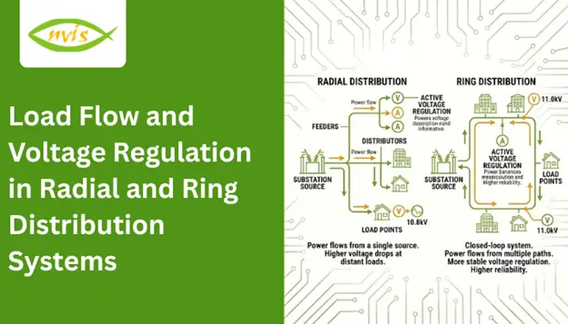
    In a ring distribution system, power may flow in multiple directions due to the closed-loop configuration. In contrast, in a radial system, power flows in only one direction from the source to the load.

    What is Voltage Regulation?

    Voltage regulation measures the change in voltage at the consumer terminal between no-load and full-load conditions.

    Voltage Regulation = (V_no-load − V_full-load) / V_full-load × 100%

    A well-designed ring and radial distribution system should maintain voltage variation within ±5% of the rated value.

    Radial and Ring Main Distribution System

    The Radial and Ring Main Distribution System training setup is designed to demonstrate the operating principles of both radial and ring main electrical distribution networks. A distribution system is an essential component of the electric power system, which connects high-voltage transmission networks to low-voltage service points of consumers. These systems should be designed so that voltage variation at consumer terminals does not exceed ±5% of the rated value.

    The Nvis training system provides in-depth practical learning support for manually developing and analytically assessing both ring and radial distribution system designs. Structured experiments and comparative studies help learners clearly understand the performance differences between the two systems.

    The system consists of a built-in DC variable power supply, including sufficient safety controls and digital metrology. The radial and ring main structures are covered in separate sections where students can study each system step-by-step and understand their operational significance.

    Product Features

    • Three digital DC voltmeters and three digital DC ammeters for precise measurement
    • Dedicated connection panels for both radial and ring main systems
    • Built-in DC variable power supply
    • Isolation transformer for enhanced operational safety
    • Exclusive and ergonomically designed control panel
    • Integrated lamp load holders
    • Clear diagrammatic representation for easy circuit connections

    Comparative View: Load Flow and Voltage Regulation

    Parameter

    Radial System

    Ring Distribution System

    Power Flow

    Single direction

    Bi-directional

    Voltage Drop

    Higher

    Lower

    Losses

    Higher

    Reduced

    Reliability

    Lower

    Higher

    Complexity

    Simple

    Moderate

    Load Flow in Distribution Systems

    Load flow, or power flow analysis, evaluates the operating condition of a distribution network. In a ring and radial distribution system, it determines:

    • Voltage magnitude at each bus
    • Phase angle at each bus
    • Active power (P) and reactive power (Q) flow
    • Line losses

    In a radial and ring main distribution system, load flow analysis ensures proper voltage levels, efficient power delivery, and reliable operation. It forms the foundation of effective planning, design, and performance optimization in any ring distribution system.

    Load Flow in Ring Distribution System

    Power Flow Characteristics

    A ring distribution system involves a closed-loop feeder configuration where power flows in both directions toward the load. Unlike the single power path in a radial setup, load current in a ring network is shared between two paths. With current shared between two paths, the current in each section is reduced, resulting in a more uniform voltage drop and lower overall line losses. The multi-path design of a ring distribution system enhances voltage stability and provides a more uniform voltage profile across all load points.

    Mathematical Considerations

    In a ring distribution system, electrical loops are closed. This means that Kirchhoff Voltage Law (KVL) needs to be met around every loop and loop current analysis is necessary. Ring systems require more complex iterative techniques for analysis, whereas radial systems can often be solved using simpler methods to determine voltage magnitude, phase angle, and power flow. The typical methods are the Newton-Raphson method, Gauss-Seidel method, and modified Forward-Backward Sweep method. These methods help in accurate analysis of load flow within a ring distribution system.

    Voltage Regulation in Ring System

    Since the current in a ring-type of distribution flows in two directions, the line current in each piece of the feeder is less. This results in reduced I²R losses and lower voltage drop across the network. Consequently, voltage regulation is better than in radial systems. The improved voltage profile and reliability of ring systems make them well suited for urban and industrial distribution networks where voltage stability is critical.

    Conclusion

    Performance parameters in any distribution network are load flow and voltage regulation which are paramount. Ring and radial distribution systems represent two different design philosophies with distinct operational characteristics.

    Radial systems are cheap, easy, and may be applied in sparsely populated regions but have greater voltage drops and reduced reliability.

    In contrast, the ring distribution system offers:

    • Improved voltage regulation
    • Reduced losses
    • Better reliability
    • Enhanced operational flexibility

    The choice between radial and ring main distribution systems depends on cost, load density, reliability requirements, and operational complexity.

    With the advent of smart grids and renewable integration, distribution systems are becoming intelligent, adaptive networks capable of maintaining excellent voltage profiles and efficient load flow performance.

    FAQs

    A ring and radial distribution system refers to two types of power distribution networks. A radial system has a single path from source to load, while a ring system forms a loop that allows power to flow in two directions.

    Load flow analysis helps calculate voltage levels, power flow, and line losses in a radial and ring main distribution system, ensuring safe and efficient operation.

    Voltage regulation is the change in voltage between no-load and full-load conditions. A good ring distribution system maintains voltage within ±5% of the rated value.

    A ring distribution system is more reliable because power can reach the load from two directions, reducing the chance of complete supply failure.

    Radial systems are commonly used in rural or low-load areas because they are simple, economical, and easy to maintain.

    Tags: radial and ring main distribution system, ring and radial distribution system, ring distribution system

    Relay Coordination Techniques for Over Current and Earth Fault Protection

    TL;DR –

    • This blog is designed for electrical engineers, protection engineers, power system professionals, engineering students, and technical trainers who want to understand current and earth fault relay systems and techniques of coordination in depth.
    • An overcurrent and earth fault relay protects electrical systems from overloads, short circuits, and ground faults by detecting abnormal current conditions and tripping breakers before damage occurs.
    • Proper techniques of coordination ensure selective tripping, only the relay nearest to the fault operates, preventing unnecessary outages and maintaining system stability.
    • Effective relay coordination involves data collection, fault current calculation, curve selection, pickup and time settings adjustment, TCC curve plotting, and thorough testing.
    • Earth Fault Relay Testing Systems provide hands-on training to study relay characteristics, connections, and performance verification, helping students and professionals build practical protection expertise.


    Modern power systems are designed to deliver electricity safely, reliably, and efficiently. However, electrical circuits are constantly exposed to disturbances such as short circuits, overloads, insulation failures, and ground faults. These faults, if not properly protected against, may cause equipment damage, fire hazards, and widespread outages.

    At the core of electrical protection systems is the over current and earth fault relay, a fundamental device that monitors abnormal current conditions and isolates faulty sections before damage escalates.

    Related Blogs –

    Over Current and Earth Fault Protection

    Electrical systems operate within specified current limits. Protection devices must respond promptly whenever current exceeds normal limits due to faults or abnormal conditions.

    Two of the most common fault types in power systems are:

    • Over current faults – caused by overloads or short circuits
    • Earth faults (ground faults) – caused when a conductor comes into contact with ground or grounded structures

    The over current and earth fault relay offers protection in both scenarios. It measures current on a line using current transformers (CTs) and triggers breaker tripping upon meeting preset thresholds.

    In multi-level distribution systems, relays are installed at feeders, transformers, busbars, and main incomers. If all relays trip simultaneously during a fault, the entire system may shut down unnecessarily.

    This is where techniques of coordination become critical.

    Earth Fault Relay Testing System

    The Earth Fault Relay Testing System provides hands-on exposure to protection devices used to prevent faults caused by earth leakage currents. Effective protection is essential to ensure the safety and reliability of electrical systems.

    Power systems make use of a number of protective devices, and studying how they work helps to use them in smarter ways and avoid system failures. Earth leakage current may cause excess heat and insulation degradation over time, and finally cause earth faults and sparking. An Earth Fault Relay senses leakage currents before they reach the preset threshold, thus safeguarding equipment and ensuring operational safety.

    Nvis provides an interactive learning environment that demonstrates the connection of an Earth Fault Relay in a transmission line and allows testing of its operation. Through practical demonstrations using Nvis systems, students gain hands-on experience in the application and testing of Earth Fault Relays in power systems.

    The Earth Fault Relay Testing System is an ideal educational platform for improving technical knowledge, practical training, and skill development among students and young professionals.

    Product Features

    • Inbuilt variable source
    • Large-font LCD display for clear visibility
    • Isolation transformer for safe operation
    • Durable and rugged panel design
    • Engineered with comprehensive safety considerations
    • Diagrammatic representation for easy connections

    Scope of Learning

    • Study and verification of Earth Fault Relay operating characteristics under different plug settings
    • Understanding the connection of an Earth Fault Relay in a transmission line
    • Practical testing procedures of an Earth Fault Relay

    Fundamentals of Over Current and Earth Fault Relays

    Overcurrent protection operates when current exceeds a predefined pickup value. Overcurrent may result from:

    • Overloads
    • Phase-to-phase short circuits
    • Three-phase faults

    Overcurrent relays are classified into:

    1. Instantaneous Relays – operate with no intentional delay
    2. Definite Time Relays – operate after a fixed delay
    3. Inverse Time Relays – operating time decreases as fault current increases

    Inverse time characteristics are widely used because they provide better discrimination.

     What Are Earth Fault Relays?

    Earth faults occur when current flows from phase conductors to ground due to insulation failure, cable damage, or equipment breakdown.

    Earth fault protection is essential because:

    • Ground faults may produce lower fault currents than phase faults
    • They can cause severe damage if undetected
    • Personnel safety is at risk

    Earth fault relays are typically more sensitive and operate at lower pickup settings than phase overcurrent relays.

    Combined Over Current and Earth Fault Relay

    A modern over current and earth fault relay integrates both protection functions into a single numerical device. Benefits include:

    • Reduced panel space
    • Improved accuracy
    • Multiple characteristic curve options
    • Communication capability
    • Event recording and fault analysis

    Importance of Relay Coordination

    Relay coordination ensures that only the protection device closest to the fault operates, while upstream devices remain active unless backup protection is required. When an over current and earth fault relay is properly coordinated, unnecessary power interruptions are avoided, and system stability is maintained.

    Objectives of Coordination

    • Selectivity – Isolate only the faulty section
    • Reliability – Operate correctly during faults
    • Speed – Clear faults quickly
    • Sensitivity – Detect low-level fault currents
    • Backup Protection – Provide redundancy if primary protection fails

    Step-by-Step Relay Coordination

    Systematic relay coordination study is critical in order to make sure that the over current and earth fault relay can work with an acceptable level of selectivity, reliability, and speed. Effective techniques of coordination follow a systematic engineering approach, as described below.

    Step 1: Data Collection

    The first step is collecting accurate system data. It comprises the single-line diagram (SLD), transformer ratings and impedance, cable sizes and lengths, CT ratios with accuracy class, and short-circuit levels available at different buses. Accurate data ensures reliable setting calculations and proper coordination.

    Step 2: Fault Current Calculation

    Then determine the anticipated fault currents in various system points. These are normally the three-phase faults, the line-to-line faults and the earth faults. Fault current values are used to set relay pickup settings and also assist in setting the time delays required in selective operation.

    Step 3: Select Relay Characteristics

    Select appropriate inverse time characteristics depending on the behavior and protection needs of a system. The most common are standard inverse, very inverse and extremely inverse curves. Selecting the correct curve is a critical aspect of relay coordination.

    Step 4: Set Pickup Current

    Relay pickup current is usually adjusted to between 125 and 150 percent of full load current. This prevents unnecessary tripping under normal conditions while ensuring reliable operation during fault conditions.

    Step 5: Set Time Multiplier

    Adjust the time multiplier (time dial setting) to maintain adequate coordination margin between downstream and upstream relays. This guarantees that the nearest relay will clear the fault first with the upstream devices acting as a backup.

    Step 6: Plot TCC Curves

    Time-Current Characteristic (TCC) curves are plotted using professional coordination software such as ETAP, DIgSILENT, or SKM. These plots help visually verify proper separation and coordination between relay curves.

    Step 7: Verify and Test

    Finally, verify the settings through secondary injection testing and commissioning validation. During testing, it is important to make sure that the over current and earth fault relay functions precisely as desired when the fault conditions are simulated.

    Conclusion

    Electrical protection is not merely about installing relays; it is about coordinating them to operate selectively and precisely. With a correctly implemented protection scheme, only the faulty part of the system is disconnected and the rest of the system keeps on functioning. Such performance is achieved only through systematic application of proven coordination techniques.

    When properly coordinated, engineers achieve selective fault isolation, shield major equipment of thermal and mechanical harm, reduce expensive downtime, and enhance the general reliability of the system greatly. These advantages have vital roles in ensuring continuity of operation within industrial, commercial and utility power systems.

    The over current and earth fault relay remains one of the most essential components of modern electrical protection systems. It offers reliable fault detection, quick clearance, and efficient backup protection when programmed using a thorough and systematic coordination examination. Relay coordination is not a luxury in modern power networks—whether in a manufacturing facility or a smart grid, it is a necessity for ensuring a robust and future-proof electrical system.

    FAQs

    An over current and earth fault relay is a protection device used in power systems to detect excessive current and ground (earth) faults. It monitors current through current transformers (CTs) and trips the circuit breaker when preset limits are exceeded, protecting equipment from damage.

    Proper techniques of coordination ensure that only the relay closest to the fault operates first, while upstream relays act as backup. This prevents unnecessary outages and maintains system stability.

    The key objectives include selectivity, reliability, speed, sensitivity, and backup protection. These ensure faults are cleared quickly without affecting healthy parts of the electrical system.

    Overcurrent protection responds to excessive phase currents caused by overloads or short circuits, while earth fault protection detects leakage current flowing to ground due to insulation failure or conductor contact with earth.

    TCC curves show the relationship between fault current magnitude and relay operating time. They are used in coordination studies to ensure proper separation between upstream and downstream relay settings.

    Tags: over current and earth fault relay, techniques of coordination