







TL;DR
- This blog is for electrical and electronics engineering students, freshers, and GATE, SSC JE, and RRB JE aspirants who want a clear, practical understanding of three phase AC voltage controller waveforms.
- A three phase AC voltage controller uses six thyristors to control RMS voltage delivered to a three phase load without changing supply frequency.
- output waveform depends on firing angle alpha, which falls into three distinct conduction modes, each producing a different chopped voltage shape.
- A worked numerical example ties waveform theory to real RMS voltage and power calculations that students can reproduce in exams and labs.
- The topic carries real weight in GATE Power Electronics and in India’s growing power electronics, EV, and industrial automation job market.
A three phase AC voltage controller is a circuit that controls the RMS value (effective value) of AC voltage supplied to a three phase load without changing the supply frequency. It uses six thyristors, two connected in anti parallel per phase, fired at a controlled delay angle after each natural commutation point. This blog explains how circuit operates, breaks down three conduction modes that shape its output waveforms, and connects theory to Indian industry applications, GATE exam relevance, and career paths in power electronics.
Also read
- Sumpner’s Test of Transformer: Working Principle, Circuit, and Procedure
- What Is a Radial Distribution System? Working Principle & Advantages
- Ring Main Distribution System: Working Principle, Advantages
What Is a Three Phase AC Voltage Controller
Think about a fan regulator in your home. When you turn the knob, you are not changing the frequency of the AC supply coming into your house. You are simply controlling how much of each voltage cycle actually reaches the fan motor. Turn it down, and the fan gets a smaller “slice” of each cycle. Turn it up, and it gets more.
A three phase AC voltage controller does exactly this, but at an industrial scale, across three phases simultaneously, and using thyristors instead of a mechanical knob. Instead of a ceiling fan, load could be a large induction motor, an industrial heater bank, or a set of high power lamps drawing current from a three phase supply.
The main idea is simple. The controller does not convert AC into DC. It works only with AC and controls how much voltage reaches the load. It just “chops” each half cycle of input waveform, letting through only a controlled portion of it, so RMS voltage reaching load can be adjusted smoothly from close to full supply voltage down to nearly zero.
Because it controls AC voltage without changing it into DC, this circuit is also called an AC-to-AC converter or an AC voltage regulator. The primary keyword here, three phase AC voltage controller, refers to this exact family of circuits, and understanding its waveform behavior is the foundation for everything else in this topic.
How Circuit Works: Thyristors, Firing Angle and Natural Commutation Point
Before learning the waveforms, you should understand three basic ideas: a thyristor pair, the firing angle, and the natural commutation point.
Each phase of the controller uses two thyristors connected back to back, or antiparallel. One thyristor conducts during the positive half cycle of that phase’s voltage, and the other conducts during the negative half cycle. This antiparallel pairing is necessary because a single thyristor can only conduct current in one direction, but an AC load needs current flowing both ways across a full cycle.
A natural commutation point is the moment when one thyristor turns off and another takes over because the AC supply changes direction. It serves as the reference point from which the firing angle is measured. For a three phase system, this point repeats every 60 degrees because there are six such transitions in every 360 degree cycle, one for each thyristor.
The firing angle (α) is the delay between the natural commutation point and the moment the thyristor is switched on. If alpha is small, thyristor turns on almost as soon as it is able to, and load receives nearly full voltage. If alpha is large, thyristor turns on late in cycle, so it conducts for a shorter time, and load receives a smaller RMS voltage.
Two more terms matter here. A thyristor turns off automatically the moment its current falls to zero, which is called natural or line commutation. And for a thyristor to actually fire, two conditions must be true at the same time: its anode voltage must be higher than its cathode voltage, and a gate pulse must be present. Instead of sending one short gate pulse, engineers often send several pulses over a short period. This makes sure the thyristor turns on even if the exact switching time changes slightly and a single narrow pulse might be missed.
Three Phase AC Voltage Controller Waveforms: Mode I, II and III Explained
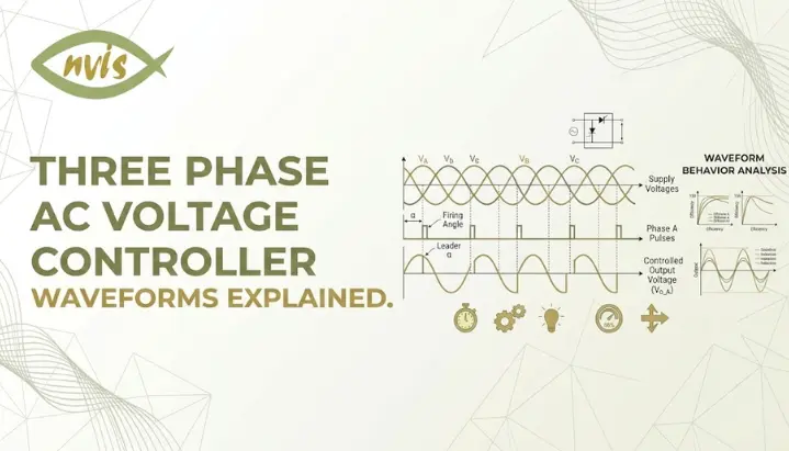
This is the most important part of the topic. Many textbooks become difficult here because they start with maths instead of explaining the idea first. Before math, picture what is physically happening: as you increase firing angle alpha, fewer thyristors are conducting at any given instant, and shape of chopped waveform changes character three distinct times. Power electronics engineers label these three characters Mode I, Mode II, and Mode III.
Mode I: 0° ≤ α < 60°
In this range, the controller behaves almost like an uncontrolled circuit. At any instant, either two or three thyristors are conducting simultaneously. Because nearly full waveform gets through, output closely resembles undelayed sine waves, only slightly clipped near the start of each half cycle. This mode delivers the highest RMS output voltage range, from full supply voltage down to roughly 96 to 97 percent of it as alpha approaches 60 degrees.
Mode II: 60° ≤ α < 90°
Here behavior changes noticeably. At any given moment, exactly two thyristors conduct, one from each of two different phases. There is no longer a window where three thyristors conduct together. The output waveform now has small gaps where the voltage becomes zero before the next thyristor turns on. This is the transition zone where the chopped nature of the waveform becomes visually obvious on an oscilloscope.
Mode III: 90° ≤ α < 150°
In this final mode, the thyristors do not conduct continuously. There are short periods when no current flows. Sometimes two thyristors conduct together, and sometimes none conduct at all, leaving load voltage at zero for stretches of cycle. output RMS voltage drops sharply through this range, falling from around 70 percent of supply voltage at alpha equals 90 degrees to nearly zero as alpha approaches 150 degrees, which is the theoretical extinction point for a purely resistive star connected load.
Worked Numerical Example
Suppose a three phase, star connected, three wire AC voltage controller supplies a balanced resistive load with R equal to 10 ohms, connected to a 380 volt line to line, 50 Hz supply, and firing angle alpha is set to 30 degrees.
Since α = 30° is in Mode I, almost the full supply voltage reaches the load. Phase voltage Vm here corresponds to a line to neutral RMS value of about 220 volts. At alpha equals 30 degrees, standard control characteristic tables for this configuration show output RMS phase voltage is close to 98.5 percent of supply phase voltage, giving an output of roughly 216 to 217 volts RMS per phase.
Using this output voltage, RMS load current per phase works out to approximately Vo,rms divided by R, and output power per phase follows from Vo,rms squared divided by R. For a balanced three phase load, total output power is simply three times per phase power. This is exactly the kind of calculation that appears in GATE and university exam papers, so working through it by hand, rather than only reading derivation, builds real exam readiness.
Now compare this to alpha equals 90 degrees on the same circuit. System shifts into Mode III, and output RMS voltage collapses to roughly 70 percent of supply value, which more than halves delivered power compared to alpha equals 30 degrees, since power scales with square of voltage.
Comparison Table: Single Phase vs Three Phase AC Voltage Controller
| Parameter | Single Phase AC Voltage Controller | Three Phase AC Voltage Controller |
| Thyristors required | 2 (one antiparallel pair) | 6 (two per phase) |
| Firing angle range for full control | 0° to 180° | 0° to 150° for resistive star load |
| Number of conduction modes | Not applicable | Three distinct modes (I, II, III) |
| Typical applications | Lamp dimming, single phase heaters, small fan regulators | Three phase motor speed control, industrial heaters, soft starters |
| Harmonic content | Odd harmonics present | Odd harmonics present, triplen harmonics depend on connection type |
| Control complexity | Simple, single firing circuit | More complex, six coordinated firing circuits |
| Common connection types | Direct or with transformer | Star three wire, star four wire, or delta connected |
Applications of Three Phase AC Voltage Controller in Industry
Three phase AC voltage controllers are used in industries where AC power needs to be controlled smoothly without converting it into DC. The most common application is limited speed control of induction motors, mainly in fan and pump applications where torque requirements permit voltage control used in fans, pumps, and conveyor systems, where the controller adjusts voltage fed to the stator to vary motor speed and torque within limits.
Industrial heating systems are another major use case, particularly in furnaces and ovens where precise temperature control depends on regulating RMS voltage delivered to heating elements rather than switching them fully on or off. Static VAR compensators and soft starters for large motors also rely on the same underlying phase control principle, using controlled firing of thyristors to limit inrush current during motor startup.
Lighting control for large scale industrial or commercial installations, where dimming needs to happen uniformly across all three phases, is a further application area, along with certain classes of certain thyristor-based AC voltage regulators used in industrial power control with sensitive equipment.
India Context: Industry, Employers and Regulatory Landscape
In India, three phase AC voltage controllers and a broader family of AC to AC power electronic converters are core building blocks in sectors that the government has been actively pushing: renewable energy integration, industrial automation, and electric mobility. Companies such as BHEL, L&T, Siemens, ABB, and Crompton Greaves design and manufacture equipment that relies on this class of thyristor based control, particularly for motor drives and industrial power quality equipment.
Government policies also play an important role. Bureau of Energy Efficiency and broader push toward energy efficient industrial motors under India’s national programs have increased demand for engineers who understand voltage and speed control at power electronics level, not just at mechanical or control systems level. As India’s manufacturing sector modernizes under initiatives like Make in India and Production Linked Incentive schemes for electronics and semiconductor manufacturing, practical skill of reading and designing around thyristor controlled AC waveforms remains directly employable.
Public sector undertakings such as NTPC, PowerGrid, and BHEL, along with private players expanding into EV charging infrastructure and grid scale power electronics, continue to hire electrical engineers with a solid grounding in power electronics fundamentals, of which three phase AC voltage controller is a standard part of undergraduate and GATE syllabus.
Career and Salary Guidance in Power Electronics (India, 2026)
The average salary for a Power Electronics Engineer in India currently stands close to eight lakh rupees per year, with a typical range roughly between five and a half lakhs and eleven and a half lakhs annually depending on experience and employer. At fresher level, entry into government and PSU roles through GATE typically corresponds to a fixed pay scale in the six to twelve lakh range, while private sector roles in EV and semiconductor adjacent power electronics work can pay significantly more once a few years of hands-on experience are added.
Engineers who learn power electronics, motor drives, and battery management systems usually have better career opportunities for EV and grid integration space are seeing some of the fastest salary growth in the Indian market right now, with experienced roles in this niche commanding substantially higher packages than generalist electrical engineering positions. Renewable energy, industrial automation with PLC and SCADA skills, and defence and aerospace power systems roles round out strongest career tracks for someone who has built a genuine understanding of AC voltage control and related power conversion topics.
For students planning their career path, practical advice is straightforward: a strong grip on power electronics fundamentals such as three phase AC voltage controller, combined with hands on simulation experience using tools like MATLAB or PSIM, and a competitive GATE score, opens doors to both well established PSU route and faster growing private sector opportunities in EV and renewable energy companies.
GATE / SSC JE / RRB JE Exam Relevance
Power Electronics is one of higher weightage sections in GATE Electrical Engineering paper, and AC voltage controllers fall squarely within its syllabus alongside rectifiers, choppers, and inverters. Questions on this topic typically test three things: ability to identify correct conduction mode for a given firing angle, ability to compute RMS output voltage or output power for a stated alpha, and conceptual understanding of thyristor firing and commutation.
For SSC JE and RRB JE aspirants, depth of numerical analysis expected is usually lower than GATE, but conceptual questions on thyristor operation, purpose of firing angle, and basic difference between single phase and three phase AC voltage controllers appear regularly in power electronics and basic electrical engineering sections of these exams.
For exams, first learn the three conduction modes and their firing angle ranges. Many questions can be answered by identifying the correct mode and their alpha ranges first, since a large share of objective questions can be answered correctly just by recognizing which mode a given firing angle falls into, without needing to solve full RMS voltage integral under exam time pressure.
Conclusion
A three phase AC voltage controller regulates AC power the same way a fan regulator does, just scaled up to industrial three phase loads using six coordinated thyristors instead of a single mechanical dial. The output waveform passes through three distinct conduction modes as firing angle alpha increases from 0 to 150 degrees, and recognizing these modes is key skill for both exam problems and real circuit analysis. This topic is important because it is asked in GATE exams and is also widely used in industry in India’s growing power electronics, EV, and industrial automation sectors, which makes it worth mastering properly rather than memorizing formulas. Work through worked examples in this blog on paper, try varying firing angles yourself, and you will find underlying logic becomes intuitive far faster than equations alone suggest.
FAQs
A rectifier converts AC input into DC output, while a three phase AC voltage controller keeps output in AC form and only adjusts its RMS magnitude. Both use thyristors and firing angle control, but the controller never creates a DC link.
Each of three phases needs an antiparallel pair of thyristors to handle both positive and negative half cycles of that phase’s voltage, since a single thyristor conducts in only one direction. Three phases multiplied by two thyristors each gives six total.
Mode I covers firing angles from 0 to 60 degrees where two or three thyristors conduct together, Mode II covers 60 to 90 degrees where exactly two thyristors conduct at a time, and Mode III covers 90 to 150 degrees where conduction becomes intermittent and can drop to zero.
For a star connected three wire configuration with a balanced resistive load, practical extinction point is around 150 degrees, beyond which output voltage effectively falls to zero.
Yes, it falls under Power Electronics section of GATE EE syllabus, which typically carries significant weightage, and questions frequently test conduction mode identification and RMS output voltage calculations.
They are commonly used for three phase induction motor speed control, industrial heating and furnace applications, soft starters for large motors, and certain lighting and power quality applications in manufacturing plants across companies like BHEL, L&T, Siemens, and ABB.