





TL;DR
- This blog is for engineering students, freshers, and GATE/SSC JE/RRB JE aspirants who keep hearing terms UART, SPI, and I2C but have never had anyone explain what a serial communication protocol actually is or why three different ones even exist.
- The core problem beginners face is jargon overload. Terms like master slave, baud rate, and clock synchronization get thrown around before anyone explains what problem these protocols are solving in the first place.
- Every microcontroller needs a way to “talk” to sensors, displays, memory chips, and other boards, and a serial communication protocol is simply an agreed set of rules that defines how devices exchange data and coordinate communication reliably.
- UART, SPI, and I2C each trade off speed, wiring, and complexity differently, and the right one to learn first depends on what you build most often as a beginner, not on which is “best” overall.
- If you are starting out, learn UART first for its simplicity, then SPI for speed critical projects, then I2C once you are comfortable connecting multiple sensors to a single microcontroller.
All electronic devices that can “talk” to one another, be they one device sending temperature data to a microcontroller, or a laptop loading code onto an Arduino, use some form of serial communication protocol. The knowledge of UART, SPI and I2C is one of the basic and most useful skills in embedded system design, as almost all embedded system projects require UART, SPI or I2C to transfer data between chips.
It explains what a serial communication protocol is, how UART, SPI and I2C work, what a USB connection is and which is best to learn first if you are new to programming a serial communication protocol. There are also worked examples along the way and a side by side comparison table to make the topic easy to understand, along with information on the importance of the topic for exams like GATE, SSC JE, RRB JE and embedded systems jobs in India.
Also read,
- Swinburne Test of DC Machine: Procedure & Working
- Ward Leonard Method of Speed Control: Working Principle, Advantages and Disadvantages
- Three Phase AC Voltage Controller Waveforms: Modes & Working
What Is Serial Communication Protocol?
Suppose two people want to talk to each other but one person speaks in short sentences and the other wants it back-and-forth. If there is no set system to turn taking, then talk becomes noise. When electronic devices must share data, they have the same issue and there is an agreed upon protocol of rules that stops that noise from occurring.
Technically, a serial communication protocol is a way of transmitting bits (data) sequentially over a single wire or a few wires, rather than simultaneously over numerous wires all in parallel. This one bit at a time approach is known as serial communication, and is the opposite of parallel communication, which sends multiple bits at once over multiple lines, like several cars driving on a multi-lane highway.
Why is serial communication so widely used in modern microcontroller designs, even though parallel interfaces can transfer multiple bits simultaneously? This reduces the amount of wires that need to be added to a PCB, making PCB layouts easier to create, reducing costs and making it less likely to cause signal interference from further distances as circuits become smaller and more densely populated. That’s why UART, SPI, and I2C (all serial protocols) are the most prevalent means of communication between microcontrollers and peripherals today.
Two concepts should be fixed in the early stages of UART, SPI, and I2C before you get into dealing with these protocols individually: transmission and clock. The mode of transmission is just a description of how data may be transmitted. Data can flow only one way through Simplex, similar to a radio broadcast. Half duplex – both ways, not at once, like a walkie/talkie. Full duplex means two-way communication, as in a telephone call where both parties can talk and hear each other at once.
Clock synchronization means whether they have a common timing signal on which to synchronize them to know when to read each bit. With synchronous protocols, a dedicated clock wire ensures that all devices remain in perfect synchronization. Asynchronous protocols do not use the clock wire at all, and instead each device agrees in advance to a known speed, and assumes that they will stay in sync. This is one of the key differences between UART, SPI, and I2C. UART is asynchronous, while SPI and I2C are synchronous. They also differ in wiring, addressing, duplex mode, speed, and how multiple devices are connected.
UART: Simplest Serial Communication Protocol
Imagine that two friends are passing notes back and forth, but neither says “I’m about to write a note”. The system runs smoothly without a shared clock between them as long as both of them have agreed in advance on the speed at which they will read and write. This is basically UART’s work.
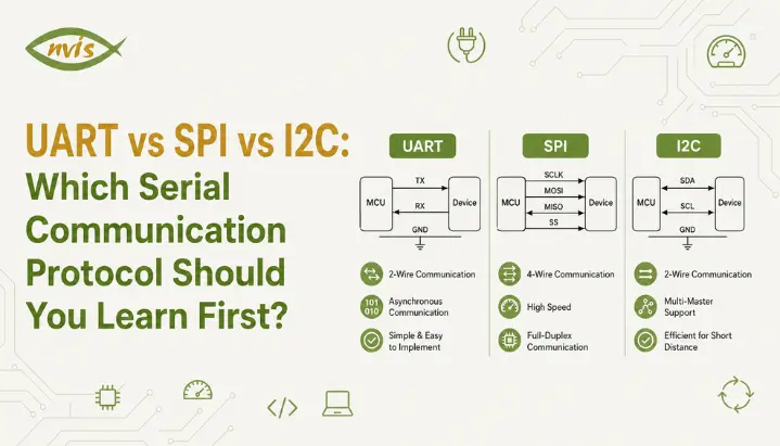
UART is an acronym for Universal Asynchronous Receiver Transmitter, and because it requires just a few components, it is considered to be an introduction to serial communications into microcontroller circuits. A basic UART connection commonly uses two signal lines, TX and RX, along with a shared ground. Two devices cross connect their transmit and receive lines and share a common ground with the TX pin of one device connected to the RX pin of the other.
Asynchronous is a key word. There is no special clock wire for UART. Instead, the sending and receiving devices are configured to use the same baud rate in advance. Each device internally uses that agreed setting to determine when to sample each bit, and each device internally uses that speed to time when to sample each bit. Each UART character or frame typically begins with a start bit, followed by the data bits and optional parity bit, and ends with one or more stop bits but, in the absence of a common clock, the receiving UART knows when each byte starts and ends.
The following is a quick worked example of something which frequently appears in exam-style questions. When the UART is programmed to run at 9600 baud, the time to send one bit is called bit time, and is given by:
Bit time = 1 / Baud rate = 1 / 9600 = 0.0001042 seconds ≈ 104.2 microseconds
Let’s assume we’re using a standard 10-bit frame, where each frame contains 1 start bit, 8 data bits, and 1 stop bit, and that we’re sending one whole frame at a time. In this case, the total number of bits is 10, and the time to send one complete frame is about 1.042 milliseconds. Baud-rate and bit-time calculations are useful practice for students studying serial communication and microcontroller timing, and may be relevant to technical-exam questions depending on the exam and syllabus.
The greatest virtue of UART is its simplicity. It is point-to-point, that is, it connects only two devices – is ideal for debugging via serial monitor, connecting GPS modules or talking to Bluetooth modules such as HC 05. What makes it the least desirable is its point to point character. However, unlike SPI and I2C, UART is difficult to scale to multiple devices on the same bus and if the baud rate is not the same, data is completely garbled.
SPI: Built for Speed
Now picture a strict orchestra conductor keeping every musician perfectly in time with a baton. Nobody plays a note unless the conductor’s beat says so, and because everyone follows the same beat, the whole orchestra can play remarkably fast without falling out of sync. SPI works on this same principle of a shared, dedicated timing signal.
SPI stands for Serial Peripheral Interface, and unlike UART, it is a synchronous protocol, meaning it uses a dedicated clock line so every connected device reads and writes data in perfect step with each clock pulse. The shared clock allows the receiver to sample data at precisely defined clock edges. SPI also has relatively little protocol overhead, which allows many implementations to operate at much higher data rates than typical UART and I2C connections.
An SPI connection typically uses four lines: MOSI (Master Out Slave In) carries data from controller to peripheral, MISO (Master In Slave Out) carries data back from peripheral to controller, SCK is shared clock line, and SS or CS (Slave Select or Chip Select) tells a specific peripheral device that it is being addressed. Because SPI uses a dedicated select line per device, a single controller can talk to multiple peripherals on the same bus just by toggling which chip select line is active.
This full-duplex design, combined with low protocol overhead, allows many SPI implementations to operate at several megabits per second or much higher, depending on the microcontroller, peripheral, wiring, and signal integrity. This is exactly why SPI shows up everywhere speed genuinely matters: driving SD cards, refreshing TFT displays, and streaming data from high sample rate sensors like accelerometers.
The main trade-off is wiring and scalability at the pin level. Every additional SPI peripheral needs its own dedicated chip select line, so a design with many sensors can quickly run out of available microcontroller pins. SPI also has no formal acknowledgment mechanism, so if a peripheral fails to respond, there is no built-in way for the controller to know something went wrong.
I2C: Many Devices, Few Wires
Imagine a classroom where the teacher can call out a specific student’s name before asking a question, and every student in the room hears the question but only one called upon responds. Everyone shares the same “wire” of conversation, yet the system stays organized because each student has a unique identity. This is essentially how I2C manages to connect many devices using very few wires.
I2C, short for Inter Integrated Circuit and often pronounced “I squared C,” is a synchronous serial communication protocol that uses the same two bus lines, SDA and SCL, for multiple connected devices, subject to address availability and electrical bus limitations. These two lines are SDA (Serial Data), which carries actual data, and SCL (Serial Clock), which keeps every device on the bus synchronized to the same timing.
The mechanism that makes this scalability possible is device addressing. I2C devices can use 7-bit or 10-bit addresses. Although a 7-bit address field provides 128 possible values, some addresses are reserved, and address conflicts can occur when multiple devices use the same fixed address of the specific device it wants to talk to. Every device on a shared bus receives this address, but only the device whose address matches actually responds, similar to the classroom example above. I2C uses 7-bit or 10-bit addressing. Although a 7-bit address field provides 128 possible values, some addresses are reserved, so the number of usable device addresses is lower. In practice, the number of devices is also limited by bus capacitance, address conflicts, and the electrical characteristics of the bus.
I2C typically operates at up to 100 kbps in standard mode and up to 400 kbps in fast mode, noticeably slower than SPI, and I2C is not full duplex: data is transferred over the shared SDA line, with the controller and target taking turns transmitting according to the bus protocol, even though communication can switch directions when needed. What I2C gives up in raw speed, it makes up for in wiring efficiency, which is why it is widely used in projects involving multiple low-speed sensors, such as temperature sensors, real time clocks, EEPROMs, and accelerometers, all sharing same SDA and SCL lines.
I2C does have real limitations worth knowing. Because I2C devices use open-drain or open-collector outputs, the SDA and SCL lines are pulled high through external pull-up resistors. Devices actively pull the lines low when transmitting. This arrangement allows multiple devices to share the same bus without directly driving the lines high against one another.
USB Serial Communication Protocol: How It Connects to UART
A common point of confusion for beginners is the relationship between UART and USB, especially since the keyword “USB serial communication protocol” often gets searched by people expecting them to be interchangeable. They are related, but they are not the same thing, and understanding differences clears up a lot of confusion when working with development boards.
When you plug an Arduino or another development board into a laptop over USB, the board may use a USB-to-UART bridge such as a CP2102, CH340, or FTDI device to convert between USB and UART such as a CP2102, CH340, or FTDI device converts USB communication from the computer into UART signals for the microcontroller that microcontroller’s UART actually understands. Your operating system usually shows this connection as a COM port on Windows or a /dev/ttyUSB or /dev/ttyACM device on Linux, even though physically you plugged in a USB cable.
USB itself is a far more complex, host centric protocol built for plug and play convenience, supporting device enumeration, much higher speeds ranging from 1.5 Mbps in early versions to multiple Gbps in modern versions, and even ability to deliver power to connected devices. UART, by contrast, remains a simple two wire asynchronous protocol running quietly underneath, doing actual byte level framing that your microcontroller’s UART peripheral was built to handle.
For many development boards, a USB-to-UART bridge connects the computer’s USB interface to the microcontroller’s UART. However, some modern microcontrollers and development boards provide native USB, so USB communication does not necessarily involve UART On boards that use a USB-to-UART bridge, the USB connection provides the computer-side interface while UART handles communication on the microcontroller side you already learned about earlier in this guide.
UART vs SPI vs I2C: Side by Side Comparison
| Parameter | UART | SPI | I2C |
| Full Form | Universal Asynchronous Receiver Transmitter | Serial Peripheral Interface | Inter Integrated Circuit |
| Clock Signal | None (asynchronous) | Yes (synchronous) | Yes (synchronous) |
| Wires Needed | 2 (TX, RX) | 4 (MOSI, MISO, SCK, SS) | 2 (SDA, SCL) |
| Devices Supported | 2 (point to point) | Many, limited by chip select pins | Up to 127+ using addressing |
| Typical Speed | Up to 115200 bps commonly | Up to 10 Mbps or higher | 100 kbps to 400 kbps typically |
| Duplex Mode | Full duplex | Full duplex | Half duplex |
| Complexity | Lowest | Moderate | Moderate to high with multiple devices |
| Common Use Case | Debugging, GPS, Bluetooth modules | Displays, SD cards, high speed sensors | Multiple sensors, EEPROMs, RTCs |
Reading this table, a clear pattern emerges. UART wins on simplicity and is genuinely the easiest serial communication protocol to understand from scratch. SPI wins decisively on speed whenever a project genuinely needs it. I2C wins on wiring efficiency the moment a project grows beyond two or three connected devices. None of them is universally “better,” which is exactly why real embedded systems, from a simple Arduino weather station to a full scale industrial control board, routinely use all three protocols together, each handling part of the job it is best suited for.
Serial Communication in Microcontroller Projects: Where Each Protocol Fits
Understanding theory is one thing, but seeing how UART, SPI, and I2C actually show up together inside a real microcontroller project makes choice far more intuitive. Consider a typical IoT weather station built around an ESP32 or Arduino board, a genuinely common beginner project across Indian engineering colleges.
Many development boards use UART for serial debugging, and some use a USB-to-UART bridge for programming as well. However, some modern boards use native USB or other interfaces for programming, and many development boards provide a serial-monitor connection through USB for convenient debugging. If the project includes a small OLED or TFT display to show live temperature and humidity readings, that display may use SPI, especially when higher data-transfer rates are useful for refreshing the screen, because refreshing a screen quickly benefits enormously from SPI’s higher speed. Meanwhile, actual temperature, humidity, and pressure sensors, such as the BMP280 and many I2C-compatible sensors, are frequently connected over I2C. Some sensors, such as the DHT11/DHT22, use their own single-wire-style communication interface instead, since a project might eventually add two, three, or more sensors, and I2C lets every one of them share same two SDA and SCL wires without consuming extra microcontroller pins.
This pattern, UART for debugging, SPI for display, I2C for sensors, repeats across an enormous number of real embedded systems in industry, from consumer electronics to automotive dashboards to industrial monitoring equipment. Recognizing this pattern early is far more useful for a beginner than trying to memorize which protocol is “fastest” or “best” in isolation, because in practice, the answer is almost always all three, each doing a different job.
Which Serial Communication Protocol Should You Learn First?
If you are a beginner staring at UART, SPI, and I2C for the first time, wondering where to actually start, the honest answer is to learn them in that exact order, and here is the reasoning behind it.
Start with UART because it has the fewest moving parts. With just two wires and no shared clock to configure, UART lets you focus entirely on core ideas like baud rate, start and stop bits, and asynchronous timing without getting distracted by addressing schemes or multiple chip select lines. Nearly every beginner’s first “real” embedded systems project, printing values to a serial monitor, already uses UART, so you are likely to encounter it naturally within your first week of working with any microcontroller.
Move to SPI next, once UART feels comfortable. SPI introduces the idea of a shared clock and multiple peripherals through chip select lines, both of which build directly on concepts you already understand from UART, just with an added synchronous twist. Working with an SPI display or an SD card module is a natural next project, and it teaches you why a dedicated clock line matters for speed in a way that reading about it never quite does.
Finish with I2C, because it is conceptually the most involved of three despite needing fewest wires. Understanding device addressing, half duplex data flow, and how multiple devices share a single bus without colliding is easier to grasp once UART and SPI have already built your intuition for synchronous versus asynchronous communication and for how a controller distinguishes between devices. I2C is also where most beginners start building genuinely multi sensor projects, so having UART and SPI fundamentals already in place makes debugging I2C issues far less frustrating.
This progression, UART, then SPI, then I2C, is not an arbitrary suggestion. It provides a practical learning progression from simpler point-to-point communication to synchronous and then multi-device bus communication, and it is also a practical order that many beginner-focused embedded systems courses may use, which makes it a genuinely practical study path rather than just a beginner friendly opinion.
Why This Topic Matters for GATE, SSC JE, and RRB JE Aspirants
Serial communication concepts can be useful for engineering competitive exams because topics related to microprocessors, microcontrollers, interfacing, and communication may include questions involving data transmission, timing, and interfacing, which makes mastering UART, SPI, and I2C valuable well beyond the lab.
In GATE Electronics and Communication syllabus, questions on serial communication typically appear under microprocessors and microcontrollers, often testing baud rate calculations, bit time, and framing formats exactly like the worked example covered earlier in this guide. UART timing, baud rate, and bit-time concepts can be useful areas to practice for questions related to microprocessors and microcontrollers.
For RRB JE Electronics and Communication candidates, the technical section places significant weight on microprocessors, communication engineering, and hardware interfacing topics, all of which draw directly on the same UART, SPI, and I2C fundamentals covered here. SSC JE candidates preparing for the electronics stream face a very similar pattern, with related concepts that may be relevant to the microprocessors, microcontrollers, communication, and electronics topics covered in these examinations, depending on the specific syllabus and paper.
Beyond direct exam questions, interviewers at PSUs and private embedded companies alike frequently ask candidates to explain practical differences between UART, SPI, and I2C during technical rounds, since it is considered fundamental embedded systems knowledge. Being able to explain not just definitions but why behind each protocol’s design, exactly the approach this guide has taken, tends to stand out far more than a memorized comparison table during an actual interview.
Career Relevance: Embedded Systems Roles in India
Serial communication protocols form part of the absolute foundation for embedded systems careers in India, and demonstrating comfort with UART, SPI, and I2C can help candidates perform better in technical interviews and demonstrate practical embedded-systems knowledge at both PSUs and private companies.
Government and public sector opportunities remain a major draw for many engineering graduates, with organizations like ISRO, DRDO, BEL, and BHEL regularly hiring engineers into roles where embedded hardware knowledge, including serial communication interfacing, is directly tested during technical interviews and sometimes even written exams. These roles typically require qualifying through GATE scores or dedicated PSU recruitment exams, which is exactly why exam relevance covered in the previous section connects so directly to long term career outcomes.
On the private sector side, embedded systems engineering in India offers a genuinely strong salary trajectory for those who build solid fundamentals early. Entry level embedded engineers typically start in the range of 3 to 8 LPA depending on company and city, with automotive Tier 1 suppliers and semiconductor firms often offering higher end of that range to strong freshers. As experience grows, mid level embedded engineers with 3 to 6 years of experience commonly earn between 8 and 14 LPA, and senior embedded architects at companies working on semiconductors or automotive systems can reach 20 to 35 LPA or beyond, particularly as India’s semiconductor and electric vehicle sectors continue expanding under initiatives like PLI scheme for semiconductor manufacturing.
Recruiters across this spectrum, from PSUs to automotive companies to pure semiconductor firms, consistently list UART, SPI, and I2C interfacing as baseline expected knowledge for embedded roles, right alongside Embedded C and microcontroller fundamentals. Building genuine hands on familiarity with all three protocols during your college years, rather than memorizing them night before an interview, is one of more reliable ways to stand out early in an embedded systems career.
Conclusion
Serial communication protocols might seem like a dense, jargon heavy topic at first glance, but at their core, UART, SPI, and I2C are simply three different answers to the same basic question: how should two or more electronic devices reliably exchange data using as few wires as possible. UART keeps things simple with just two wires and no shared clock, SPI trades extra wiring for serious speed through a dedicated clock line, and I2C sacrifices some speed to let many devices share just two wires through unique addressing.
If you are just starting out, the clearest path forward is to learn UART first, move to SPI once you are comfortable, and finish with I2C. This order matches how conceptual complexity actually builds across three protocols, and it can provide a practical progression for students learning embedded communication interfaces. Beyond the classroom, this same knowledge directly feeds into GATE, SSC JE, and RRB JE technical sections, and it remains one of most consistently tested fundamentals in embedded systems interviews across PSUs and private companies alike.
The best way to actually internalize all three protocols is to build something with each of them. Wire up a simple UART serial monitor project this week, add an SPI display next, and connect a couple of I2C sensors after that. Reading about serial communication protocols will only take you so far. Hands on practice is what turns this from exam theory into a skill you genuinely understand.
FAQs
UART is asynchronous and needs no shared clock, using just two wires for point to point communication. SPI is synchronous and uses a dedicated clock line along with separate data lines, allowing many implementations to achieve higher data rates than typical UART or I2C configurations. I2C is also synchronous but uses just two shared wires along with device addressing, allowing many devices to communicate over the same bus.
UART is generally the best starting point because it has fewest moving parts, just two wires and no clock to configure. Once UART feels comfortable, moving to SPI and then I2C builds naturally on concepts already learned, following order of increasing complexity.
No, USB and UART are related but different. Most microcontroller boards use a small USB to UART bridge chip to convert USB’s packet-based communication into UART signal into simple TX and RX lines that a microcontroller’s UART peripheral actually understands, so the microcontroller may still communicate with the computer through its UART peripheral underneath the USB connection.
SPI uses a dedicated clock line shared between controller and peripheral devices, so the receiver uses the shared clock edges to determine when to sample data, while UART relies on the agreed baud rate and internal timing to determine when to sample each bit. This synchronous design, combined with full duplex operation over separate MOSI and MISO lines, is what allows SPI to comfortably reach speeds of 10 Mbps or higher in many implementations.
I2C uses 7-bit or 10-bit addressing, allowing many devices to share the same SDA and SCL lines. The practical number depends on available addresses, address conflicts, bus capacitance, pull-up resistors, and other electrical limitations. In practice, the actual number of devices that work reliably depends on bus capacitance, wire length, and pull up resistor values, so most real projects connect a more modest number of I2C devices.
Serial communication concepts may be relevant to questions on microprocessors, microcontrollers, communication, and interfacing, depending on the exam and syllabus, often through baud rate and bit time numerical problems. Since these protocols are also fundamental to real embedded systems work, understanding them well serves both exam preparation and practical interview readiness at same time.