





• Nvis Technology
  • Nvis Technology
  • Nvis Technology
  • Nvis Technology
  • Nvis Technology
  • Nvis Technology
Nvis Technology

Head Office

141-A, Electronic complex, Pardesipura,Indore - 452010 India

Phone: +91 73899 00887 , +91 98932 70303

Email:info@nvistech.com

Request a Quote

Looking for a quality and affordable builder for your next project?


    Nvis Technology

    Toll Free

    +91 73899 00887

    We are happy to meet you during our working hours. Please make an appointment.

    • Monday-Saturday: 9:00 AM - 5:30 PM (IST)
    • Sunday: Closed

    What Are an Encoder and a Decoder in Digital Electronics? Circuit and Truth Table

    TL;DR

    1. This blog is for engineering students, diploma students, and GATE/SSC JE/RRB JE aspirants who need a working understanding of encoders and decoders in digital electronics, not just memorised truth tables.
    2. An encoder compresses multiple active input lines into a smaller binary code, while a decoder performs the reverse operation by activating one specific output line for a given binary code.
    3. Simple encoders break down when more than one input is active at once. Priority encoders like 74148 fix this by assigning a rank to each input line.
    4. Decoders such as the 74138 (3-to-8) are commonly used for memory address decoding and chip-select logic, while BCD-to-seven-segment ICs such as the 7447 are used for display driving.
    5. Decoders are explicitly listed in the GATE 2026 EC syllabus, while the EE syllabus includes combinatorial and sequential logic circuits, multiplexers, and demultiplexers.

    An encoder and a decoder are combinational logic circuits that map information between individual signal lines and binary-coded representations. A basic encoder assumes that only one input line is active at a time and generates the binary code corresponding to that input. A decoder performs the opposite operation, taking a binary code as input and activating exactly one of several output lines that corresponds to that code.

    These two circuits sit at the center of how digital systems compress, route, and interpret information. Keypad interfaces, interrupt-handling logic, and memory address-decoding systems can use encoding or decoding principles similar to those demonstrated by basic encoder and decoder circuits. Understanding encoders and decoders in digital electronics is also a prerequisite for multiplexers, demultiplexers, and code converters, all of which build on the same input to output mapping principle.

    This article covers how encoders and decoders work at gate level, why plain encoders need a priority mechanism to handle real world inputs, how to read and construct their truth tables, and where these circuits show up in actual hardware and in GATE, SSC JE, and RRB JE exam papers.

    Also Read,

    What Do You Need to Know Before Learning Encoders and Decoders?

    Encoders and decoders belong to a category of digital circuits called combinational logic circuits. In a combinational circuit, output at any instant depends only on the current combination of inputs, with no memory of past inputs. This is different from sequential circuits such as flip flops and counters, where output also depends on the circuit’s previous state.

    Three ideas from Boolean algebra and logic design are worth having clear before going further. The first is AND OR NOT gate set, since every encoder and decoder can be built entirely from these three gates. Second is the truth table, a tabular listing of every input combination alongside output it produces. Third is the idea of binary weighting, where a group of bits such as Q2 Q1 Q0 represents a decimal value through positional powers of two, the same way a 3 bit output represents values from 0 to 7.

    A related term that comes up constantly in this topic is “line,” as in a 3 to 8 line decoder. A line simply means one physical wire or one bit position in a logic circuit. When a data sheet describes a 3 to 8 line decoder, it means three input wires control which one of eight output wires goes active.

    What Is an Encoder in Digital Electronics?

    An encoder in digital electronics typically has up to 2n2^n input lines and n output lines, with the assumption that only one input is active at a time., where activating one specific input line produces binary code corresponding to that line’s position. A common example is an 8-to-3 encoder, which converts one of eight active input lines into a 3-bit binary code. A smaller example is a 4-to-2 encoder, which converts one of four active inputs into a 2-bit code.

    Consider a simple 4 to 2 encoder with inputs D0, D1, D2, and D3. Only one input is assumed active at a time. The truth table looks like this.

    D3D2D1D0Q1Q0
    000100
    001001
    010010
    100011

    Reading this table, when D1 is active input, the encoder outputs Q1Q0 = 01, which is the binary equivalent of number 1. Each output bit is generated by ORing together input lines that should set that bit high. For this example, Q0 = D1 + D3 and Q1 = D2 + D3, where “+” represents logical OR. A circuit built directly from these two equations, using two OR gates, is the entire encoder.

    Why Do Simple Encoders Fail With Multiple Active Inputs?

    The truth table above only defines valid outputs when exactly one input line is active. If D1 and D2 are both HIGH at the same time, the OR-based equations produce Q1Q0 = 11, even though no single input corresponds to that condition in the original encoder’s truth table. That output looks identical to what D3 alone would have produced, so a downstream circuit cannot tell whether D3 was pressed or whether D1 and D2 were both pressed together.

    This ambiguity is a genuine limitation, not a corner case that can be ignored. Any real system, from a calculator keypad to a set of interrupt request lines from multiple peripherals, has to deal with two or more inputs arriving close together. Priority encoders exist specifically to resolve this problem.

    What Is a Priority Encoder and How Does It Solve This Problem?

    A priority encoder is an encoder that assigns a fixed rank to each input line and, when multiple inputs are active simultaneously, generates a binary code corresponding to the highest-priority active input while ignoring lower-priority inputs. The 74148 is an 8-to-3 TTL priority encoder with active-low data inputs and active-low outputs. D7 has the highest priority and D0 the lowest.

    The table below shows a generic active-high 8-to-3 priority encoder with D7 as the highest-priority input. Note that the 74148 uses active-low inputs and active-low outputs, so its truth table uses the opposite logic convention.

    D7D6D5D4D3D2D1D0Q2Q1Q0
    00000000000
    00000001000
    0000001X001
    000001XX010
    00001XXX011
    0001XXXX100
    001XXXXX101
    01XXXXXX110
    1XXXXXXX111

    Whenever D7 is the highest-priority active input, the encoder outputs 111, regardless of the lower-priority inputs. Only when D7 is 0 does the encoder even look at D6, and so on down the priority chain. Boolean equations for outputs follow directly from this structure. For example, Q2 = D4 + D5 + D6 + D7, since any of these four higher order inputs being active sets the most significant output bit.

    Real priority encoder ICs like 74148 add two more features that most introductory explanations skip over. The Enable Input (EI) pin is active low and controls whether the device is enabled. The Group Select (GS) output indicates that at least one valid input is active. Because the 74148 uses active-low logic, these conditions should be interpreted according to the device’s polarity, and it solves exactly ambiguity mentioned earlier: without GS, there is no way to distinguish “D0 is active” from “no input is active,” since both produce Q2Q1Q0 = 000 in a basic priority encoder. The Enable Output (EO) pin supports cascading multiple 74148 devices to build wider priority encoders.

    What Is a Decoder in Digital Electronics?

    A decoder in digital electronics takes an n-bit binary code and, when enabled, activates the output corresponding to that code while keeping the other outputs inactive., one whose position corresponds to input code. A decoder is, in effect, the structural inverse of an encoder: an encoder maps many lines to one code, and a decoder maps one code back to many lines.

    The simplest example is a 2 to 4 decoder with inputs A and B and four outputs, Q0 through Q3. Its truth table is short enough to build from first principles.

    ABQ0Q1Q2Q3
    001000
    010100
    100010
    110001

    Each output is a minterm of inputs, meaning each output equation is an AND of A, B, or their complements, matched to exactly one input row. Q0 = A’B’, Q1 = A’B, Q2 = AB’, and Q3 = AB, where A’ denotes logical complement (NOT) of A. Building this decoder takes four 2 input AND gates and two inverters, nothing more.

    Scaling this idea up gives a 3-to-8-line decoder, a configuration implemented by ICs such as the 74138, one of most widely used decoder chips in digital systems. It takes three input lines and produces eight mutually exclusive outputs, following the same minterm logic as 2 to 4 decoder, just extended to three variables.

    Most practical decoder ICs, including 74138, add one or more Enable inputs. When the enable condition is not met, every output stays inactive no matter what input code is. 74138 specifically uses three enable pins, G1 (active high) and G2A and G2B (both active low), and all three must be satisfied simultaneously (G1 = 1, G2A = 0, G2B = 0) before decoder responds to its three address inputs at all. This enable logic is what allows a single decoder to be switched on and off by a larger system, which turns out to be essential for address decoding in memory systems, covered later in this article.

    A second practical detail worth knowing: many decoder ICs, including 74138, produce active low outputs rather than active high outputs. This means the selected output line goes to logic 0 while every other output stays at logic 1, the opposite convention from 2 to 4 decoder truth table shown above. This is achieved by implementing a decoder with NAND gates instead of AND gates. underlying logic and truth table structure stay the same; only polarity of active output flips.

    How Do You Solve a Priority Encoder Problem Step by Step?

    The following worked example follows the style of question commonly seen in GATE, SSC JE, and RRB JE technical papers, where a set of simultaneously active inputs is given and resulting output code has to be determined.

    Problem: An 8-to-3 generic active-high priority encoder has inputs D7 through D0, with D7 assigned the highest priority and D0 the lowest. Inputs D1, D4, and D6 are simultaneously HIGH, while all other inputs are LOW.

    Step 1: List active inputs. D1 = 1, D4 = 1, D6 = 1. All remaining inputs (D0, D2, D3, D5, D7) are 0.

    Step 2: Identify highest priority active input. Priority increases with input number, so among D1, D4, and D6, input D6 has highest priority. D7 is not active, so it is excluded first.

    Step 3: Apply priority rule. Because D6 is the highest priority active input, the encoder ignores D1 and D4 entirely. output depends only on D6.

    Step 4: Convert winning input’s position to binary. D6 corresponds to decimal 6. In the 3 bit binary, 6 is represented as 110.

    Step 5: State result. Q2 Q1 Q0 = 110. If the encoder is a 74148, its Group Select (GS) output is active LOW. Therefore, when at least one valid input is active and the device is enabled, GS goes LOW. This helps distinguish an active input condition from the no-input condition. Without GS, an active D0 condition and the no-input condition can both produce Q2Q1Q0 = 000 in a basic priority encoder.

    A second short example applies the same reasoning to a decoder used for memory address decoding, a common follow up question type. Problem: A 74138 3 to 8 decoder has its enable pins correctly satisfied (G1 = 1, G2A = 0, G2B = 0) and its address inputs set to C B A = 1 0 1. Which output line goes active, and at what logic level?

    Since C B A = 101 is binary for 5, output Y5 is selected. Because 74138 produces active low outputs, Y5 goes to logic 0 while Y0 through Y4 and Y6, Y7 all remain at logic 1.

    Where Are Encoders and Decoders Used in Real Circuits?

    Keyboard interfaces are a common example used to explain encoding and priority logic. Keyboard interfaces commonly use matrix scanning to detect key presses efficiently and then generate key or scan codes for processing. Encoder and priority-logic concepts are related to this process, although an actual keyboard controller is more complex than a simple priority encoder.

    Interrupt-handling systems can use priority logic based on the same basic principle. Multiple peripherals, a keyboard, a disk controller, a timer, a communication port, can each request processor’s attention by raising an interrupt request line. A priority encoder (or a priority interrupt controller built around the same principle) assigns rank to these requests, so the system can determine which pending request should be serviced first according to the defined priority scheme.

    Decoders are just as central to memory systems. In a microprocessor system, address-decoding logic uses address bits to generate chip-select, bank-select, or row-select signals. Depending on the memory architecture, the decoder may select a memory chip, bank, or word line rather than directly selecting an individual memory cell. Address decoding using cascaded 74138 decoders is a standard technique for building larger memory maps out of smaller memory chips.

    BCD to seven segment decoders, such as 7447 IC, take a 4 bit binary coded decimal input and drive seven segments of an LED display to show corresponding digit. This is a decoder in the same combinational sense described earlier, just with a truth table designed around segment patterns instead of single line outputs.

    Decoders also function as demultiplexers when an additional data input is added: instead of simply activating a line, they route an incoming data signal to one of several destinations based on the same binary select code. This dual role, decoder and demultiplexer built from identical hardware, is why two terms are often mentioned together in data sheets and textbooks.

    How Can You Practice Encoder and Decoder Circuits Hands On?

    Reading a truth table is not the same as watching one behave in hardware. Building an 8 to 3 encoder or a 3 to 8 decoder on a breadboard, then flipping input switches and watching which output LED lights up, makes priority logic and enable pin behavior concrete in a way that a printed table cannot.

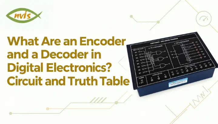
    Encoder and decoder experiments are commonly included in digital-electronics laboratory courses, although the exact experiments vary by institution and curriculum. A dedicated encoder and decoder trainer built specifically for 8 to 3 line encoder and 3 to 8 line decoder verification lets students confirm every row of truth table directly, using SPDT switches for inputs and LED indicators for outputs, without needing to wire discrete gates from scratch for every experiment. Such trainers can simplify laboratory experiments by reducing the amount of discrete wiring required and making it easier for students to observe the input-output relationship.

    For students without lab access, simulation tools such as CircuitVerse and Virtual Labs initiative from Indian institutes of technology offer the same experiment online, and are a reasonable substitute for building intuition before an exam or a practical lab.

    Why Do Encoders and Decoders Matter for GATE, SSC JE, and RRB JE?

    In the GATE 2026 Electronics and Communication Engineering syllabus, Digital Circuits includes combinational circuits, Boolean minimization, logic gates, arithmetic circuits, code converters, multiplexers, and decoders. Encoders are not explicitly named in the syllabus, although encoder-related concepts can fall within the broader combinational-circuit and code-converter topics. Decoders and multiplexers are explicitly listed in the GATE 2026 ECE Digital Circuits syllabus. Encoders are not explicitly named in the syllabus, although they are closely related to combinational logic and code-conversion concepts. The GATE 2026 ECE syllabus also includes a separate Computer Organization subsection within Section 5, Digital Circuits, alongside combinational and sequential circuits. This does not change the fact that encoders and decoders are primarily studied through combinational-logic concepts.

    SSC JE and RRB JE technical papers for Electronics and Electrical disciplines cover digital electronics as a core subject, and encoder and decoder questions appear both as direct truth table or Boolean expression numericals and as conceptual multiple choice questions distinguishing encoders from decoders or simple encoders from priority encoders. These two circuits are also a near guaranteed topic in PSU technical interviews and viva examinations for electronics and instrumentation roles, since interviewers frequently use them as a quick, low effort way to check whether a candidate genuinely understands combinational logic design rather than having memorized answers.

    Because exact weightage varies by cycle and by paper, students preparing for a specific exam should verify current year’s official syllabus PDF and previous year question paper pattern for their exact discipline (ECE, EE, or Instrumentation) rather than relying on a fixed percentage figure.

    What Career Opportunities Open Up With Strong Digital Logic Skills?

    A solid grasp of combinational logic design, including encoders, decoders, multiplexers, and code converters, is foundational for roles in embedded systems design, VLSI and digital IC design, communication systems engineering, and instrumentation, all of which are active recruitment areas across Indian PSUs and private sector electronics companies.

    Public-sector organisations such as BEL, BHEL, HAL, NTPC, and Power Grid recruit engineers through different routes depending on the organisation, role, and recruitment cycle. Candidates should check each organisation’s current official notification before relying on a particular qualification or selection route. Digital-logic fundamentals are relevant to areas such as embedded systems, FPGA/VLSI design, instrumentation, and digital communication. The importance of specific skills varies by role and organization, though specific salary figures for ISRO and DRDO recruitment were not independently verifiable at time of writing and should be checked against each organization’s own recruitment notification.

    Encoder vs Decoder Difference?

    AspectEncoderDecoder
    Basic functionConverts many input lines into a smaller binary codeConverts a binary code into one active output line
    Typical configuration8 to 3 (octal to binary), 4 to 22 to 4, 3 to 8 (74138), 4 to 16
    Key limitationAmbiguous output if more than one input is active without a priority schemeNone inherent, though enable logic is needed to gate outputs
    Common IC example74148 (8 to 3 priority encoder)74138 (3 to 8 decoder), 7447 (BCD to 7 segment)
    Typical applicationKeyboard encoding, interrupt priority handlingMemory address decoding, chip select generation, display driving
    Related circuitPriority encoder (adds rank to inputs)Demultiplexer (adds a data input to route signals)

    How Should You Move Forward With Encoders and Decoders?

    Encoders and decoders are two sides of the same combinational logic idea: one compresses multiple signals into a compact binary code, and another expands a binary code back into a single active output. A basic encoder works only when inputs arrive one at a time, which is why real systems almost always use priority encoders like 74148 to resolve simultaneous inputs by rank. Decoders like 74138 rely on enable logic and, in most practical ICs, active low outputs to do reverse jobs cleanly, whether that job is selecting a memory chip or driving a display.

    Both circuits are directly testable through Boolean derivation, truth table completion, and priority resolution numericals of the kind shown in worked examples above, which makes them useful topics to understand when preparing for digital-logic questions in technical examinations. The fastest way to make this knowledge permanent is to build circuits, verify every row of truth table by hand or on a trainer kit, and only then move on to multiplexers and demultiplexers, which extend the same core logic with an added data routing dimension.

    FAQs

    What is the main difference between an encoder and a decoder in digital electronics?

    An encoder converts multiple input lines into a smaller binary code, while a decoder converts a binary code into a single active output line among several. They perform inverse operations on each other.

    A simple encoder assumes only one input is active at a time. If two or more inputs go high together, its output becomes ambiguous. A priority encoder assigns a rank to each input and always outputs code for highest priority active input, removing that ambiguity.

    Enable pins allow the decoder to be switched on or off by an external control signal. When the enable condition is not satisfied, every output remains inactive regardless of address inputs, which is essential for building larger memory address maps from multiple decoder chips.

    Decoders and multiplexers are explicitly listed in the GATE 2026 ECE Digital Circuits syllabus. Encoders are not explicitly named, so encoder-related questions should be understood in the context of broader combinational-circuit, Boolean-logic, and code-converter concepts.

    A decoder activates one output line based on a binary select code. A demultiplexer does the same selection but also routes an external data signal to the selected output. Some decoder ICs, including the 74138, can be configured to perform demultiplexing functions by using their enable inputs appropriately.

    74148 is standard TTL 8 to 3 priority encoder, and 74138 is standard TTL 3 to 8 line decoder. Both are widely used in digital electronics labs and referenced in most combinational circuit designs at undergraduate level.
    Tags: encoder and decoder in digital electronics

    What Is Digital Electronics? Basics, Key Concepts and Practical Learning

    TL;DR

    1. This blog is designed for students of engineering, diploma and GATE/SSC JE / RRB JE aspirants who are looking for a good foundation of digital electronics from number systems to logic gates, from combinational to sequential circuits, from counters to the basics of memory.
    2. In digital electronics, the signal is represented as a discrete binary signal (0 and 1), whereas in analog electronics, the signal is represented as a continuous signal. This distinction affects how digital circuits are designed and analyzed.
    3. Digital circuits are broadly classified into two categories: combinational circuits and sequential circuits. Combinational circuits depend on current inputs, while sequential circuits also depend on the circuit’s previous state.
    4. Synchronous and asynchronous design are important topics in digital electronics, particularly when studying counters. Counters are commonly built using flip-flops, with synchronous and asynchronous counters differing mainly in how their flip-flops receive clock signals.
    5. Theoretical knowledge becomes easier to apply through hands-on practice with logic-gate ICs, breadboards, or trainer kits. This practice can also help students explain circuit operation and design decisions more confidently in practical assessments and technical interviews.

    Digital electronics is the branch of electronics concerned with circuits and systems that process information using discrete signal levels, typically represented as binary 0 and 1. It is the basis of all computers and digital devices in use today, such as calculators, computers, communication systems, or industrial controllers. At its core, digital electronics involves using electronic circuits to implement logic, arithmetic, data storage, and decision-making functions.

    This is an even more important topic today than 10 years ago. Digital signals can be stored, processed, copied, and regenerated reliably, with less accumulated degradation from noise than many analog systems, which is why many modern systems, including telecommunications, television, audio, and instrumentation, use digital processing alongside or instead of traditional analog processing.Digital electronics is a fundamental subject for Electronics, Electrical, and Computer Science students and is also relevant to the digital-logic portions of several technical examinations, including GATE and other engineering recruitment examinations.

    This blog will discuss what digital electronics is, the building blocks you need before you move on to circuit design, how logic gates and Boolean algebra work, how to learn the material hands on and how it can be applied to earn marks in the examination and to land you a job.

    Also Read,

    What Fundamentals Do You Need Before Digital Electronics?

    Before studying digital circuits in depth, it helps to understand three fundamentals: number systems and binary representation, binary arithmetic, and voltage levels and logic thresholds.

    A number system is a collection of symbols that can be used to represent quantities. We use 10 digits in our decimal system for everyday use (0 to 9). Digital circuits, on the other hand, are constructed by electronic switches that can be most conveniently designed with only two stable states: on and off. This makes a binary number system, with just two digits (0 and 1), the natural language of digital electronics.

    In addition to binary you will also encounter other number systems such as octal (base 8) and hexadecimal (base 16). These are provided essentially for ease of use. For example, in hexadecimal, engineers can use a single character to represent a 4-bit binary group, allowing machine code and memory addresses to still be easily understood. Converting between these systems, and performing binary arithmetic (addition, subtraction, and two’s complement operations) is prerequisite knowledge and usually covered by most textbooks and question papers prior to introducing gates and circuits.

    The second requirement is knowledge of voltage levels and logic thresholds. A voltage in a digital circuit that is close to the supply voltage is defined as logic 1 (HIGH) and a voltage close to 0 V is defined as logic 0 (LOW). Whether it’s TTL or CMOS, the logic family you are using, the threshold is specific to your logic family, but the concept of a continuous voltage being one of two distinct states is what makes digital electronics different from analog design.

    What Is Digital Electronics, Exactly?

    Digital electronics is the design and analysis of circuits that manipulate, store and communicate information in digital form (as distinct bits and not continuous signals). Most digital circuits can be understood as combinations of logic elements that process binary information according to defined rules.

    The main benefit of this is noise immunity. The analog signal fades over a wire or when it is amplified and it is hard to reverse the fade. Because digital receivers distinguish between defined logic levels, digital signals can often be regenerated and processed with less accumulated degradation than analog signals. However, digital systems can still experience errors, especially when noise exceeds the available noise margins.

    Digital electronics also allows complex logic to be easily handled. While a system with a thousand inputs and outputs would be close to impossible to design reliably with continuously variable signals, the same system designed using binary logic gates can be analyzed, simulated and verified using the mathematical formalism known as Boolean algebra, which has been developed especially for two valued logic.

    How Do Logic Gates and Boolean Algebra Work?

    Physical components that implement logical operations in digital electronics are known as logic gates. The three basic logic gates are AND, OR, and NOT. These gates can be combined to implement other logic functions and, in principle, any Boolean function.

    An AND gate will generate a result of 1 only if all the inputs are 1. The OR gate will output 1 if either or both of the two inputs are 1. A NOT gate – inverter – just switches its single input. These can be combined to get derived gates: NAND (AND followed by NOT), NOR (OR followed by NOT), XOR (output is 1 when only one of the inputs is 1), and XNOR (output is 1 when both the inputs are 1). NAND and NOR are called universal gates because either type can be used alone to implement any Boolean function. This makes them important building blocks in digital logic design.

    These gates combine according to the mathematical system of Boolean algebra. The same operators (AND means multiplication, OR means addition, NOT means complement) are used but there are other laws that are applied such as commutative, associative and distributive laws, and De Morgan’s theorems. The following two theorems are very useful in practice: The complement of OR is equal to AND of complements, and the complement of AND is equal to OR of complements. This allows engineers to use one type of gate to construct a circuit and convert it into another type of circuit when some types of gates are only available on a chip.

    As a Boolean expression gets longer and more complicated, engineers use Karnaugh maps (K maps) for expressions with up to five or six variables, or algorithmically solve larger expressions by using the Quine McCluskey method. Boolean simplification has practical benefits in circuit design. Reducing unnecessary logic can reduce area and, depending on the implementation, may also reduce power, delay, and design complexity.

    What Are Combinational and Sequential Circuits?

    Digital circuits are broadly classified as combinational or sequential, and understanding the difference between them is essential for understanding how counters work.

    Combinational Circuits

    A combinational circuit’s output depends only on its current inputs. There is no memory involved. Half adders, full adders, multiplexers, demultiplexers, encoders, and decoders all fall into this category. Feed the same inputs into a combinational circuit at any time, and you get the same output every time, because the circuit has no way of remembering what happened before.

    Sequential Circuits

    A sequential circuit’s output is not only dependent on the current input but also on the previous state, thus a sequential circuit must have memory. Flip flops are basic storage devices in digital electronics and there are four types to note, SR flip flop (set reset), D flip flop (data or delay), JK flip flop (a modification of SR that does not have an invalid state), and T flip flop (toggle).

    An edge-triggered flip-flop changes its stored state in response to a specified clock edge, typically the rising or falling edge. The clock driven behaviour is what enables sequential circuits to count, store sequences and coordinate the timing of an entire digital system, from a simple digital clock to the internal registers of a microprocessor.

    What Are Counters in Digital Electronics?

    A counter in digital electronics is a sequential circuit, built from a chain of flip flops, that progresses through a fixed sequence of binary states in response to clock pulses. Counters are important sequential circuits used in timers, frequency dividers, digital clocks, event counters, and control logic, frequency dividers, digital clocks, event counters, and control logic of almost every digital system.

    Counters are classified primarily by how their flip flops receive clock signals.

    Asynchronous (Ripple) Counters

    In an asynchronous counter, only the first flip flop receives an external clock pulse. Every subsequent flip flop is triggered by the output of the flip flop before it. This creates a ripple effect, where count change propagates through a chain of flip flops one at a time rather than all at once. Asynchronous counters are simple to build and need fewer gates, but propagation delay accumulates across stages, which limits how fast circuits can reliably count as the number of bits increases.

    Synchronous Counters

    A synchronous counter is a counter in which all flip-flops receive the same clock signal. Combinational logic determines which flip-flops change state on each clock edge. All flip flops change state synchronously, so ripple counter problems of cumulative delay are avoided and the counter is able to run at a much higher clock speed. Although a synchronous counter generally requires more combinational logic, it can provide faster and more predictable timing than an equivalent ripple counter, making it useful when higher operating speed is required.

    Other Common Counter Types

    Besides being classified as synchronous or asynchronous, counters can also be categorized according to their counting sequence. A decade counter, or MOD-10 counter, cycles through ten states, typically 0 through 9, before returning to its initial state, making it an ideal component to build up decimal digital display units. Up-down counters are able to count both ways based upon an input signal for use as part of positioning systems such as sensors or robots. The ring counter moves an individual active bit along a loop of flip-flops to produce one active output per cycle; it is often employed as part of simple sequential circuits. A Johnson counter, also called a twisted-ring counter, feeds the inverted output of the last flip-flop back to the input of the first. An n-bit Johnson counter typically produces 2n distinct states, compared with n states in a basic ring counter.

    Worked Example: Designing a MOD 6 Synchronous Counter

    A typical digital-design problem is to design a synchronous counter that cycles through a specified number of states and then repeats that counts through a fixed number of states and then resets. Here is step by step process for a MOD 6 synchronous counter using JK flip flops, counting from 000 to 101 (0 to 5 in decimal) before repeating.

    Step 1: Determine number of flip flops. A MOD 6 counter needs enough flip flops to represent 6 distinct states. Since 2² = 4 is insufficient and 2³ = 8 is enough, three flip flops (Q₂ Q₁ Q₀) are required, with two of eight possible states (110 and 111) left unused.

    Step 2: Write state sequence. counter must cycle through: 000 → 001 → 010 → 011 → 100 → 101 → back to 000.

    Step 3: Build an excitation table. For each flip flop, compare its present state to its next state and find required J and K inputs using JK flip flop excitation rules: if state stays at 0, J = 0 and K = X (don’t care); if it goes from 0 to 1, J = 1 and K = X; if it goes from 1 to 0, J = X and K = 1; if it stays at 1, J = X and K = 0. Applying this rule across all six valid transitions gives required J and K values for Q₀, Q₁, and Q₂ at every step.

    Step 4: Simplify using K maps. Plotting each flip flop’s J and K values against present states Q₂Q₁Q₀ on a Karnaugh map, and treating two unused states (110, 111) as don’t care conditions, gives simplified Boolean expressions. Working through map produces:

    One valid set of JK input equations for the six-state sequence 000 → 001 → 010 → 011 → 100 → 101 → 000 is:

    J₀ = K₀ = 1

    J₁ = K₁ = Q₀

    J₂ = Q₁Q₀

    K₂ = 1

    These equations implement the specified transitions for the six valid states. The behavior of the unused states 110 and 111 should also be checked separately when designing a self-correcting counter.

    Step 5: Add reset or recovery logic. Since three flip-flops can represent eight states, a MOD-6 counter must ensure that the sequence returns to 000 after 101. In a synchronous design, the next-state logic can directly make 101 transition to 000. Alternatively, a design can allow the counter to enter an unused state such as 110 and then asynchronously clear it to 000. These approaches should be treated as separate design methods.

    Step 6: Draw final logic diagram. The completed circuit uses three JK flip-flops driven by the same clock, with J and K inputs based on the derived equations. If an asynchronous reset is used, additional logic detects the 110 state and clears the counter to 000.

    The same method of building an excitation table followed by K-map simplification can be applied to many synchronous-counter designs, including MOD-6, MOD-10, and custom-sequence counters. This is a standard approach to synchronous-counter design and is useful when solving similar examination problems.

    Where Is Digital Electronics Used?

    Digital electronics underpins nearly every modern electronic system. Microprocessors and microcontrollers rely primarily on digital logic for computation, control, and data processing, although practical chips can also contain analog and mixed-signal circuitry. Digital signal processing systems are widely used in audio, medical imaging, and telecommunications. Many such systems convert analog signals into digital form so they can be processed using digital algorithms, stored reliably, and transmitted or manipulated efficiently.

    Industrial automation relies on digital logic for programmable logic controllers (PLCs) that sequence machinery on factory floors. Communication systems, from fiber optic networks to 5G infrastructure, encode information digitally because digital signals can be error corrected and regenerated across long distances without accumulating noise. Even everyday consumer appliances, washing machines, microwave ovens, and digital clocks, use counters and simple digital logic for their control sequences.

    How Can You Learn Digital Electronics Practically?

    Reading about logic gates and counters builds conceptual understanding, but digital electronics is ultimately a hands-on subject, and building circuits physically closes gaps that theory alone leaves open, such as understanding propagation delay, glitches, and effect of fan out on a real IC.

    A practical starting point is working with breadboards and standard 74 series or 4000 series ICs to build basic gates, then progressing to flip flops and small counter circuits. Verifying a truth table on paper is useful, but watching an LED sequence change as a real counter circuit clocks through its states makes abstract concepts concrete in a way that simulation alone often does not.

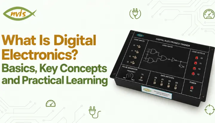
    For structured lab practice, digital IC trainer kits, such as NV6550, a digital IC experimentation platform, let students build and test logic gates, adders, comparators, multiplexers, decoders, flip flops, registers, and counters on same platform using ZIF sockets for quick IC swapping. This kind of structured practice mirrors what a diploma or engineering lab curriculum expects and builds the same design intuition that interview panels test for when they ask candidates to sketch a counter circuit on a whiteboard.

    Circuit simulation software is a useful supplement, particularly for verifying a design before building it physically, but it should not replace physical practice entirely. Physical circuits can expose practical timing and signal-integrity issues, such as propagation delay, setup and hold-time violations, glitches, and loading effects, that idealized simulations may not fully represent.

    Digital Electronics for GATE, SSC JE and RRB JE Exams

    Digital logic is explicitly covered in the GATE syllabus for Computer Science and Information Technology (CS), while digital and logic-circuit topics are also included within the relevant sections of other GATE papers such as Electronics and Communication Engineering (EC) and Electrical Engineering (EE). Check the latest official syllabus for the paper you are taking. GATE syllabi can change between years, so students should always check the official syllabus for their specific paper and examination year. For GATE 2026, Digital Logic is explicitly listed in the CS syllabus, including Boolean algebra, combinational and sequential circuits, minimization, number representations, and computer arithmetic. Digital Electronics is also explicitly listed in the IN syllabus, including sequential circuits, flip-flops, shift registers, timers, and counters.

    For exams such as SSC JE and RRB JE, the depth and type of digital-electronics questions can vary by examination and paper. Candidates should check the latest official syllabus and previous papers for the specific exam and practise identifying gate outputs from truth tables, classifying counters and flip-flops, and solving straightforward numerical problems involving number-system conversions and counter MOD values, classify counters and flip flops, and solve straightforward numerical problems on number system conversions and counter mod values. Digital electronics fundamentals may also be relevant in technical interviews for engineering roles, particularly where the position involves digital logic, embedded systems, VLSI, or hardware design, since interviewers use it to judge how well a candidate understands sequential circuit design rather than just memorized definitions.

    Career and Recruitment Context Where Digital Electronics Skills Take You

    A solid foundation in digital electronics can support career paths in design, testing, embedded systems, VLSI, and other technical areas. Organisations such as ISRO, DRDO, BEL, BHEL, and HAL recruit engineers through different selection processes depending on the role and recruitment cycle, DRDO, BEL, BHEL, HAL, and Power Grid Corporation recruit engineers through different recruitment routes, which can include GATE scores, written examinations, interviews, or organization-specific selection processes depending on the post and recruitment cycle, followed by an interview that routinely covers digital logic fundamentals. If the article is intended primarily as a digital-electronics learning guide, remove the salary detail. If career information is important to the page, move it into a separate, clearly labelled career section and link to the relevant official recruitment notice.

    In the private sector, digital electronics knowledge is foundational for roles in VLSI design, embedded systems, and hardware verification, where semiconductor and product companies test candidates specifically on logic design and sequential circuits during technical interviews. Because this subject sits at the base of so many downstream specializations, from FPGA design to embedded firmware, investing time in genuinely understanding it, rather than memorizing definitions, tends to pay off across multiple career paths rather than just one.

    Digital vs Analog Electronic

    AspectDigital ElectronicsAnalog Electronics
    Signal typeDiscrete (0 and 1)Continuous, varying
    Noise immunityHigh, signal can be regeneratedLow, noise accumulates
    Circuit designBoolean algebra, logic gatesDifferential equations, transfer functions
    PrecisionFixed by bit resolutionLimited by component tolerance
    Common building blocksGates, flip flops, countersAmplifiers, filters, oscillators
    Typical applicationsComputers, digital clocks, communication systemsAudio amplification, sensor signal conditioning, RF front ends

    Digital Electronics Notes Key Points to Remember

    A few facts are worth keeping as quick reference notes, since they come up repeatedly across coursework, notes, and interview questions.

    An n bit binary counter can represent 2ⁿ distinct states, which is why a 3 bit counter naturally counts from 0 to 7 unless additional logic forces an earlier reset, as shown in MOD 6 example above. NAND and NOR are universal gates because either can implement AND, OR, and NOT on its own. De Morgan’s theorems let you convert between AND based and OR based logic expressions, which is essential when a design must use only one gate type. A flip flop is a clocked (edge triggered) storage element, while a latch is a level triggered storage element, and two terms are not interchangeable even though they are often confused. Synchronous counters trade a small increase in gate count for a significant increase in maximum operating speed compared to asynchronous ripple counters.

    Conclusion

    Digital electronics is built on a simple foundation, representing information as discrete binary states, but that foundation supports everything from a basic digital clock to most advanced computing systems in use today. Getting comfortable with number systems, logic gates, Boolean simplification, and the distinction between combinational and sequential circuits provides a foundation for topics such as counters and other sequential-circuit designs.

    Treat counters, and sequential circuit design generally, as a skill to build through worked examples and hands on practice rather than memorized facts, since that is exactly how GATE, SSC JE, RRB JE, and PSU interview panels test it. Pair your notes with a breadboard or a trainer kit, work through a few counter designs by hand using the excitation table and K map method shown above, and revisit the comparison table and quick notes in this blog whenever you need a fast refresher before an exam or interview.

    FAQs

    Is digital electronics hard to learn for beginners?

    Not if you build fundamentals in order. Number systems and logic gates are straightforward once practiced, and each later topic, including flip flops and counters, builds directly on one before it. Skipping ahead to counters without a solid grip on Boolean algebra is usually what makes the subject feel harder than it is.

    Work through number system conversions and counter design problems (like MOD 6 example above) by hand first, using excitation tables and K maps, before checking your answer with a simulator. This builds the same problem solving process examiners expect in GATE, SSC JE, and RRB JE papers.

    Yes, It depends on the GATE paper you are taking. For GATE 2026, Digital Logic is explicitly included in the CS syllabus, while digital-electronics topics also appear in other relevant engineering-paper syllabi. Candidates should check the syllabus for their specific paper.

    A combinational circuit’s output depends only on its current inputs, with no memory involved. A sequential circuit’s output depends on both current inputs and the circuit’s previous state, which requires a memory element like a flip flop.

    In a ripple counter, each flip flop must wait for the previous one to change state before it can change, so propagation delays add up across the chain. A synchronous counter clocks every flip flop at the same instant, so its maximum speed depends on a single flip flop’s delay rather than the sum of all of them.

    Notes help you recall definitions and formulas quickly, but Technical interviews for engineering roles may include questions that ask candidates to sketch a circuit or explain how a counter behaves under specific conditions.Pairing your notes with hands on practice, even basic breadboard work, makes a noticeably stronger impression than notes alone.


    Tags: Digital Electronics

    Request a Callback

    Please enable JavaScript in your browser to complete this form.

    No spam. Just a quick call.

    =