





TL;DR
- This blog is for engineering students, diploma students, and GATE/SSC JE/RRB JE aspirants who need a working understanding of encoders and decoders in digital electronics, not just memorised truth tables.
- An encoder compresses multiple active input lines into a smaller binary code, while a decoder performs the reverse operation by activating one specific output line for a given binary code.
- Simple encoders break down when more than one input is active at once. Priority encoders like 74148 fix this by assigning a rank to each input line.
- Decoders such as the 74138 (3-to-8) are commonly used for memory address decoding and chip-select logic, while BCD-to-seven-segment ICs such as the 7447 are used for display driving.
- Decoders are explicitly listed in the GATE 2026 EC syllabus, while the EE syllabus includes combinatorial and sequential logic circuits, multiplexers, and demultiplexers.
An encoder and a decoder are combinational logic circuits that map information between individual signal lines and binary-coded representations. A basic encoder assumes that only one input line is active at a time and generates the binary code corresponding to that input. A decoder performs the opposite operation, taking a binary code as input and activating exactly one of several output lines that corresponds to that code.
These two circuits sit at the center of how digital systems compress, route, and interpret information. Keypad interfaces, interrupt-handling logic, and memory address-decoding systems can use encoding or decoding principles similar to those demonstrated by basic encoder and decoder circuits. Understanding encoders and decoders in digital electronics is also a prerequisite for multiplexers, demultiplexers, and code converters, all of which build on the same input to output mapping principle.
This article covers how encoders and decoders work at gate level, why plain encoders need a priority mechanism to handle real world inputs, how to read and construct their truth tables, and where these circuits show up in actual hardware and in GATE, SSC JE, and RRB JE exam papers.
Also Read,
- Arduino for Embedded Systems Learning: Setting Up Your First Lab Project
- IoT Microcontroller Projects for Engineering Students: From Sensor to Cloud
- ARM Cortex M Microcontrollers Explained: Architecture for Embedded Engineering Students
What Do You Need to Know Before Learning Encoders and Decoders?
Encoders and decoders belong to a category of digital circuits called combinational logic circuits. In a combinational circuit, output at any instant depends only on the current combination of inputs, with no memory of past inputs. This is different from sequential circuits such as flip flops and counters, where output also depends on the circuit’s previous state.
Three ideas from Boolean algebra and logic design are worth having clear before going further. The first is AND OR NOT gate set, since every encoder and decoder can be built entirely from these three gates. Second is the truth table, a tabular listing of every input combination alongside output it produces. Third is the idea of binary weighting, where a group of bits such as Q2 Q1 Q0 represents a decimal value through positional powers of two, the same way a 3 bit output represents values from 0 to 7.
A related term that comes up constantly in this topic is “line,” as in a 3 to 8 line decoder. A line simply means one physical wire or one bit position in a logic circuit. When a data sheet describes a 3 to 8 line decoder, it means three input wires control which one of eight output wires goes active.
What Is an Encoder in Digital Electronics?
An encoder in digital electronics typically has up to 2n2^n input lines and n output lines, with the assumption that only one input is active at a time., where activating one specific input line produces binary code corresponding to that line’s position. A common example is an 8-to-3 encoder, which converts one of eight active input lines into a 3-bit binary code. A smaller example is a 4-to-2 encoder, which converts one of four active inputs into a 2-bit code.
Consider a simple 4 to 2 encoder with inputs D0, D1, D2, and D3. Only one input is assumed active at a time. The truth table looks like this.
| D3 | D2 | D1 | D0 | Q1 | Q0 |
| 0 | 0 | 0 | 1 | 0 | 0 |
| 0 | 0 | 1 | 0 | 0 | 1 |
| 0 | 1 | 0 | 0 | 1 | 0 |
| 1 | 0 | 0 | 0 | 1 | 1 |
Reading this table, when D1 is active input, the encoder outputs Q1Q0 = 01, which is the binary equivalent of number 1. Each output bit is generated by ORing together input lines that should set that bit high. For this example, Q0 = D1 + D3 and Q1 = D2 + D3, where “+” represents logical OR. A circuit built directly from these two equations, using two OR gates, is the entire encoder.
Why Do Simple Encoders Fail With Multiple Active Inputs?
The truth table above only defines valid outputs when exactly one input line is active. If D1 and D2 are both HIGH at the same time, the OR-based equations produce Q1Q0 = 11, even though no single input corresponds to that condition in the original encoder’s truth table. That output looks identical to what D3 alone would have produced, so a downstream circuit cannot tell whether D3 was pressed or whether D1 and D2 were both pressed together.
This ambiguity is a genuine limitation, not a corner case that can be ignored. Any real system, from a calculator keypad to a set of interrupt request lines from multiple peripherals, has to deal with two or more inputs arriving close together. Priority encoders exist specifically to resolve this problem.
What Is a Priority Encoder and How Does It Solve This Problem?
A priority encoder is an encoder that assigns a fixed rank to each input line and, when multiple inputs are active simultaneously, generates a binary code corresponding to the highest-priority active input while ignoring lower-priority inputs. The 74148 is an 8-to-3 TTL priority encoder with active-low data inputs and active-low outputs. D7 has the highest priority and D0 the lowest.
The table below shows a generic active-high 8-to-3 priority encoder with D7 as the highest-priority input. Note that the 74148 uses active-low inputs and active-low outputs, so its truth table uses the opposite logic convention.
| D7 | D6 | D5 | D4 | D3 | D2 | D1 | D0 | Q2 | Q1 | Q0 |
| 0 | 0 | 0 | 0 | 0 | 0 | 0 | 0 | 0 | 0 | 0 |
| 0 | 0 | 0 | 0 | 0 | 0 | 0 | 1 | 0 | 0 | 0 |
| 0 | 0 | 0 | 0 | 0 | 0 | 1 | X | 0 | 0 | 1 |
| 0 | 0 | 0 | 0 | 0 | 1 | X | X | 0 | 1 | 0 |
| 0 | 0 | 0 | 0 | 1 | X | X | X | 0 | 1 | 1 |
| 0 | 0 | 0 | 1 | X | X | X | X | 1 | 0 | 0 |
| 0 | 0 | 1 | X | X | X | X | X | 1 | 0 | 1 |
| 0 | 1 | X | X | X | X | X | X | 1 | 1 | 0 |
| 1 | X | X | X | X | X | X | X | 1 | 1 | 1 |
Whenever D7 is the highest-priority active input, the encoder outputs 111, regardless of the lower-priority inputs. Only when D7 is 0 does the encoder even look at D6, and so on down the priority chain. Boolean equations for outputs follow directly from this structure. For example, Q2 = D4 + D5 + D6 + D7, since any of these four higher order inputs being active sets the most significant output bit.
Real priority encoder ICs like 74148 add two more features that most introductory explanations skip over. The Enable Input (EI) pin is active low and controls whether the device is enabled. The Group Select (GS) output indicates that at least one valid input is active. Because the 74148 uses active-low logic, these conditions should be interpreted according to the device’s polarity, and it solves exactly ambiguity mentioned earlier: without GS, there is no way to distinguish “D0 is active” from “no input is active,” since both produce Q2Q1Q0 = 000 in a basic priority encoder. The Enable Output (EO) pin supports cascading multiple 74148 devices to build wider priority encoders.
What Is a Decoder in Digital Electronics?
A decoder in digital electronics takes an n-bit binary code and, when enabled, activates the output corresponding to that code while keeping the other outputs inactive., one whose position corresponds to input code. A decoder is, in effect, the structural inverse of an encoder: an encoder maps many lines to one code, and a decoder maps one code back to many lines.
The simplest example is a 2 to 4 decoder with inputs A and B and four outputs, Q0 through Q3. Its truth table is short enough to build from first principles.
| A | B | Q0 | Q1 | Q2 | Q3 |
| 0 | 0 | 1 | 0 | 0 | 0 |
| 0 | 1 | 0 | 1 | 0 | 0 |
| 1 | 0 | 0 | 0 | 1 | 0 |
| 1 | 1 | 0 | 0 | 0 | 1 |
Each output is a minterm of inputs, meaning each output equation is an AND of A, B, or their complements, matched to exactly one input row. Q0 = A’B’, Q1 = A’B, Q2 = AB’, and Q3 = AB, where A’ denotes logical complement (NOT) of A. Building this decoder takes four 2 input AND gates and two inverters, nothing more.
Scaling this idea up gives a 3-to-8-line decoder, a configuration implemented by ICs such as the 74138, one of most widely used decoder chips in digital systems. It takes three input lines and produces eight mutually exclusive outputs, following the same minterm logic as 2 to 4 decoder, just extended to three variables.
Most practical decoder ICs, including 74138, add one or more Enable inputs. When the enable condition is not met, every output stays inactive no matter what input code is. 74138 specifically uses three enable pins, G1 (active high) and G2A and G2B (both active low), and all three must be satisfied simultaneously (G1 = 1, G2A = 0, G2B = 0) before decoder responds to its three address inputs at all. This enable logic is what allows a single decoder to be switched on and off by a larger system, which turns out to be essential for address decoding in memory systems, covered later in this article.
A second practical detail worth knowing: many decoder ICs, including 74138, produce active low outputs rather than active high outputs. This means the selected output line goes to logic 0 while every other output stays at logic 1, the opposite convention from 2 to 4 decoder truth table shown above. This is achieved by implementing a decoder with NAND gates instead of AND gates. underlying logic and truth table structure stay the same; only polarity of active output flips.
How Do You Solve a Priority Encoder Problem Step by Step?
The following worked example follows the style of question commonly seen in GATE, SSC JE, and RRB JE technical papers, where a set of simultaneously active inputs is given and resulting output code has to be determined.
Problem: An 8-to-3 generic active-high priority encoder has inputs D7 through D0, with D7 assigned the highest priority and D0 the lowest. Inputs D1, D4, and D6 are simultaneously HIGH, while all other inputs are LOW.
Step 1: List active inputs. D1 = 1, D4 = 1, D6 = 1. All remaining inputs (D0, D2, D3, D5, D7) are 0.
Step 2: Identify highest priority active input. Priority increases with input number, so among D1, D4, and D6, input D6 has highest priority. D7 is not active, so it is excluded first.
Step 3: Apply priority rule. Because D6 is the highest priority active input, the encoder ignores D1 and D4 entirely. output depends only on D6.
Step 4: Convert winning input’s position to binary. D6 corresponds to decimal 6. In the 3 bit binary, 6 is represented as 110.
Step 5: State result. Q2 Q1 Q0 = 110. If the encoder is a 74148, its Group Select (GS) output is active LOW. Therefore, when at least one valid input is active and the device is enabled, GS goes LOW. This helps distinguish an active input condition from the no-input condition. Without GS, an active D0 condition and the no-input condition can both produce Q2Q1Q0 = 000 in a basic priority encoder.
A second short example applies the same reasoning to a decoder used for memory address decoding, a common follow up question type. Problem: A 74138 3 to 8 decoder has its enable pins correctly satisfied (G1 = 1, G2A = 0, G2B = 0) and its address inputs set to C B A = 1 0 1. Which output line goes active, and at what logic level?
Since C B A = 101 is binary for 5, output Y5 is selected. Because 74138 produces active low outputs, Y5 goes to logic 0 while Y0 through Y4 and Y6, Y7 all remain at logic 1.
Where Are Encoders and Decoders Used in Real Circuits?
Keyboard interfaces are a common example used to explain encoding and priority logic. Keyboard interfaces commonly use matrix scanning to detect key presses efficiently and then generate key or scan codes for processing. Encoder and priority-logic concepts are related to this process, although an actual keyboard controller is more complex than a simple priority encoder.
Interrupt-handling systems can use priority logic based on the same basic principle. Multiple peripherals, a keyboard, a disk controller, a timer, a communication port, can each request processor’s attention by raising an interrupt request line. A priority encoder (or a priority interrupt controller built around the same principle) assigns rank to these requests, so the system can determine which pending request should be serviced first according to the defined priority scheme.
Decoders are just as central to memory systems. In a microprocessor system, address-decoding logic uses address bits to generate chip-select, bank-select, or row-select signals. Depending on the memory architecture, the decoder may select a memory chip, bank, or word line rather than directly selecting an individual memory cell. Address decoding using cascaded 74138 decoders is a standard technique for building larger memory maps out of smaller memory chips.
BCD to seven segment decoders, such as 7447 IC, take a 4 bit binary coded decimal input and drive seven segments of an LED display to show corresponding digit. This is a decoder in the same combinational sense described earlier, just with a truth table designed around segment patterns instead of single line outputs.
Decoders also function as demultiplexers when an additional data input is added: instead of simply activating a line, they route an incoming data signal to one of several destinations based on the same binary select code. This dual role, decoder and demultiplexer built from identical hardware, is why two terms are often mentioned together in data sheets and textbooks.
How Can You Practice Encoder and Decoder Circuits Hands On?
Reading a truth table is not the same as watching one behave in hardware. Building an 8 to 3 encoder or a 3 to 8 decoder on a breadboard, then flipping input switches and watching which output LED lights up, makes priority logic and enable pin behavior concrete in a way that a printed table cannot.
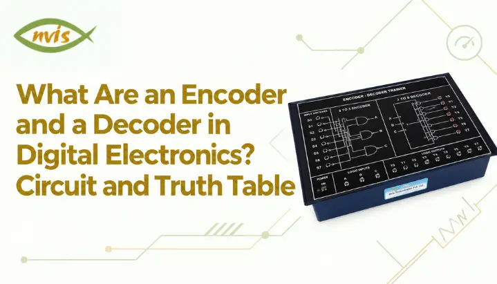
Encoder and decoder experiments are commonly included in digital-electronics laboratory courses, although the exact experiments vary by institution and curriculum. A dedicated encoder and decoder trainer built specifically for 8 to 3 line encoder and 3 to 8 line decoder verification lets students confirm every row of truth table directly, using SPDT switches for inputs and LED indicators for outputs, without needing to wire discrete gates from scratch for every experiment. Such trainers can simplify laboratory experiments by reducing the amount of discrete wiring required and making it easier for students to observe the input-output relationship.
For students without lab access, simulation tools such as CircuitVerse and Virtual Labs initiative from Indian institutes of technology offer the same experiment online, and are a reasonable substitute for building intuition before an exam or a practical lab.
Why Do Encoders and Decoders Matter for GATE, SSC JE, and RRB JE?
In the GATE 2026 Electronics and Communication Engineering syllabus, Digital Circuits includes combinational circuits, Boolean minimization, logic gates, arithmetic circuits, code converters, multiplexers, and decoders. Encoders are not explicitly named in the syllabus, although encoder-related concepts can fall within the broader combinational-circuit and code-converter topics. Decoders and multiplexers are explicitly listed in the GATE 2026 ECE Digital Circuits syllabus. Encoders are not explicitly named in the syllabus, although they are closely related to combinational logic and code-conversion concepts. The GATE 2026 ECE syllabus also includes a separate Computer Organization subsection within Section 5, Digital Circuits, alongside combinational and sequential circuits. This does not change the fact that encoders and decoders are primarily studied through combinational-logic concepts.
SSC JE and RRB JE technical papers for Electronics and Electrical disciplines cover digital electronics as a core subject, and encoder and decoder questions appear both as direct truth table or Boolean expression numericals and as conceptual multiple choice questions distinguishing encoders from decoders or simple encoders from priority encoders. These two circuits are also a near guaranteed topic in PSU technical interviews and viva examinations for electronics and instrumentation roles, since interviewers frequently use them as a quick, low effort way to check whether a candidate genuinely understands combinational logic design rather than having memorized answers.
Because exact weightage varies by cycle and by paper, students preparing for a specific exam should verify current year’s official syllabus PDF and previous year question paper pattern for their exact discipline (ECE, EE, or Instrumentation) rather than relying on a fixed percentage figure.
What Career Opportunities Open Up With Strong Digital Logic Skills?
A solid grasp of combinational logic design, including encoders, decoders, multiplexers, and code converters, is foundational for roles in embedded systems design, VLSI and digital IC design, communication systems engineering, and instrumentation, all of which are active recruitment areas across Indian PSUs and private sector electronics companies.
Public-sector organisations such as BEL, BHEL, HAL, NTPC, and Power Grid recruit engineers through different routes depending on the organisation, role, and recruitment cycle. Candidates should check each organisation’s current official notification before relying on a particular qualification or selection route. Digital-logic fundamentals are relevant to areas such as embedded systems, FPGA/VLSI design, instrumentation, and digital communication. The importance of specific skills varies by role and organization, though specific salary figures for ISRO and DRDO recruitment were not independently verifiable at time of writing and should be checked against each organization’s own recruitment notification.
Encoder vs Decoder Difference?
| Aspect | Encoder | Decoder |
| Basic function | Converts many input lines into a smaller binary code | Converts a binary code into one active output line |
| Typical configuration | 8 to 3 (octal to binary), 4 to 2 | 2 to 4, 3 to 8 (74138), 4 to 16 |
| Key limitation | Ambiguous output if more than one input is active without a priority scheme | None inherent, though enable logic is needed to gate outputs |
| Common IC example | 74148 (8 to 3 priority encoder) | 74138 (3 to 8 decoder), 7447 (BCD to 7 segment) |
| Typical application | Keyboard encoding, interrupt priority handling | Memory address decoding, chip select generation, display driving |
| Related circuit | Priority encoder (adds rank to inputs) | Demultiplexer (adds a data input to route signals) |
How Should You Move Forward With Encoders and Decoders?
Encoders and decoders are two sides of the same combinational logic idea: one compresses multiple signals into a compact binary code, and another expands a binary code back into a single active output. A basic encoder works only when inputs arrive one at a time, which is why real systems almost always use priority encoders like 74148 to resolve simultaneous inputs by rank. Decoders like 74138 rely on enable logic and, in most practical ICs, active low outputs to do reverse jobs cleanly, whether that job is selecting a memory chip or driving a display.
Both circuits are directly testable through Boolean derivation, truth table completion, and priority resolution numericals of the kind shown in worked examples above, which makes them useful topics to understand when preparing for digital-logic questions in technical examinations. The fastest way to make this knowledge permanent is to build circuits, verify every row of truth table by hand or on a trainer kit, and only then move on to multiplexers and demultiplexers, which extend the same core logic with an added data routing dimension.
FAQs
What is the main difference between an encoder and a decoder in digital electronics?
An encoder converts multiple input lines into a smaller binary code, while a decoder converts a binary code into a single active output line among several. They perform inverse operations on each other.
Why is a priority encoder needed instead of a simple encoder?
A simple encoder assumes only one input is active at a time. If two or more inputs go high together, its output becomes ambiguous. A priority encoder assigns a rank to each input and always outputs code for highest priority active input, removing that ambiguity.
What is the function of the enable pin in a decoder like 74138?
Enable pins allow the decoder to be switched on or off by an external control signal. When the enable condition is not satisfied, every output remains inactive regardless of address inputs, which is essential for building larger memory address maps from multiple decoder chips.
Are encoders and decoders part of the GATE syllabus?
Decoders and multiplexers are explicitly listed in the GATE 2026 ECE Digital Circuits syllabus. Encoders are not explicitly named, so encoder-related questions should be understood in the context of broader combinational-circuit, Boolean-logic, and code-converter concepts.
What is the difference between a decoder and a demultiplexer?
A decoder activates one output line based on a binary select code. A demultiplexer does the same selection but also routes an external data signal to the selected output. Some decoder ICs, including the 74138, can be configured to perform demultiplexing functions by using their enable inputs appropriately.
Which IC is commonly used to build an 8 to 3 priority encoder and a 3 to 8 decoder?
74148 is standard TTL 8 to 3 priority encoder, and 74138 is standard TTL 3 to 8 line decoder. Both are widely used in digital electronics labs and referenced in most combinational circuit designs at undergraduate level.