



TL;DR
- This blog is for electronics, electrical, instrumentation, and computer science engineering students, diploma students, and lab instructors who need a concrete list of experiments a digital electronics trainer kit supports, plus a real framework for comparing kits before buying or recommending one.
- A suitable digital electronics trainer kit can support many standard combinational and sequential logic experiments, including logic gates, adders, subtractors, comparators, encoders, decoders, multiplexers, flip-flops, registers, and counters, provided the kit has the required ICs, sockets, inputs, outputs, and clock facilities.
- Most vendor pages either list every possible IC family without saying what each one is used for, or skip the experiment list entirely and jump straight to price, which leaves actual buying decisions unanswered.
- Six key criteria are especially useful when comparing kits: IC family support, ZIF socket capacity and pin range, power supply capability, input and output interface, clock facilities, and experiment coverage against your syllabus.
- If possible, perform a basic logic-gate experiment before buying or evaluating the kit. Confirm that the input switches, IC sockets, power supply, and output indicators work correctly before moving on to more complex experiments.
Also Read,
- Arduino for Embedded Systems Learning: Setting Up Your First Lab Project
- IoT Microcontroller Projects for Engineering Students: From Sensor to Cloud
- ARM Cortex M Microcontrollers Explained: Architecture for Embedded Engineering Students
What Is a Digital Electronics Trainer Kit?
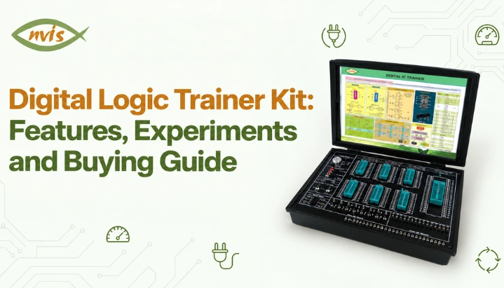
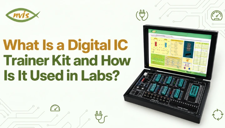
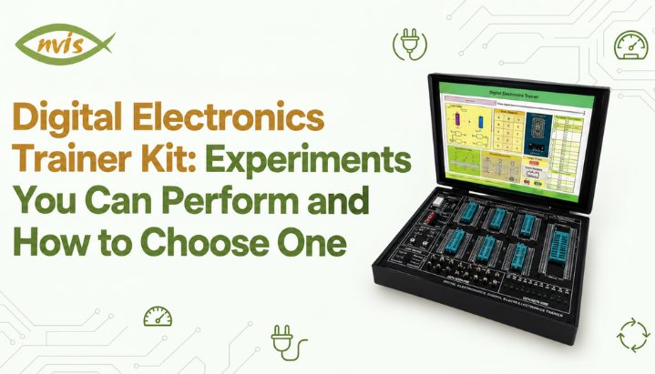
A typical digital electronics trainer kit combines several common subsystems, such as a regulated DC power supply, IC sockets, logic input switches, and LED indicators. Kits designed for sequential-circuit experiments may also include a clock generator and manual pulser that show an output pin’s real voltage state. Many trainer kits designed for sequential-circuit experiments include an onboard clock generator and, in some cases, a manual pulser for generating individual clock pulses.What makes a trainer kit different from a plain breadboard is that all of this supporting circuitry is pre built and pre-wired. A student connects only IC under test and specific patch cords an experiment needs, rather than building a power supply and debouncing switches from scratch before even starting the actual experiment. This is also what makes trainer kit selection a real decision rather than a commodity purchase: two kits that look similar on a vendor page can differ substantially in how many experiments they actually support, once ZIF socket count, IC family compatibility, and clock generator range are compared directly.What Experiments Can You Perform on a Digital Electronics Trainer Kit?
A trainer kit’s ZIF sockets, switches, and indicators are general purpose, so the same board supports a broad set of experiments spanning both combinational and sequential logic, as long as the kit’s socket count and supported IC families match what a given experiment needs. The list below reflects common digital electronics laboratory topics found in engineering and diploma programs in India. Exact experiments vary by university, institution, and syllabus.Combinational Logic Experiments
Combinational experiments produce an output that depends only on current input state, with no clock or memory involved, which makes them a natural starting point on any trainer kit.Verification of basic logic gates, AND, OR, NOT, NAND, NOR, XOR, and XNOR, using ICs such as 7408, 7432, 7404, 7400, 7402, 7486, and XNOR implemented by combining a 7486 XOR gate with an inverter, such as one gate from a 7404, .is a foundational experiment that many digital electronics trainer kits can support when the required ICs, sockets, inputs, and indicators are available.Half adder and full adder verification uses sum and carry expressions Sum = A ⊕ B and Carry = AB for a half adder, extended to Sum = A ⊕ B ⊕ Cin and Carry out = AB + BCin + ACin for a full adder, typically built from discrete XOR, AND, and OR gate ICs first, then verified using a 4-bit binary adder IC such as the 7483, which performs addition on two 4-bit inputs and provides a 4-bit sum with carry output.Half subtractor and full subtractor verification follows same pattern using borrow logic instead of carry logic, with Difference = A ⊕ B and Borrow = A’B for a half subtractor.Magnitude comparator experiments, using an IC such as 7485, verify whether one multi bit binary number is greater than, less than, or equal to another, and cascading two 4 bit comparators to compare 8 bit numbers is a common extension that demonstrates how larger comparison circuits scale.Encoder and decoder experiments cover both directions of code conversion. An encoder converts one active input line among several into a binary code. A priority encoder extends this concept by assigning priority to inputs, allowing it to produce a valid output even when multiple inputs are active. A decoder performs reverse operation, converting a binary code into one active output line among several.Multiplexer experiments can use ICs such as the 74151 (8-to-1 multiplexer), while decoder experiments can use devices such as the 74138 (3-to-8 decoder). Suitable demultiplexer ICs can be used for dedicated demultiplexer experiments. A multiplexer uses select lines to route one of several input signals to a single output. A demultiplexer performs the reverse operation by routing one input signal to one of several output lines, depending on the select inputs. Multiplexers can also be used to implement Boolean functions directly from their truth tables, reducing the need for separate logic gates.BCD-to-seven-segment decoder experiments use an IC such as the 7447 to convert a 4-bit BCD input into the signals required to display decimal digits on a seven-segment display. The 7447 is designed for compatible common-anode displays, so the display type and driver connections must match. This experiment is a common use of a trainer kit’s built-in seven-segment display, if available.Sequential Logic Experiments
Sequential experiments depend on previous circuit states and, for clocked designs, require a suitable clock source. A trainer kit’s clock generator or manual pulser can therefore be important for experiments involving flip-flops, counters, and shift registers.Flip-flop experiments can cover SR, D, JK, and T types, depending on the ICs available on the trainer kit. Common examples include the 7474 for D flip-flops and the 7476 family for JK flip-flops. SR and T flip-flop behaviour can be studied using suitable ICs or implemented using other available logic elements. Each type’s truth table is verified by setting data inputs, applying a single clock pulse using a manual pulser, and reading output on the LED indicator, then comparing the result against the flip flop’s characteristic equation. NvisTech’s guide to flip flop types and working covers SR, D, JK, and T characteristic equations and master slave configuration that prevents JK flip flop’s race around condition, which is worth reading before this experiment if the underlying theory is not already solid.Shift-register experiments can use ICs such as the 74164 for serial-in, parallel-out operation or the 74195 for shift and parallel-load operations. Depending on the IC available, the laboratory may cover serial-in/serial-out, serial-in/parallel-out, parallel-in/serial-out, and parallel-in/parallel-out configurations.Counter experiments split into ripple (asynchronous) and synchronous designs. A ripple counter is built using cascaded T or JK flip-flops, with each stage clocked by the output of the previous stage. It is relatively simple to wire, but propagation delays accumulate through the chain, limiting its maximum reliable operating frequency. A synchronous counter uses the same clock signal for all flip-flops, avoiding the sequential clocking delay associated with ripple counters and making its timing behaviour more predictable. Mod-N counters can be implemented using either asynchronous or synchronous designs, depending on the required circuit and syllabus. In a design exercise, a synchronous Mod-N counter may require deriving flip-flop excitation equations from a state table.Ring counter and Johnson counter experiments use shift registers with feedback. A ring counter circulates a single 1 through the register, while a Johnson counter feeds the complemented output of the last stage back to the first stage and produces a sequence of states using twice as many states as the number of flip-flops, and both are common variations once basic shift register experiment is complete.How Many of These Experiments Can One Kit Actually Cover?
A suitably equipped trainer kit can cover most or all of the listed combinational and sequential experiments, but the exact coverage depends on its supported ICs, socket capacity, inputs, outputs, and clock facilities, since many individual experiments can be built with one or a few standard ICs and patch-cord connections. The practical limit usually becomes noticeable in multi-IC projects that require several ICs to be wired simultaneously, such as a complete digital clock built from cascaded counter and decoder ICs, where number of available sockets, rather than kit’s experiment coverage in principle, becomes constraint.Worked Example: Study of Logic Gates Experiment
Every other experiment on the list above eventually depends on gate level logic working correctly, which is why study of logic gates experiment is usually first assigned on any trainer kit, and why it is worth working through in complete detail here rather than assuming it is too basic to need explanation.Objective: Verify truth tables of seven basic logic gates, AND, OR, NOT, NAND, NOR, XOR, and XNOR, using standard 74 series ICs on a digital electronics trainer kit.ICs required: 7408 (quad 2 input AND), 7432 (quad 2 input OR), 7404 (hex inverter, for NOT), 7400 (quad 2 input NAND), 7402 (quad 2 input NOR), 7486 (quad 2 input XOR). An XNOR truth table is verified either using a dedicated XNOR IC where kit stocks one, or by inverting the output of a 7486 XOR gate using one gate from a 7404.Procedure:Switch off the trainer kit before inserting the IC. Insert the 7408 AND gate IC into the appropriate ZIF socket and close the socket lever. Identify the VCC and GND pins using the datasheet for the exact IC being used. Connect these pins to the trainer kit’s appropriate supply and ground terminals, ensuring that the IC is correctly oriented.Wire two input pins of gate 1 on IC (typically pins 1 and 2) to two logic switches, and wire output pin (pin 3) to an LED indicator, following the trainer kit’s indicator polarity. Set both switches to logic 0 and record the observed output state, then repeat for remaining three input combinations (0,1), (1,0), and (1,1), recording LED state after each change.Compare four recorded outputs against the AND gate truth table below. An AND gate output is logic 1 only when both inputs are logic 1, and logic 0 for every other combination.| A | B | Y = A AND B |
| 0 | 0 | 0 |
| 0 | 1 | 0 |
| 1 | 0 | 0 |
| 1 | 1 | 1 |
| A | B | OR | NAND | NOR | XOR | XNOR |
| 0 | 0 | 0 | 1 | 1 | 0 | 1 |
| 0 | 1 | 1 | 1 | 0 | 1 | 0 |
| 1 | 0 | 1 | 1 | 0 | 1 | 0 |
| 1 | 1 | 1 | 0 | 0 | 0 | 1 |
How Do You Choose a Digital Electronics Trainer Kit?
Most vendor product pages either list every IC family board it claims to support without saying what experiments that actually enables, or state a price range with no comparable specification behind it. Neither answers the actual buying question, which is whether a specific kit covers everything a specific syllabus or project list requires. Six specifications, compared directly across candidate kits, answer that question.IC family support. Confirm whether it supports 74 series TTL, 40 series CMOS, or both, since this determines which specific ICs from experiment list above can be plugged in directly. A kit built only for one family limits which of standard experiments can be run without external adapter circuitry, and a lab covering a TTL versus CMOS comparison experiment specifically needs a kit supporting both.ZIF socket count and pin range. Count how many ICs it can hold inserted simultaneously, and confirm that the available sockets accommodate the DIP package sizes and pin counts required by the ICs in your experiment list, typically 14 pin and 16 pin for most gate, flip flop, and small counter ICs, and sometimes 20 pin or 24 pin for larger multiplexer or register ICs. A kit with only two or three sockets is workable for single IC gate and flip flop experiments but becomes a bottleneck for a multi IC project such as a digital clock, where several counter and decoder ICs need to be wired and tested together.Power supply rating and stability. Confirm that the onboard regulated supply meets the voltage requirements of the specific IC family used in the experiments. Many classic 74-series TTL devices operate from a nominal 5 V supply, but the allowable range depends on the specific device and family, while the allowable supply range for 4000-series CMOS devices depends on the specific device and manufacturer, so the relevant datasheet should be checked. An unregulated or poorly filtered supply is one of most common causes of an IC behaving unpredictably during an experiment, and this is a specification worth verifying against datasheet rather than trusting a vendor’s general claim of “regulated supply.”Input and output interface. Check the number of logic switches and LED indicators against the number of inputs and outputs required by the experiments you plan to perform, since an experiment involving an 8 input multiplexer or a 4 bit magnitude comparator needs correspondingly more switches and indicators available simultaneously than a basic two input gate experiment does. Some kits also include a seven segment display output built in, which matters directly for BCD to seven segment decoder experiment and saves wiring a separate display module.Clock source. Confirm kit includes both a continuous clock generator, ideally with an adjustable frequency rather than a single fixed rate, and a manual pulser button producing one clean pulse per press. A manual pulser specifically is what makes flip flop, counter, and shift register experiments observable one state change at a time; a kit with only a fast fixed frequency clock and no manual pulse option makes sequential circuit verification considerably harder to read on LED indicators alone.Experiment coverage against your actual syllabus or project list. This is specification vendor pages answer least directly, and it is one worth checking last, after first five are confirmed, by matching a kit’s supported IC list against specific experiments a syllabus or project plan requires, rather than assuming a kit that “supports digital IC experiments” in general covers every specific one needed.Build quality and accessory details matter but are secondary to six specifications above: patch cord quality and quantity, whether a printed or digital IC pinout reference is included, and warranty or replacement terms for a shared lab kit that will see heavy use across multiple student batches each semester.Basic vs Advanced Trainer Kit
| Specification | Basic Kit | Advanced Kit |
| IC family support | TTL only, or CMOS only | Both TTL and CMOS |
| ZIF sockets | 2 to 4, mostly 14/16 pin | 6 or more, spanning 14 pin to 24 pin |
| Power supply | Single fixed 5V rail | Regulated 5V plus a variable CMOS range rail |
| Clock source | Fixed frequency clock only | Adjustable clock plus manual pulser |
| Display output | LED indicators only | LED indicators plus built in seven segment display |
| Experiment coverage | Basic gates, single flip flops, small counters | Full combinational and sequential list, including multi IC projects |
| Typical use case | Individual gate and flip flop verification | Full syllabus lab course and multi IC project work |
What Else Belongs on an Electronics Lab Equipment List Alongside a Trainer Kit?
A trainer kit covers circuit construction, but a complete digital electronics lab equipment list also needs instruments to verify what trainer kit’s LEDs alone cannot fully show: a digital multimeter for checking supply voltage and continuity, a dual trace CRO or digital storage oscilloscope for observing actual signal timing and propagation delay rather than a static high or low reading, a function generator for an adjustable external clock source, and a logic probe for quickly tracing a signal through a circuit without setting up an oscilloscope for every check. NvisTech’s guide to what a digital electronics laboratory should include covers this full equipment list, component inventory, and lab organization in depth, including which specific ICs a lab should stock to match the experiment list above.Do Trainer Kit Experiments Matter for GATE, SSC JE, and RRB JE Preparation?
A trainer kit itself is lab equipment, not an examinable syllabus topic, so no GATE, SSC JE, or RRB JE paper asks a question about a specific kit’s specifications. experiments it supports are a different matter. Logic gate behavior, combinational circuit truth tables, and sequential circuit timing are core topics in GATE Electronics and Communication Engineering (ECE), Electrical Engineering (EE), and Computer Science (CS) syllabi under digital circuits and digital logic, and having actually wired and debugged these circuits on hardware builds a more durable, applicable understanding than memorizing a truth table from a textbook alone.For SSC JE and RRB JE, the relevance of digital logic depends on the specific post and the current examination syllabus. Candidates should check the latest official notification for their recruitment to understand the extent of digital electronics coverage. Practical electronics knowledge may also be useful in technical interviews or assessments for certain engineering roles, depending on the organisation and recruitment process. Candidates may encounter questions about circuit operation, troubleshooting, or projects involving practical electronics. Aspirants should verify current year’s official syllabus notification from SSC and RRB directly before assuming any subject’s exact weightage, since exam patterns are revised periodically.Conclusion
A digital electronics trainer kit’s value comes down to whether it can cleanly reproduce specific experiments a syllabus or a project plan requires, from a basic logic gate truth table through a multi IC counter or shift register design. The combinational and sequential experiment list above covers many topics commonly included in undergraduate digital electronics courses, and six specifications in buying guide, IC family support, ZIF socket count, power supply rating, input and output interface, clock source, and experiment coverage against your actual syllabus, are what separate a kit that handles that full list from one that runs out of sockets or IC support partway through it.most reliable way to confirm a kit is adequate before committing to it is same worked example covered above: wire study of logic gates experiment, verify every truth table exactly, and treat any mismatch as a reason to check kit’s specifications, not just wiring, before moving on to flip flop and counter experiments that depend on same gate level reliability.FAQs
How many experiments can a single digital electronics trainer kit support?
A single well specified trainer kit typically covers full standard combinational list (logic gates, adders, subtractors, comparators, encoders, decoders, multiplexers, BCD to seven segment decoding) and full sequential list (flip flops, shift registers, ripple and synchronous counters), as long as its ZIF socket count and IC family support match what each experiment needs.
What is the first experiment usually performed on a digital electronics trainer kit?
Study of logic gates experiment, verifying truth tables of AND, OR, NOT, NAND, NOR, XOR, and XNOR gates, is almost always the first experiment assigned, since every other experiment on trainer kits depends on gate level logic behaving correctly.
What is the difference between a basic and an advanced digital electronics trainer kit?
A basic kit may provide a fixed-frequency clock or a more limited clock facility, while a more capable kit may provide adjustable clock frequencies and a manual pulse generator, which makes individual gate and flip-flop experiments easier to perform. An advanced kit supports both TTL and CMOS families, offers more sockets across a wider pin range, and includes an adjustable clock plus a manual pulser, which can be particularly useful for a broader range of sequential experiments and multi-IC projects.
Do I need a separate oscilloscope if I already have a trainer kit?
An oscilloscope is not strictly required for every sequential experiment, but it is highly useful when you need to observe clock timing, propagation delay, glitches, or other waveform behaviour that LED indicators cannot show. A trainer kit’s LED indicators show only a static high or low state, while an oscilloscope shows actual waveform, timing relationship to clock, and propagation delay, which are what a student needs to diagnose a timing violation or a race around condition that an LED reading alone cannot reveal.
Which ICs are needed for logic gates experiment specifically?
Standard set is 7408 (AND), 7432 (OR), 7404 (NOT), 7400 (NAND), 7402 (NOR), and 7486 (XOR), with XNOR verified either using a dedicated IC where available or by inverting 7486’s output with one gate from 7404.
Is price a reliable way to compare digital electronics trainer kits?
Not on its own. Price generally tracks ZIF socket count, IC family support, and clock generator quality, but two kits at a similar price point can differ significantly in experiment coverage, so comparing six specifications covered in the buying guide above gives a more reliable comparison than price alone.