TL;DR –
- This blog is written for electronics engineers, technicians, students, educators, and R&D professionals who want a clear, practical understanding of how a digital LCR meter works.
- The blog explains what a digital LCR meter is and why it is essential for accurate measurement of inductance, capacitance, and resistance.
- It breaks down the digital LCR meter working principle, showing how AC signals, phase measurement, and impedance calculation are used.
- The blog covers measurement modes, test frequency importance, and common mistakes to ensure accurate results.
- It highlights real-world applications and advantages of using an LCR meter digital instrument in labs, manufacturing, and education.
Related Blogs
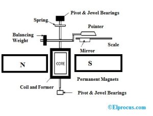
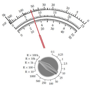
- How Analog and Digital Multimeters Work
- How Practical Labs Make Technical Education and Skilling Industry-Driven
- Why Practical STEM Education Is Essential for Future-Ready Schools
In modern electronics, precision in component measurement is critical. The reliability and performance of a final product is dependent upon the correct knowledge of the precise electrical properties of components, whether you are designing a power supply, debugging a circuit, validating a prototype, or performing quality control on a production line. A digital LCR meter becomes a very crucial tool in this.
In contrast to simple types of multimeters, which simply give approximate values of the resistance, an LCR meter digital instrument is intended to accurately measure the inductance (L), capacitance (C), and resistance (R) under controlled test circumstances. To fully appreciate its value, it is important to understand the digital LCR meter working principle and its step-by-step measurement process.
This article explains the detailed operation of a digital LCR meter. including the signal formation inside a meter and the display of the measurement values in digital form in the end.
What Is a Digital LCR Meter?
A digital LCR meter is a special electronic measuring device used to measure the electrical properties of passive electronic components, like resistors, capacitors and inductors, with high precision. Contrary to the simple multimeters which usually impose DC voltage and can provide only a limited amount of information, digital LCR meter applies a carefully regulated AC test signal and measures how a component behaves under real operating conditions and frequency dependent factors.
The instrument is capable of measuring the electrical properties of a component by measuring the voltage, current, and phase relationship of the current applied as an AC signal. This is particularly handy in a digital LCR meter when accurate and repeatable measurements are important e.g. circuit design, component verification, quality control and research and development.
The three basic parameters that are measured using the instrument are called LCR:
- L – Inductance: The ability of a component, typically a coil, to store energy in a magnetic field when current flows through it.
- C – Capacitance: The ability of a component to store electrical energy in an electric field between conductors separated by an insulating material.
- R – Resistance: The opposition offered by a material or component to the flow of electric current, resulting in energy dissipation as heat.
An LCR meter can give an accurate and understandable reading of the electronic components by digitally processing these values to help engineers, technicians and students of electronic components understand and assess the electronic component.
Why Are Digital LCR Meters Important in Electronics?
Digital LCR meters play a vital role in electronics since they ensure accurate and repeatable measurements of passive components including resistors, capacitors as well as inductors. A digital LCR meter, in comparison to basic multimeters, applies an AC test signal to the component under measurement, providing measurements of component behavior in realistic operating conditions, and leads to more meaningful and accurate values.
Even minor changes in the values of components in circuit design and development can impact on performance, efficiency and stability. A digital instrument of an LCR meter assists the engineer in checking the real component parameters and tolerance and to comprehend parasitic effects which might affect high-frequency or delicate circuits. The accuracy is needed especially in research, prototyping and validation phases.
Digital LCR meters have also found a wide range of applications in manufacturing and quality control. They enable rapid and reproducible testing to assure component uniformity, screen defects and preserve quality of products. The vivid digital display and multi-parameter readings are more advantageous in education and troubleshooting: it is simpler to examine elements and identify problems related to the circuit. All in all, the worth of digital LCR meter working is that it provides reliable data which can be relied upon in order to design and test electronically.
- Test components at specific frequencies
- Detect faulty or degraded parts
- Compare measured values with design specifications
- Ensure consistency in manufacturing
Because of this, digital LCR meters are widely used in R&D laboratories, educational institutions, service centers, and electronics manufacturing facilities.
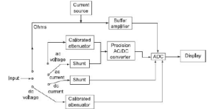
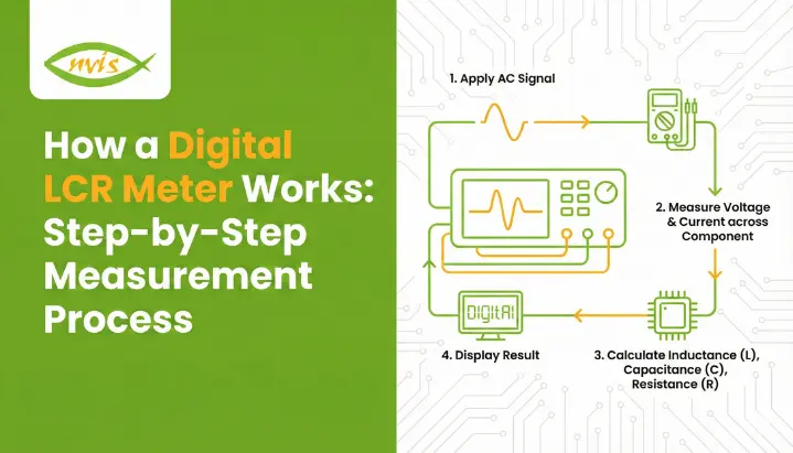
How a Digital LCR Meter Works?
A digital LCR meter is a meter which measures the impedance of a component with a controlled AC test signal instead of a simple DC voltage. This method can give the instrument the chance to test the behavior of a component in the actual operating environment that is important in measuring inductance, capacitance, and resistance accurately.
During operation, the meter sends a given AC signal through a component under test at a given frequency with a given amplitude. It then measures the voltage across the component and the current through the component. The LCR meter digital instrument measures the magnitude and phase difference of a voltage and current to establish the type of response of the component, which is resistive, capacitive, or inductive.
Digital signal processing is used to change the measured values into impedance values and mathematically decompose them into resistance (R), inductance (L), or capacitance (C). The resulting calculated values are then presented precisely on the screen, and in many cases with other values like impedance, phase angle, quality factor or the dissipation factor. This is what makes this digital LCR meter a reliable instrument to test electronics, test a design, or ensure quality control because of a specific and repeatable working process.
Here is a clear, step-by-step explanation of how an LCR meter digital instrument works:
1. Application of AC Test Signal
The digital LCR meter creates an accurate AC signal at a desired frequency and passes it to the component under test. This frequency can also be modified regularly to suit real circuit conditions.
2. Measurement of Voltage and Current
The meter measures the current and voltage across the component in which the signal is passing through as the signal moves through the component. These two values are imperative in calculation of impedance.
3. Phase Angle Detection
The meter identifies the voltage and current phase difference. It is the phase relationship that defines the component as a resistor, capacitor or inductive.
4. Impedance Calculation
Based on the measured value of the voltage, current, and the phase angle, the digital LCR meter then calculates the impedance of the component. Impedance consists of resistive components and reactive components.
5. Extraction of L, C, or R Values
Depending on the impedance measurements and the mode of measurement chosen, the instrument determines values of inductance, capacitance or resistance in a high precision manner.
Step-by-Step Measurement Process of a Digital LCR Meter
Let us now walk through the step-by-step digital LCR meter working process, from component connection to result display.
Step 1: Connecting the Component Under Test (DUT)
The initial one is to couple the component with the LCR meter terminals. Simple measurements can be done with simple test leads. In high precision work with typically low resistance or low inductance parts, Kelvin connections are made to avoid lead resistance errors.
Open-circuit and short-circuit compensation can be carried out before measurement in order to increase accuracy.
Step 2: Applying the AC Test Signal
After connecting the component, a known AC test signal is applied with the help of the digital LCR meter. This signal has:
- A constant frequency or frequency that can be chosen.
- Certain voltage or current level.
Frequency: This is an important decision since different components respond differently to dissimilar frequencies. As a case example, capacitors are frequently tested at 1 kHz, whereas inductors can be tested at lower frequencies.
Step 3: Measuring Voltage and Current
As the AC signal passes through the component, the meter simultaneously measures:
- The voltage across the DUT
- The current flowing through it
These two values form the foundation of impedance calculation.
Step 4: Detecting Phase Difference
One of the most important steps in digital LCR meter working is phase detection. The meter determines the phase angle between voltage and current:
- 0° phase difference: Pure resistance
- Current leads voltage: Capacitive behavior
- Current lags voltage: Inductive behavior
This phase information allows the meter to separate resistance from reactance.
Step 5: Calculating Impedance (Z)
Using the measured voltage (V), current (I), and phase angle (θ), the meter calculates impedance:
Z=VIZ = \frac{V}{I}Z=IV
It then mathematically resolves impedance into its resistive and reactive components.
Measurement Modes in an LCR Meter Digital Instrument
An LCR meter digital meter provides various measurement modes so as to properly represent the electrical characteristics of various components. To get accurate results the mode must be chosen, since real world components have either series or parallel loss characteristics depending upon their value and construction.
Series Mode
A series mode is applied when a component acts as a series combination of both resistance and inductance (R L) or capacitance (R C). This mode is conventionally favored when the losses in series are more important, e.g. small resistors, low-capacitance capacitors, low-inductance coils, etc.
Parallel Mode
Parallel mode can be used when the leakage or dielectric loss characteristics of a device can be modeled in parallel, such as with capacitors and high-value inductances. The component in this mode is modelled to act as a parallel network, which gives more precise results when the component is of high impedance
Auto Mode
At auto mode, the digital LCR meter automatically checks the impedance of the component and automatically chooses either the series mode or parallel mode. This makes measurements easier, besides allowing maximum accuracy without the manual selection of mode.
Importance of Test Frequency in Digital LCR Meter Working
The test frequency is also a key factor in the digital LCR meter functioning, since it directly influences the measurement accuracy and relevance. Passive components do not act perfectly at all frequencies, but rather the electrical behaviour of a passive component varies with frequency of the AC signal applied to it.
- Dielectric losses and parasitic effects usually cause different values of the capacitance of the capacitors at low and high frequencies.
- At lower frequencies, inductors can become core-saturated and at higher frequencies may exhibit resonance effects and change their apparent inductance.
A digital LCR meter provides an option to users to choose the right frequency of the test, which ensures that components are tested under the conditions that are close to their real-life applications. The possibility renders LCR meter digital instrument a necessity to characterize components accurately, design circuits reliably and to be able to control quality.
Applications of Digital LCR Meters
Digital LCR meters have been critical instruments in a broad spectrum of industries since they are precise and flexible in measuring passive components. It is commonly used in:
- Electronics labs Component testing to confirm inductance, capacitance and resistance in circuit design and prototyping.
- During manufacturing, quality assurance whereby the components used are of particular tolerances prior to assembly.
- Failure analysis and repair operations, assisting technicians to locate faulty or damaged parts within a short time.
- Experiments and training in education: students are taught effective methods of measurement and component behavior.
- Development of new circuits, to facilitate accurate testing of the components in controlled test work.
They are critical in the working world because of their capacity to deliver consistent and precise outcomes.
Advantages of Using a Digital LCR Meter
A digital LCR meter has a number of benefits compared to the older component measurement techniques, and it is an essential tool in the electronics testing and analysis of the present day.
- High accuracy and resolution, ensuring reliable measurements in measuring inductance, capacitance and resistance.
- Quick and repeatable measurements, which enhance productivity in the laboratory and manufacturing setup.
- Several parameters in one test, e.g. impedance, ESR, quality factor, and dissipation factor.
- Digital display, with user friendly results that are easy to read with minimum set up requirements.
- Automation and data logging enabled so as to integrate with test systems to allow analysis and record keeping.
These advantages make them better than basic multimeters in testing the components.
Conclusion
The knowledge of the functionality of a digital LCR meter can help in enlightening the reasons as to why it is considered a very imperative tool in testing electronics. With the use of a controlled AC signal, the measurement of voltage, current, and phase difference and the digital processing of the findings, an LCR meter digital meter can provide accurate values of resistance, capacitance, and inductance.
Since the digital LCR meter working process comprises step-by-step signal application up to advanced digital computation, the correctness, repeatability, and application-relevant measurement is ensured. Regardless of whether you are an engineer or a student or a technician, it is imperative to know how to operate a digital LCR meter to build reliable and high-performance electronic systems
FAQs
A digital LCR meter is used to measure inductance, capacitance, and resistance of electronic components with high accuracy. It applies an AC test signal to analyze real operating behavior, making it ideal for labs, manufacturing, R&D, and educational testing.
Unlike a multimeter that mainly uses DC measurement, a digital LCR meter uses AC signals and phase analysis. This allows it to measure L, C, and R accurately at different frequencies, giving more realistic and reliable component values.
Components behave differently at different frequencies. Capacitors change value with frequency, and inductors may resonate or saturate. A digital LCR meter allows frequency selection to ensure measurements match real application conditions.
Series mode is used for low-value components where series losses dominate, while parallel mode suits high-value components with leakage losses. Auto mode selects the best option automatically based on impedance for accurate results.
No, components should be tested outside the circuit. In-circuit measurements can give incorrect readings due to parallel paths and other components affecting impedance, leading to inaccurate LCR values.