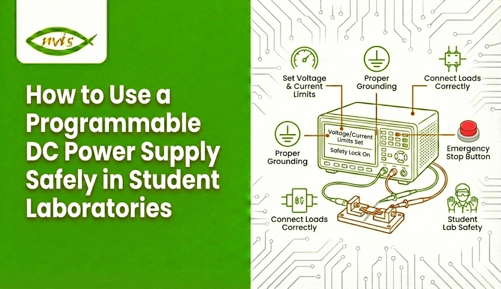
• Nvis Technology
  • Nvis Technology
  • Nvis Technology
  • Nvis Technology
  • Nvis Technology
  • Nvis Technology
Nvis Technology

Head Office

141-A, Electronic complex, Pardesipura,Indore - 452010 India

Phone: +91 73899 00887 , +91 98932 70303

Email:info@nvistech.com

Request a Quote

Looking for a quality and affordable builder for your next project?


    Nvis Technology

    Toll Free

    +91 73899 00887

    We are happy to meet you during our working hours. Please make an appointment.

    • Monday-Saturday: 9:00 AM - 5:30 PM (IST)
    • Sunday: Closed

    Why Antennas Fail Without SWR Measurement: Understanding SWR Meters for Students

    TL;DR –

    • This blog is designed for students of electronics, electrical engineering, RF, and communication systems, helping them understand why antennas fail and how SWR measurement prevents those failures.
    • Antennas often underperform or fail not because of poor design, but due to lack of proper SWR measurement, which leads to power reflection and mismatch issues.
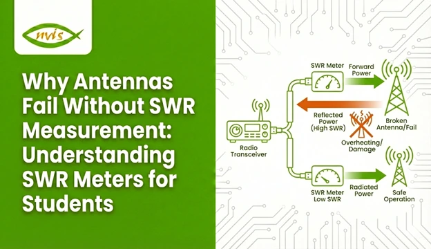
    • An SWR meter measures forward and reflected power to indicate how well an antenna is matched to the transmitter and transmission line.
    • High SWR causes signal loss, inconsistent results, and potential transmitter damage, making experiments unreliable and unsafe.
    • Learning SWR measurement early helps students build strong RF fundamentals, improve antenna tuning, and develop professional troubleshooting and measurement skills.

    Antennas are usually presented to students as simple elements such as metal rods, traces, or wires that transmit and receive signals. Theoretically, they appear simple. Practically, however, one of the most vulnerable components of any RF or wireless system is an antenna. Poor signal strength, limited range, unstable communication, overheated transmitters, or even total system failure are problems students often encounter, even when using a supposedly correct antenna design.In most cases, the cause of the problem is not faulty hardware or incorrect operating frequency. The actual issue is the absence of proper SWR measurement.

    The Standing Wave Ratio (SWR) is a basic RF parameter that is a direct indication of how well an antenna fits its transmission line and transmitter. One of the most frequent and often most costly errors in student laboratories and early engineering projects is ignoring SWR. It is at this point that the SWR meter proves necessary.

    This blog explains why antennas fail without SWR measurement, how an SWR meter works, and why learning SWR measurement early is essential when developing effective and reliable antenna systems.

    Related Blogs

    What Is an SWR Meter?

    The SWR meter is a specialized RF meter that is aimed at measuring the standing wave ratio in a transmission system. It does this by comparing:

    • Forward power (power between transmitter and antenna)
    • Reflected power (power being reflected off the antenna)

    The SWR meter measures and indicates the SWR of the system by examining the ratio of these two numbers.

    An SWR meter is one of the most useful learning tools in RF engineering because it bridges theoretical concepts with real-world measurements.

    Understanding SWR Meters for Students

    The SWR meter is a very significant but frequently misinterpreted device to students who are first entering the field of RF and wireless communication. Although antennas, transmitters and receivers often receive the greatest focus, the SWR meter is a vitally important (often behind-the-scenes) factor that ensures all these elements operate properly and safely to achieve effective coordination.

    In its simplest form an SWR meter is utilized to carry out SWR measurement, which informs us of the suitability of an antenna to the transmission line and transmitter. An excellent match permits the antenna to radiate as much power as possible whereas poor match reflects the power back to the source. These considerations are not observable physically, yet their consequences such as loss of signal, overheating and erratic performance are very noticeable.

    How does an SWR Meter Work?

    An SWR meter is typically inserted inline between the transmitter and the antenna. Inside the meter, directional couplers sample both forward and reflected RF energy.

    The meter then:

    1. Measures forward power
    2. Measures reflected power
    3. Computes the SWR value
    4. Displays the result using an analog scale or digital readout

    This process allows students to instantly see how antenna changes affect system performance.

    Why Antennas Fail Without SWR Measurement

    1. Power Reflection and Signal Loss

    With a high SWR, not much power is transferred into the antenna. The system also dissipates energy in reflections instead of radiating energy. This causes weak signals, reduced range, and unreliable communication—issues that are particularly evident in student projects.

    2. Transmitter Stress and Damage

    Power reflected from the antenna travels back to the transmitter output stage. Even though many modern transmitters include protection circuits, repeated exposure to high SWR can still cause damage.

    • Excessive heat in the output transistor
    • Shortened transmitter lifespan
    • Automatic power reduction or shutdown

    Without SWR measurement, students may unknowingly operate equipment under unsafe conditions.

    3. Inconsistent Experimental Results

    High SWR can bring about unpredictability. Even two similar experiments can yield different results due to the mere fact that the antenna system is unstable. This makes learning frustrating and experimental conclusions unreliable.

    4. Misdiagnosis of Problems

    Students often blame system failures on cables, radios, or software. As a matter of fact, many problems are actually caused by antenna mismatch. The measurement of SWR is fast in detecting the root cause, which is the antenna system.

    How SWR Measurement Improves Antenna Performance

    SWR measurement allows students to:

    • Tune antenna length accurately
    • Optimize antenna placement
    • Detect faulty connectors or damaged cables
    • Validate theoretical antenna designs
    • Achieve consistent, repeatable results

    By adjusting the antenna while monitoring SWR, students gain direct insight into RF behavior—an experience no simulation alone can provide.

    Types of SWR Meters Students Should Know

    Analog SWR Meters

    Analog SWR meters use a printed scale and a moving needle.They are widely used in teaching laboratories because they display SWR behavior graphically and are easy to interpret.

    Digital SWR Meters

    Digital SWR meters have numeric displays, better precision and, in many cases, additional parameters including power level and frequency. They are suited to the more sophisticated labs and more contemporary RF work.

    Integrated SWR Measurement

    A few current radios and RF modules have built-in SWR measurement. Although convenient, standalone SWR meters are more valuable to learn due to the exposure of the measurement process.

    Basic SWR Measurement Procedure for Students

    1. Connect the SWR meter between the transmitter and antenna
    2. Set the transmitter to the desired frequency
    3. Measure forward power
    4. Measure reflected power
    5. Read the SWR value
    6. Adjust the antenna and repeat

    Why Students Should Learn SWR Measurement Early

    Mastering SWR measurement builds:

    • Strong RF fundamentals
    • Measurement discipline
    • Troubleshooting confidence
    • Professional engineering habits

    Engineers who understand SWR stand out because they design systems that work reliably beyond simulations.

    The Educational Value of an SWR Meter

    An SWR meter provides instant cause and effect feedback, unlike many instruments. Learners are able to observe the increase in performance in real time when they tune up an antenna. This is an experience-based learning that speeds the learning process, and reinforces fundamental RF concepts.

    Conclusion: Reliable Antennas Begin with SWR Measurement

    Antennas rarely fail due to theory; they fail due to poor matching and the absence of proper measurement. The measurement of SWR is not optional, it is fundamental. In its absence, antennas perform poorly, transmitters are stressed, and experimental results become unreliable.

    The SWR meter, in addition to being a test instrument, is also a learning companion to all students who deal with RF systems. With knowledge and use of SWR measurement, students no longer work through trial and error but they are practicing real engineering.

    For anyone serious about antennas and wireless communication, learning how to measure SWR is not only advisable but essential.

    FAQs

     SWR (Standing Wave Ratio) shows how well an antenna is matched to the transmitter. A low SWR means power is going to the antenna properly, while a high SWR means power is being reflected back.

      Without SWR measurement, antenna mismatch goes unnoticed. This causes weak signals, poor range, and can even damage the transmitter over time.

    An SWR meter measures forward and reflected power in an RF system and shows how efficiently the antenna is working.

    An SWR close to 1:1 is best. For student projects, an SWR below 2:1 is generally safe and acceptable.

     Yes. An SWR meter helps students tune antennas correctly, avoid equipment damage, and understand real-world RF behavior better than theory alone.

    Tags: SWR Measurement, SWR meter

    What Makes Microwave Power Measurement Easier?

    TL;DR –


    • The blog will target RF engineers, electronics engineers, test and measurement engineers, R&D teams and manufacturing/QA engineers involved in working with microwave and RF systems.
    • Microwave power measurement is critical for system performance, regulatory compliance, and reliability in wireless, aerospace, defense, and industrial applications.
    • The development of sensors, digital meters, and real-time measurement methods has increased the speed of the Power Measurement, making it more accurate and accessible, as compared to the traditional approach.
    • Being automated, remotely controlled, and data logging software eases the workload, minimizes human error, and provides efficiency in the laboratory and production process.
    • Recent Microwave Power measurement products simplify the setup process, minimize errors, and provide repeatable and consistent results in the laboratory, production lines and field testing.


    Precision microwave power measurement is one of the foundations of RF and microwave engineering. In the validation of wireless communication systems and the performance of radar and satellite systems, accurate and efficient Microwave Power Measurement directly impacts product quality, compliance, and system reliability.

    In the past, Power Measurement at microwave frequencies has been deemed complex, time consuming and sensitive to setup errors.. Advancements in sensor technology, instrumentation, software, and automation have transformed this process. As a result, microwave power testing today is faster, more user-friendly, and highly repeatable.


    Also Read:

    Understanding Microwave Power Measurement

    Microwave power is the amount of electromagnetic energy transmitted per unit time at microwave frequencies, which are normally in the range of 300 MHz to 300 GHz. As opposed to low-frequency or DC power, microwave signals are waves propagating through transmission lines, waveguides, and space and thus more difficult to measure accurately.

    Why Is Microwave Power Measurement Critical?

    Precise Power Measurement ensures:

    • RF components meet design specifications
    • Wireless systems comply with regulatory standards
    • Transmitters operate efficiently without distortion
    • Devices perform reliably under real-world conditions

    Errors in Microwave Power Measurement can lead to signal degradation, interference, reduced system efficiency, or even hardware failure.

    Faster and More Accurate Measurement Techniques

    Real-Time Measurement Capability

    High-speed sampling allows engineers to:

    • Capture fast signal changes
    • Measure modulated and pulsed microwave signals
    • Analyze transient power behavior

    This is especially important for modern digital communication systems.

    Temperature Compensation

    Advanced sensors automatically compensate for temperature variations, which makes the Microwave Power reading consistent and repeatable in various conditions.

    Role of Software in Simplifying Power Measurement

    1. Automation and Control
      Power Measurement is made easier with software since one can control instruments remotely, run automated tests, and view data in real-time. This reduces manual intervention, minimizes human error, and significantly improves measurement speed and consistency, particularly in production and high-throughput testing environments particularly in a production and high throughput testing setting.
    2. Data Management and Reporting
      The results of the measurements are automatically recorded with the help of modern microwave power measurement software, and therefore, it is not difficult to create compliance reports, monitor long-term changes in performance, and keep quality documentation. This provides traceability, supports regulatory compliance, and simplifies overall test workflows.

    Minimizing Measurement Errors

    High-quality connectors and accessories play a key role in improving Microwave Power measurement accuracy, Precision connectors, low-loss cables, and high-quality adapters reduce impedance mismatches and signal losses and lead to more stable measurements and better repeatability of test configurations.

    Moreover, current Microwave Power Measurement devices also include built-in automatic error correction that compensates for sensor non-linearity. frequency response variations as well as other environmental effects like temperature changes. Such corrections are greatly built in to improve the accuracy and reliability of measurements in comparison with the past manual methods of measurements.

    Applications Benefiting from Easier Microwave Power Measurement

    Wireless Communications

    Accurate Microwave Power Measurement ensures optimal performance in:

    • Cellular base stations
    • Wi-Fi and 5G equipment
    • IoT and short-range wireless devices

    Aerospace and Defense

    Microwave power data is used in radar systems, satellite communications, and electronic warfare applications to ensure mission-critical reliability in satellite communications and electronic warfare applications.

    Research and Development Laboratories

    Simplified Power Measurement allows engineers and researchers to focus more on innovation and less on test complexity.

    Manufacturing and Quality Control

    Fast, automated measurement systems improve throughput and consistency on production lines, reducing defects and rework.

    Choosing the Right Microwave Power Measurement Solution

    To obtain accurate, repeatable, and efficient test results, it is necessary to select the appropriate Microwave Power Measurement solution. The instruments used must be well matched with the testing requirements at present as well as in the future.

    In the measurement equipment, the following are the important factors that should be taken into account:

    Frequency range and power levels
     Ensure the power sensors and meters support the full frequency spectrum and power levels required by your applications, from low-level signal analysis to high-power transmission testing.

    Measurement speed and accuracy requirements
     Fast measurements are important in modulated or pulsed signal applications and high precision is important in compliance testing, calibration and R & D applications.

    Compatibility with existing test systems
     Choose instruments that integrate easily with your current RF setups, automated test equipment, and communication interfaces to minimize reconfiguration and downtime.

    Software and automation capabilities
    Advanced software enables automated measurements, data logging, remote control and simplification of the reporting processes- which would dramatically enhance productivity and minimize operator error.

    Through appropriate choice of microwave power sensor combinations, meters and software tools, laboratories and production staff are able to ease up the testing processes, cut down on the measurement effort, and attain a high degree of reliability in the results.

    Future Trends in Microwave Power Measurement

    Higher Frequency Support

    As technologies move toward millimeter-wave and terahertz applications, Microwave Power Measurement tools continue to evolve with wider frequency coverage.

    Smarter Automation

    AI-driven test systems will further simplify Power Measurement by automatically optimizing setups and identifying anomalies.

    Compact and Portable Solutions

    Smaller, USB-powered sensors and handheld meters are making accurate Microwave Power testing accessible outside traditional lab environments.

    Conclusion

    The ease with which Microwave Power Measurement can be performed today is not due to one technology- but rather a collection of smarter sensors, sophisticated digital meters, automation software, better calibration techniques as well as user-friendly design.

    These developments have transformed Power Measurement from a complex, expert-driven task into an efficient, automated process, which can be used in the laboratory, on the production floor, and field testing. With the current rise in the development of microwave technologies, measurement will only get much more precise, faster and convenient, so that engineers can not only be sure that the RF and microwave systems demand at the moment can be met, but also that these systems will operate with ease.

    FAQs

     Modern sensors, digital meters, and automation software simplify microwave power measurement by reducing manual setup, correcting errors automatically, and delivering faster, more accurate, and repeatable results.

     Accurate microwave power measurement ensures RF systems meet specifications, comply with standards, and operate efficiently without signal distortion or performance loss.

     Software enables automated measurements, remote control, real-time monitoring, and data logging, reducing human error and improving testing speed and consistency.

    Common errors include cable losses, impedance mismatch, sensor non-linearity, frequency response variation, and temperature changes, which modern instruments automatically correct.

     Microwave power measurement is widely used in wireless communications, aerospace and defense, R&D labs, and manufacturing for testing, validation, and quality control.

    Tags: Microwave Power, Microwave Power Measurement, Power Measurement

    How Automation Labs Prepare Students for Industry Jobs

    TL;DR

    1.  The blog targets engineering students, technical institutions, trainers in industries and education decision-makers seeking to align academic programs with the emerging industrial demands in the field of lab automation and smart manufacturing.
    2. Automation labs, in contrast to the traditional labs, replicate real industrial conditions with the help of high-quality lab automation systems and lab automation software, allowing the students to acquire the real-world, job-oriented experience.
    3.  Automated lab training creates opportunities to work as Automation Engineer, Control Systems Engineer, Robotics Technician, and Process Automation Specialist, all of which are in increasing demand.
    4.  Investment in the contemporary lab automation systems will improve industry relationships, increase the placement rate, research innovation, and institutional reputation in the competitive education world.


    Lab automation systems are at the core of this transformation Manufacturing plants are transforming into smart factories. Accurate robotics and smart surveillance are essential to pharmaceutical businesses. Experimentation that is data-driven is taking place in research institutions. Lab automation is at the core of this transformation.

    As organizations adopt advanced technologies, the demand for professionals skilled in lab automation systems, robotics, control engineering, and intelligent software platforms continues to grow. However, there is a significant gap between what traditional academic laboratories teach and what modern industries expect from graduates.

    In contrast to traditional laboratories where the emphasis is laid on theory and manual processes, automation laboratories mimic the industrial real-life situations. They equip students with practical skills in lab automation software, programmable systems, robotics, and integrated control technologies aligned with industry demands.

    Industry-leading equipment providers such as Nvis support automation training by offering logic analyzers, LCR meters, IC testers, and data acquisition systems that enhance diagnostics and decision-making capabilities. The company also provides customized industrial automation solutions, which incorporate sensors and control systems to streamline processes and optimize productivity.Nvis provides industries with the power to establish operational excellence and growth sustainability through innovation and quality-based solutions.


    Related Articles

    1. Choosing the Right Power Supply for Your Lab: A Beginner’s Guide to Bench, Programmable & Variable Units
    2. How Practical Labs Make Technical Education and Skilling Industry-Driven
    3. Why Your Electrical Training Lab Needs Safety Earthing Training Work Bench Today


    Understanding Lab Automation in Industry Education

    Automation labs are advanced learning environments that bridge the gap between academic theory and real industrial practice. These labs are equipped with integrated lab automation systems that closely replicate modern industrial operations, unlike traditional labs, which primarily involve manual processes and isolated experiments.

    Automation labs replicate real-world production and research environments to provide students with practical exposure to the tools, workflows and technologies that they will experience in their professional settings. This hands-on method greatly enhances readiness to work, and equips students with the ability to operate in a full framework of a lab automation system.

    In a well-equipped automated lab, students develop the ability to:

    • Design and set up automated workflows- Students learn how to map processes, define operational sequences, and develop structured automation logic. This involves knowing about the flow of materials, incorporation of sensors and real-time monitoring in integrated lab automation systems.
    • Program control systems- Students gain practical experience in programming with PLCs, HMIs, and industrial controllers, which would be relevant in using the lab automation systems. They create, debug, and maintain control logic which controls machines and production processes.
    • Use robotics and intelligent equipment – Robots that are frequently used in automation laboratories are robotic arms, conveyors, smart inspection, and collaborative robots. Learners gain experience in configuration, calibration, safety protocols, and motion programming – competencies that are highly demanded in manufacturing and technology-driven sectors.
    • Analyze process data – The current lab automation environment produces large amounts of operational data. Students get to know how to analyze system metrics, identify areas of inefficiency, and implement data-driven approaches to process optimization.
    • Integrate hardware with lab automation software – One of the critical industry competencies is the ability to connect physical equipment and soft platform of advanced lab automation software. Students are trained on how to set up communication protocols, how to manage data acquisition systems and how to provide smooth integration of software applications and hardware components.

    Automation Labs Prepare for Industry Jobs

    Automation laboratories equip students with skills aligned directly with current industry requirements. Using the real systems of lab automation and sophisticated lab automation software, students can obtain practical experience in programming, system integration, robotics, and process monitoring.

    They simulate real industrial conditions, enabling students to design automated workflows, troubleshoot system faults, and optimize performance within a complete automation ecosystem.

    Consequently, graduates come into the workforce with employment-related experience, skills, and competence in solving problems and the self-confidence to make an impact right away in automation-related fields.

    Practical Skills Developed in Automation Labs

    The true strength of automation labs lies in skill development.

    1. Systems Thinking

    Students learn to see automation not as isolated machines but as interconnected ecosystems. This systems-level understanding prepares them for roles involving integration and process optimization.

    2. Technical Programming Proficiency

    Working with lab automation software, students become proficient in:

    • PLC programming
    • HMI design
    • Communication protocols (Modbus, Ethernet/IP, Profibus)
    • Industrial networking

    Employers highly value these practical programming skills.

    3. Troubleshooting and Diagnostics

    Automation systems are complex. Learning to identify and resolve issues is critical.

    Students practice:

    • Debugging control logic
    • Sensor calibration
    • Fault analysis
    • System performance evaluation

    This builds confidence and job readiness.

    4. Project Management and Collaboration

    Automation labs typically use project-based learning models. Students work in teams to design and implement complete automation projects.

    This fosters:

    • Communication skills
    • Documentation practices
    • Time management
    • Cross-disciplinary collaboration

    These soft skills are equally important in industry.

    Career Opportunities After Automation Lab Training

    Graduates trained in automation labs gain practical experience in lab automation systems, robotics, and lab automation software, which will be very competitive in the job market. The practical experience that they get in dealing with real-time industrial systems equips them with a variety of technical jobs, such as:

    • Automation Engineer – Designs, develops, and maintains advanced lab automation systems for manufacturing and research facilities.
    • Control Systems Engineer – Programs and optimizes PLCs, HMIs, and integrated lab automation system architectures.
    • Robotics Technician – Configures, operates, and maintains robotic equipment within automated production environments.
    • Process Automation Specialist – Improves operational efficiency by implementing intelligent lab automation solutions.
    • Manufacturing Systems Engineer – Integrates hardware and lab automation software to streamline smart factory workflows.
    • Quality Control Automation Analyst – Uses automated inspection systems and data analytics to ensure product consistency and compliance.

    Employers highly value candidates with hands-on experience in automated labs because they require minimal onboarding, understand industrial processes, and can adapt quickly to production environments. This hands-on exposure significantly improves employability and long-term career growth.

    The Competitive Advantage of Automation Labs

    Automation-based labs give students a strong advantage in today’s competitive job market by aligning academic training with real industry requirements. Students who acquire hands-on experience with lab automation systems and professional laboratory automation software become more adaptable to the industrial setting because they are already familiarized with the integrated workflows and operations of the system. This practical exposure reduces onboarding time, lowers training costs, and improves productivity from day one. Consequently, those institutions that have an infrastructure of automation system laboratories tend to record higher employability rates, producing more confident, skilled, and job-ready graduates prepared for the dynamic world of lab automation.

    How Educational Institutions Benefit

    Investing in automation labs provides multiple strategic advantages for educational institutions:

    • Stronger Industry Partnerships
      Institutions with advanced lab automation systems are more likely to collaborate with companies for internships, live projects, research initiatives, and campus placements.
    • Enhanced Research & Innovation
      Modern lab automation system infrastructure supports applied research, prototype development, and innovation-driven projects across engineering and technology disciplines.
    • Improved Academic Reputation
      Offering training in industry-grade lab automation software and real-world automation technologies enhances institutional credibility and market positioning.
    • Better Placement Outcomes
      Students trained in hands-on lab automation environments are more job-ready, leading to stronger placement records.
    • Attracting High-Quality Applicants
      A well-equipped automated lab signals future-ready education, drawing ambitious students seeking practical and career-focused learning.

    Conclusion:

    The future of industry is automated, intelligent, and interconnected, and therefore automation labs are a necessity in contemporary education. Conventional learning alone is not sufficient to prepare students for modern workplaces, which are technology-driven. Automation labs can also be used to supplement the theory and practice divide through hands-on experience with lab automation systems and robotics, as well as high-end lab automation software.

    A well-equipped automation lab enables students to design solutions, manage workflows, optimize processes, and adapt to emerging technologies within a complete automation framework. This benefits the students as it provides them with better career opportunities, institutions as it makes them more relevant and industries with the ability to get skilled, job-ready professionals trained in real-world lab automation environments.

    FAQs

    An automation lab is a modern training lab where students learn using real lab automation systems and tools instead of only theory or manual experiments.

    Students learn programming, robotics operation, system integration, troubleshooting, and how to use lab automation software in real-world setups.

    Hands-on experience with a complete lab automation system makes students job-ready and helps them adapt quickly to industry environments.

    Students can become Automation Engineers, Control Engineers, Robotics Technicians, or work in other roles related to lab automation and smart manufacturing.

    Colleges with advanced automation labs improve student placements, build strong industry partnerships, and offer more practical, career-focused education.

    Tags: Actuators & Drives, automated lab, Automation Lab Training, automation labs, Control Systems Engineering, Electrical Automation, Ethernet/IP), Factory Automation, HMI Programming, Industrial Automation Course, Industrial Networking (Modbus, Industrial Robotics Training, Industrial Sensors, Instrumentation & Control, IoT in Manufacturing, lab automation software, lab automation system, lab automation systems, Mechatronics Lab, PLC Panel Wiring, PLC Training, Process Automation, Process Control Systems, Profibus, SCADA Training, Variable Frequency Drive (VFD)

    Precision-Measurement-Training-for-Modern-Instrumentation-Labs

    TL;DR

    1. The blog will be used by students of engineering, technical institutions, lab managers, training providers, and industry professionals in the field of instrumentation, manufacturing, R&D and quality control to learn about the significance of precision measurement training in contemporary labs.
    2. In accurate measurement, repeatability, reliability, and traceability form the foundation of quality assurance, product verification, research accuracy and industrial compliance.
    3. As digital instruments, automation, AI, and Industry 4.0 evolve, professionals are required not only to operate instruments but also to be proficient in calibration, uncertainty analysis, and advanced measurement systems.
    4. Formal precision measurement training reduces costly production errors and prepares professionals for roles such as Calibration Engineer, Instrumentation Engineer, and Metrology Specialist.
    5. The new technological advances such as AI-based measurement systems, IoT-connected instruments, digital twins, and automated calibration demand the use of modern and industry-fit precision measurement programs in order to remain competitive.


    In today’s technological world, innovation is no longer limited by ideas but by accuracy. Whether designing microprocessors, manufacturing aerospace components, calibrating medical equipment, or validating renewable energy systems, precision measurement is the foundation of success.

    Modern instrumentation laboratories are no longer limited to analog meters and manual gauges. They are advanced environments that comprise digital systems, automation, data analytics and globally applicable calibration standards. As production systems evolve toward smart manufacturing, Industry 4.0, and AI-driven operations, the demand for professionals trained in precision measurement has never been higher.

    Precision measurement training involves more than simply learning how to operate instruments. It involves developing competence in measurement science (metrology), understanding uncertainty, calibration principles, traceability and data interpretation with conviction. Colleges investing in formalized precision measurement courses train students and practitioners to work in high-impact careers in instrumentation, quality assurance, research and development, automation and high-technology manufacturing.


    Related Blogs


    Understanding Precision Measurement in Modern Instrumentation Labs

    Precision measurement is the art and technique of having extremely repeatable, trustworthy, and traceable measurements with a minimal amount of uncertainty. In contemporary instrumentation laboratories, it is used to make sure that not only the results are consistent but also scientifically justified and corresponding to accepted standards. Accurate measurement forms the basis of quality assurance, product validation, research integrity, and industry compliance.

    It involves several critical components:

    • Accurate instrument selection – Choosing the appropriate instrument based on required tolerance, range, sensitivity, and application needs.
    • Calibration against standards – Verifying and adjusting instruments using traceable reference standards to maintain accuracy.
    • Statistical validation – Applying statistical methods to confirm repeatability, reproducibility, and overall measurement consistency.
    • Error analysis – Identifying and minimizing systematic and random errors that may affect results.
    • Environmental control – Managing temperature, humidity, vibration, and other external factors that influence measurement performance.
    • Data interpretation – Analyzing, documenting, and reporting measurement results in accordance with industry and regulatory standards.

    Accuracy is often confused with precision, but they are not the same. Accuracy is the term describing the closeness of a measurement to the accepted or true reference value. Precision is the extent or consistency of the repeated measurement in giving the same result. The smallest increment an instrument can detect is referred to as its resolution. These differences are fundamental in ensuring reliability and credibility in the contemporary instrumentation laboratories.

    The Role of Precision Measurement in Modern Instrumentation Labs

    State-of-the-art instrumentation labs support applications such as academic training, industrial calibration, research and development,  product verification, product quality control and prototype testing. Precision measurement has been critical in all these functions as it provides assurance that results obtained are accurate, repeatable, and traceable to known standards.

    Labs cannot ensure reliability or compliance without strong precision measurement capabilities. Failure to make accurate measurements may cause inaccurate research, defective products, and loss of operations. Hence, quality, credibility, and technical excellence of the current instrumentation laboratories is pegged on precision measurement.

    Why Precision Measurement Training Is Essential in Industry

    Traditional lab education primarily focuses on basic instrument handling, but modern industry requires more advanced technical skills. Due to the development of technology, preciseness in measurement training has been considered a necessity to achieve accuracy, reliability and compliance.

    1. Increasing Technological Complexity

    Modern labs use sophisticated equipment such as digital storage oscilloscopes, high-resolution data acquisition systems, PLCs, automated calibration benches, spectrum analyzers, and laser-based measurement systems. These tools require proper training in order to operate them efficiently and draw conclusions about the results.

    2. Growing Demand for Skilled Professionals

    Electronics and other industries, aerospace, renewable energy and defense demand professionals capable of carrying out high precision testing, performing the uncertainty analysis, handling the schedule of calibration, and troubleshooting the instrumentation problems. Precision measurement training enhances technical capability and workability.

    3. Minimizing Costly Errors

    The consequences of measurement errors include rejected batches, product recalls, warranty, and product delays. Formal training mitigates these dangers and provides dependable and steady output.

    Education in precision measurement has become an urgent need of the contemporary instrumentation laboratory and industry-prepared specialists.

    Key Benefits of Precision Measurement Training

    1. Enhanced Technical Competency

    Professionals understand not only how to measure but how to validate measurements scientifically.

    2. Improved Employability

    Roles include:

    • Calibration Engineer
    • Instrumentation Engineer
    • Quality Control Specialist
    • Metrology Technician
    • Test & Measurement Engineer

    3. Reduced Industrial Risk

    Proper training minimizes production defects and improves system reliability.

    4. Strong Foundation for R&D

    Research depends on accurate experimental data. Precision measurement is foundational to innovation.

    Emerging Trends in Precision Measurement

    The field of precision measurement is rapidly evolving as the modern instrumentation laboratories and the industrial processes are redesigned with the new technologies. Training programs should keep up with such developments in order to be relevant and efficient and can equip the professionals with the next generation measurement systems.

    1. AI-Based Measurement Systems

    Measurement platforms are being introduced with artificial intelligence to increase the detection of anomalies, predictive maintenance, and intelligent calibration schedules. AI-powered systems can analyze large datasets, identify patterns, and improve decision-making accuracy.

    2. IoT-Connected Instruments

    IoT-enabled instruments allow real-time remote measurement, centralized data collection, and enhanced system integration. This interconnectedness increases efficiency in operations, promotes preventive maintenance and is able to manage labs more intelligently.

    3. Digital Twins

    Digital twin technology develops virtual models of measurement environments and systems. These models reproduce the real world conditions to test advanced, optimize performance and predictively analyze and do not interfere with the physical operations.

    4. Automated Calibration Systems

    Calibration automation decreases human error, enhances repetitiveness, and improves reliability of the measurements in general. The automated systems also simplify documentation and make sure that the standards of the industry are met.

    Conclusion:

    Accurate measurement is no longer a luxury; it is a necessity in the contemporary engineering and manufacturing fields, automation, as well as research. As industries operate with tighter tolerances, smarter systems, and stricter quality standards, the need for accurate, reliable, and traceable measurements continues to grow. Modern instrumentation laboratories can no longer rely solely on basic tool-handling methods and need to embrace systematic and industry-oriented courses on precision measurements that not only focus on scientific validation and exposure to practical applications, but also calibration skills, uncertainty assessment, and the incorporation of automation. Companies that invest in extensive training on precision measurement develop professionals who are industry ready and in turn add to innovation, efficiency at work and competitiveness at the global scene. As technology advances and automation expands, the demand for professionals trained in precision measurement will continue to grow.

    NVIS Technologies  delivers advanced technical training systems and lab solutions for engineering education and industrial skill development.

    FAQs

     Precision measurement means taking measurements that are consistent, reliable, and very close to the correct value with minimal error.

    It helps students and professionals learn how to use instruments correctly, reduce errors, and ensure accurate results in labs and industries.

     It is used in industries like electronics, automotive, aerospace, renewable energy, manufacturing, and research labs

    Training includes calibration techniques, error analysis, uncertainty calculation, instrument handling, and data interpretation.

     You can work as a calibration engineer, instrumentation engineer, quality control specialist, or metrology technician in various industries.

    Tags: Advanced Measurement Techniques, Industrial Instrumentation Training, Industrial Sensors & Transmitters, Industry 4.0 Instrumentation, Instrumentation & Control Training, Instrumentation Lab Training, Instrumentation Practical Lab, Measurement & Calibration Training, Metrology Training Program, Modern Instrumentation Course, PID Loop Tuning Training, Precision Calibration Course, precision measurement, Precision Measurement Training, Process Control Measurement, Smart Instrumentation Systems

    Loss Calculation and Performance Prediction Using the Swinburne Test

    TL;DR 

    • This blog is designed for electrical engineering students, lab instructors, maintenance engineers, and professionals who want to understand loss calculation and efficiency prediction of DC machines using the Swinburne Test.
    • The Swinburne Test is an indirect, no-load test used primarily for DC shunt and compound machines to determine efficiency without applying mechanical load.
    • The test calculates constant losses (iron, mechanical, field copper) at no-load and uses them to estimate variable losses at different load conditions.
    • By using measured no-load input power and calculated armature copper losses, engineers can predict machine efficiency at any desired load without physically loading the machine.
    • The method is simple, economical, and suitable for large machines, but it does not account for stray load losses, temperature rise, or commutation performance under full-load conditions.


    The Swinburne Test is one of the most widely used indirect methods for determining efficiency and losses in DC machines. The Swinburne Test enables engineers to determine machine efficiency under different load conditions without physically loading the machine. This makes it cost-effective, safe, and highly suitable for laboratory and maintenance settings.

    The Swinburne Test setup is an essential training system widely used in electrical laboratories for practical learning. It is particularly intended to make students and specialists aware of the fundamental principles, working nature, and performance appraisal of DC motors. The Swinburne Test provides the opportunity to determine losses separately and accurately predict the efficiency of the machine at any given load condition without physically loading it.

    The armature and field winding terminals are separately brought out to an easily accessible terminal box located on top of the motor. The training system also offers special terminals to connect an external rheostat and starter to the control panel. This systematic design ensures clear observation, safe operation, and a comprehensive understanding of the experiment.

    Related Blogs

    1. How a Digital LCR Meter Works: Step-by-Step Measurement Process
    2. How Electricity Training Lab Can Become a Part of School-Level Skill Education
    3. Preparing Future Technicians and Engineers for Smart Energy Management

    What is the Swinburne Test?

    The Swinburne Test is an indirect method developed by Sir James Swinburne to evaluate the performance and efficiency of DC shunt and compound machines. Since no mechanical load is applied during the test, it is also known as a no-load test.

    This test is especially useful for large DC machines that cannot be tested under full-load conditions due to power limitations and mechanical constraints. It provides a simple, economical, and convenient way to predict the performance characteristics of a DC machine.

    Principle of the Swinburne Test

    In this test, the DC machine is operated as a motor at its rated voltage and rated speed. The speed is adjusted using a shunt field rheostat to maintain standard operating conditions.

    The main objective of the Swinburne Test is to determine the constant losses of the machine, which include:

    • Iron (core) losses
    • Mechanical losses (friction and windage)

    These losses are calculated from the no-load input power. Once the constant losses are known, the efficiency of the machine can be estimated at any desired load without actually loading the machine.

    Technical Specifications Of Swinburne Test for DC Machine

    DC Machine Specifications

    • Type: DC Shunt Motor
    • Power Rating: 1 HP (Optional variants available in 2 HP and 3 HP)
    • Rated Voltage: 220 V ±10%
    • Rated Speed: 1500 RPM ±5%
    • Insulation Class: Class “B”
    • Loading Arrangement: Mechanical loading system
    • Brake Drum/Pulley: Cast aluminum construction

    Digital Instrumentation

    • DC Voltmeter: 0–300 V range
    • DC Ammeter: 0–5 A (Two units provided)
    • Digital Tachometer: Up to 20,000 RPM

    Optional Accessories

    • DC Power Supply (Model Nvis 725 / Nvis 725A)
      • Suitable for machines rated up to 2 HP and 3 HP respectively

    Loss Calculation and Performance Prediction

    The main goal of the Swinburne Test is loss calculation and performance forecasting. This method enables engineers to determine the internal losses of a DC machine at no-load and estimate its efficiency at any desired load without physically loading it.

    Loss Calculation

    During the Swinburne Test of dc machine, the machine is operated at rated voltage and speed without load. The input power measured under this condition is mainly used to overcome constant losses. These losses include:

    • Iron losses 
    • Mechanical losses 
    • Field copper loss

    The armature copper loss at no load is calculated using the measured no-load voltage, line current, and field current. The constant losses are obtained by the difference between the total no-load input power and the armature copper loss.

    The load current is used to calculate the variable loss, which is primarily the armature copper loss at the given load. Constant losses plus armature copper loss are then added to give total losses at the same load.

    Performance Prediction

    Once the losses are known, the efficiency of the machine can be predicted for different load conditions. For a motor:

    • Input Power = V × I_L
    • Total Losses = Constant Losses + Armature Copper Loss
    • Output Power = Input Power − Total Losses
    • Efficiency = (Output Power / Input Power) × 100

    This method allows the engineers to draw efficiency against load and determine the condition of maximum efficiency. The Swinburne Test is therefore an effective and economical method for assessing the performance characteristics of DC shunt and compound machines without actual loading.

    Scope of Learning

    The learning span will entail studying and analyzing the various forms of losses that take place in a DC machine and how such losses influence the overall performance. By examining the Swinburne Test, the learners identify the constant and variable losses separately and apply the resulting information to compute and estimate the efficiency of the DC machine at different load conditions without actual loading. This strategy assists in coming up with a clear picture of performance assessment, loss computation techniques, and efficiency estimation techniques in DC machines.

    Advantages and Disadvantages of Swinburne Test

    Advantages

    • Appropriate when large DC machines are to be tested, and no actual load is to be applied.
    • Operates under no-load conditions, making it suitable for laboratory use.
    • The level of input power required is very minimal as it only requires power to cover internal losses.
    • Easy setup and less time consuming than direct load tests.
    • Enables efficiency to be estimated at any desired load without physically loading the machine.
    • Little wastage of energy in testing leading to low heat.
    • Applicable to DC shunt and constant flux compound wound machines.

    Disadvantages

    • Iron losses are assumed constant, although they may vary between no-load and full-load conditions due to armature reaction.
    • Fails to test commutation under real load conditions.
    • Full-load temperature rise cannot be accurately determined using this test.
    • Stray load losses are not considered, which can lead to inaccuracies in efficiency estimation.
    • Not suitable for DC series motors, as no-load operation may be hazardous due to dangerously high speeds.

    Conclusion

    The Swinburne Test continues to be one of the most practical and cost-effective methods for determining efficiency and estimating losses in DC shunt machines. This is because, by measuring no-load input power and distinguishing between constant and variable losses, engineers can predict performance at various load conditions without physically loading the machine. This makes it especially valuable for large DC machines where direct loading would be impractical or economically inefficient.

    To electrical engineers and learners, mastering this test gives a good understanding in machine testing, loss analysis and performance prediction.

    FAQs

    The Swinburne Test is an indirect, no-load test used to determine the efficiency and losses of DC shunt and compound machines without applying mechanical load. It calculates constant losses from no-load input power and predicts performance at different load conditions.

    It is called a no-load test because the DC machine operates without any mechanical load during the experiment. The machine runs at rated voltage and speed, and only the internal losses are measured.

    The test primarily determines:

    • Iron losses 
    • Mechanical losses 
    • Field copper loss

    Armature copper loss is then calculated separately to estimate total losses at different load conditions.

    No. The Swinburne Test is suitable mainly for DC shunt and compound machines with relatively constant flux. It is not suitable for DC series motors because operating a series motor at no-load can result in dangerously high speeds.

    The key advantages include:

    • Low power consumption
    • Simple and economical setup
    • Suitable for large machines
    • Ability to predict efficiency at any load without physical loading
    Tags: swinburne test, swinburne test of dc machine

    Performance Optimization Using the Ward Leonard Method of Speed Control

    TL;DR 

    1. This blog is designed for electrical engineers, automation professionals, industrial plant managers, maintenance engineers, and engineering students who want a deep understanding of the Ward Leonard system and its performance optimization capabilities.
    2. The Ward Leonard method of speed control uses a motor-generator set to regulate DC motor speed by precisely controlling armature voltage through generator field excitation.
    3. The Ward Leonard method provides smooth, stepless speed control, high starting torque, wide speed range, excellent speed regulation, and strong dynamic response.
    4. The Ward Leonard system is widely used in heavy-duty applications such as elevators, steel rolling mills, mining equipment, paper mills, and ship propulsion systems.
    5. Although largely replaced by electronic drives, the Ward Leonard method remains important for legacy systems and serves as a foundational concept behind modern motor control technologies.

    Accurate speed regulation has always been the key to industrial productivity. Whether in steel rolling mills, mine hoists, elevators, or heavy cranes, the ability to control motor speed smoothly and accurately directly determines product quality, operational safety, and overall efficiency. The Ward Leonard system, one of the most powerful and reliable electromechanical solutions ever developed, was widely used by engineers long before the advent of solid-state electronics and digital drives.

    The Ward Leonard method of speed control revolutionized industrial motion control by providing a smooth, step-free, and very responsive speed change to DC motors. The Ward Leonard method remains a foundational principle in electrical engineering and a conceptual basis for modern drive systems, even in the age of thyristor converters and variable frequency drives (VFDs).

    This article provides a detailed guide to the principles, working, performance optimization features, applications, benefits, limitations, and current relevance of the Ward Leonard system. For electrical engineers, automation experts, plant managers, and students, this article provides deep technical and practical insight into how the Ward Leonard system optimizes motor performance.


    Related Blogs –

    Understanding the Ward Leonard System

    The Ward Leonard system is an electromechanical speed control system used with DC motors. It regulates the speed of the motor by changing the voltage applied to the motor armature via a motor-generator set.

    Main Components

    A typical Ward Leonard system consists of:

    1. AC Motor (Prime Mover)
    2. DC Generator
    3. DC Motor (Load Motor)
    4. Field Excitation Control Circuit
    5. Control Panel & Feedback Devices

    System Layout

    AC Supply → AC Motor → DC Generator → DC Motor → Mechanical Load

    The AC motor operates at a fixed rate. It drives the DC generator. The output voltage varies by varying the field current in the generator. This variable voltage is supplied to the DC motor, thereby regulating its speed.

    Principle of Ward Leonard Method of Speed Control

    The Ward Leonard method of speed control is based on the principle of using a motor-generator set to provide precise control of a DC motor’s speed. A common Ward Leonard system has a constant-speed AC motor (prime mover) that drives a DC generator. This generator produces controlled DC voltage which is fed into the DC motor which is driving the load.

    The fundamental idea of the Ward Leonard method is to control motor speed by adjusting the generator field current. This adjustment alters the output voltage of the generator that consequently controls the voltage of the load armature. The speed of a DC motor is directly proportional to the armature voltage applied, so a fine and accurate control of voltage yields a smooth and accurate control over speed.

    The generator field circuit often includes a variable resistor (rheostat) to make fine adjustments to the excitation current. The generator output voltage is regulated by increasing or decreasing field excitation, which allows the load motor to run at a steady and continuously variable speed.

    In essence, the Ward Leonard system operates on controlled electrical energy transfer based on the motor-generator system. This design provides high speed stability, precise control, and reliable operation across a wide range of industrial applications.

    Advantages of the Ward Leonard System

    The Ward Leonard system offers several key advantages that make it highly effective for industrial applications.

    1. Precision Speed Control
      The ability to offer very accurate and continuous speed variation is one of the main benefits of the Ward Leonard method. The motor speed can be smoothly raised or lowered as needed which makes this system have a lot of flexibility in the way it controls. This precision is particularly useful in applications where it is necessary to have controlled and stable motion, e.g. in elevators.
    2. Smooth Operation
      The Ward Leonard system enables smooth acceleration and deceleration, allowing loads to be lifted and lowered gradually. This minimizes mechanical stress, wear and tear on parts and increases the life of equipment.
    3. Regenerative Braking Capability
      One significant benefit of the Ward Leonard method of speed control is its ability to enable regenerative braking. During braking or deceleration of the motor-driven load, the motor can be used as a generator and convert mechanical energy back into electrical energy and inject it into the supply system. This enhances the general efficiency of energy.
    4. High Reliability
      Ward Leonard system is highly renowned in terms of durability and reliable performance. Its powerful motor-generator configuration renders it appropriate to use in those applications where continuous working and high level of reliability are needed.
    5. Operational Flexibility
      The Ward Leonard method can be modified to suit motors of varying power ratings and working conditions due to the modular design of the system. This has made it easy to use in many sectors of industries.

    Applications of the Ward Leonard System

    The Ward Leonard system has been highly effective in those industries where motor speed control requires accuracy, stability and reliability. The Ward Leonard method of speed control provides precision and smooth operation, which is appropriate to heavy-duty and performance-critical applications.

    1. Elevators
      The speed and movement of the elevator cars have traditionally been controlled by the Ward Leonard method. Smooth acceleration, deceleration, and accurate stopping ensure safe and comfortable floor-to-floor transitions.
    2. Steel Rolling Mills
      The Ward Leonard system is widely applicable in the management of motors that run rolling equipment in steel manufacturing. Proper shaping, thickness, and general quality of the product depends on proper control of speed and consistency.
    3. Mining Equipment
      Ward Leonard method of speed control is used in mining operations to control conveyor belts, hoists, and other heavy machinery. Its robust construction ensures safe and efficient operation even under harsh working conditions.
    4. Paper Mills
      Paper production involves maintaining a steady speed in various stages of processing. The Ward Leonard system assists in ensuring that there is consistent tension, quality, and production efficiency by accurately regulating the speed of motors.
    5. Ship Propulsion Systems
      The Ward Leonard method has been applied to the control of electric motors in ship propulsion systems in some marine uses. Its precise speed control enables effective maneuvering and reliable performance in demanding marine environments.

    Comparison of Ward Leonard Method with Other Speed Control Methods

    Aspect

    Ward Leonard Method

    Field Control Method

    Armature Voltage Control Method

    Rheostatic Control Method

    Principle

    Generator-based armature voltage control (motor-generator set)

    Field current control

    Direct armature voltage variation

    Armature resistance control

    Speed Control Range

    Wide and smooth

    Moderate to wide (mainly above rated speed)

    Limited

    Limited

    Efficiency

    Good

    Good

    Moderate to good

    Poor (high power loss in resistors)

    Maintenance

    Moderate (brushes & commutators)

    Low

    Low

    High

    Dynamic Response

    Excellent

    Good

    Moderate

    Poor

    Regenerative Braking

    Possible

    Not common

    Not common

    Not common

    Typical Applications

    Heavy-duty industrial applications

    General-purpose drives

    Light-duty applications

    Light-duty and low-cost systems

    Performance Optimization Using the Ward Leonard Method

    Performance optimization refers to improving speed regulation, torque response, acceleration control, system stability, and overall operational efficiency. The Ward Leonard method of speed control is particularly effective in achieving these improvements because of its high precision in voltage control and a strong motor-generator system.

    Smooth, Stepless Speed Control

    The Ward Leonard system produces a continuous and smooth variation of the voltage between zero and the rated voltage, unlike the resistive methods of control which consume power and provide only a limited range of this variation. This ensures:

    • No sudden jerks during starting or stopping
    • Minimal mechanical stress on equipment
    • Improved product quality in precision-driven processes

    This capability of gradually changing speed makes the Ward Leonard technique suitable in the application when a smooth motion and a fine control is needed.

    Wide Speed Range

    The Ward Leonard system provides a wide span of speed control: by using a combination of armature voltage control and field weakening:

    • Below rated speed: Achieved through controlled reduction of armature voltage
    • Above rated speed: Achieved through field weakening

    This wide operating range enables flexible performance across varying industrial requirements.

    High Starting Torque

    During startup, the Ward Leonard method of speed control allows full armature current to be applied at low voltage. This results in:

    • High starting torque
    • Smooth and controlled acceleration
    • Reduced mechanical shock to the load

    Such characteristics are essential in heavy-load applications such as rolling mills and cranes.

    Excellent Speed Regulation

    Because the generator voltage in the Ward Leonard system can be finely adjusted, speed variations due to load changes are minimal. This leads to:

    • Improved process accuracy
    • Better surface finish quality
    • Greater production consistency

    Stable speed under fluctuating loads is one of the strongest advantages of the Ward Leonard method.

    Rapid Dynamic Response

    Adjustments in generator field current immediately influence motor voltage, allowing the system to respond quickly to changing conditions. This enables:

    • Fast speed corrections
    • Efficient braking
    • Smooth and rapid reversal of rotation

    Before the development of modern solid-state drives, the dynamic performance offered by the Ward Leonard method was unmatched in industrial motor control applications.

    Conclusion

    The Ward Leonard system is a breakthrough in the development of motor speed control. The use of a motor-generator connection and armature voltage control provides the Ward Leonard speed control method with smooth, stepless speed control, high starting torque, a wide operating range, and excellent dynamic response. These characteristics predisposed it to be a powerful choice of heavy industrial control like rolling mills, cranes, elevators, and mining machinery.

    The capability of the Ward Leonard method to sustain constant performance under different load conditions is one of its best strengths. The system provides the lowest possible speed changes, controlled acceleration and reliable braking due to a precise voltage control and fast response to changing field currents. This has a direct positive influence on the quality of processes, equipment life and safety in its operation.

    Although modern solid-state drives have replaced it in most new installations due to their smaller size and higher efficiency, the Ward Leonard system remains relevant in legacy systems and engineering education. Its principle of operation is the conceptual basis of most modern drive technologies.

    FAQs

    The Ward Leonard method of speed control is a DC motor speed control technique that uses a motor-generator set to vary the armature voltage of the motor. By adjusting the generator field current, the system achieves smooth and precise speed regulation.

    The Ward Leonard system controls speed by varying the output voltage of a DC generator that supplies power to the DC motor. Since motor speed is directly proportional to armature voltage, changing generator excitation allows accurate and stepless speed control.

    The Ward Leonard method offers smooth speed variation, high starting torque, excellent speed regulation, wide speed range, regenerative braking capability, and strong dynamic response making it ideal for heavy industrial applications.

    The Ward Leonard system is commonly used in elevators, steel rolling mills, cranes, mining equipment, paper mills, and ship propulsion systems where precise and stable motor speed control is essential.

    Although modern electronic drives such as VFDs have replaced most new installations, the Ward Leonard method of speed control is still found in legacy industrial systems and remains an important concept in electrical engineering education.

    Tags: Ward Leonard method, Ward Leonard method of speed control, Ward Leonard system

    Load Characteristics and Efficiency Analysis of Three Phase Synchronous Generators

    TL;DR 

    1. This blog is designed for electrical engineering students, lab instructors, industrial engineers, power plant professionals, and technical trainers seeking in-depth knowledge of synchronous generator and three phase synchronous generator performance.
    2. It explains the construction, operating principle, and synchronous speed concept of a three phase synchronous generator, including stator, rotor, excitation system, and prime mover.
    3. The blog details Open Circuit Characteristics (OCC), Short Circuit Characteristics (SCC), and external load characteristics under resistive, inductive, and capacitive loads.
    4. It breaks down power flow, types of losses, mechanical/electrical/commercial efficiency, and explains why maximum efficiency occurs when copper loss equals constant loss (typically at 75–85% load).
    5. It covers performance testing methods, compares synchronous generators with induction generators, and highlights real-world applications in thermal, hydro, nuclear, and industrial power systems.


    The Three Phase Synchronous Generator Lab is a specialized training system developed to provide in-depth understanding of the fundamental concepts and operating principles of a three phase synchronous generator. Since synchronous generators are the primary source of large-scale electrical power generation, they play a critical role in converting mechanical energy derived from steam, gas, or hydraulic turbines into AC electrical power.

    This laboratory setup enables hands-on experimentation, allowing users to study important characteristics such as the Open Circuit Characteristic (OCC) and analyze the relationship between field current and armature voltage. The system is designed for ease of operation, making it suitable for educational institutions and technical training environments.

    For enhanced safety and reliability, all necessary protection circuits are built into the system, significantly minimizing the risk of faults or hazards to users. Its comprehensive experimental capabilities ensure a thorough and practical understanding of synchronous generator performance and behavior.

    Related Blogs 

    Fundamentals of a Synchronous Generator

    What is a Synchronous Generator?

    A synchronous generator is an AC machine that converts mechanical power into electrical power while operating at a speed synchronized with the frequency of the electrical grid. The rotor rotates at synchronous speed, which is directly related to the supply frequency and number of poles.

    The synchronous speed is given by:

    Ns = (120 × f) / P

    Where:

    • Ns​ = Synchronous speed (rpm)
    • f = Frequency (Hz)
    • P = Number of poles

    For example:

    • A 4-pole generator at 50 Hz runs at 1500 rpm
    • A 2-pole generator at 60 Hz runs at 3600 rpm

    A key feature of a synchronous generator is that rotor speed remains constant under steady-state conditions, regardless of load (assuming constant mechanical input and grid connection).

    Construction of a Three Phase Synchronous Generator

    A three phase synchronous generator is constructed using carefully designed components that work together to convert mechanical energy into electrical energy efficiently. The machine consists of four major parts: the stator, rotor, excitation system, and prime mover. Each component plays a vital role in ensuring stable voltage generation and reliable operation under varying load conditions.

    1. Stator (Armature)

    The stator is the stationary part of the generator and houses the armature winding where electrical power is produced. It is built using a laminated silicon steel core to minimize eddy current losses and improve efficiency. Three-phase distributed windings are placed in slots along the inner periphery of the stator core. When the magnetic field produced by the rotor rotates, it cuts the stator conductors and induces a three-phase alternating voltage. The stator structure is designed for mechanical strength, proper insulation, and efficient heat dissipation.

    2. Rotor (Field System)

    The rotor is the rotating component of the synchronous generator and carries the field winding. It is excited with DC supply to create the magnetic field required for electromagnetic induction. The rotor rotates at synchronous speed, determined by the system frequency and number of poles. There are two main types of rotors used in a three phase synchronous generator. The salient pole rotor is used for low-speed applications such as hydroelectric plants and has a large diameter with projecting poles. The cylindrical or non-salient pole rotor is used for high-speed turbo alternators and has a smooth cylindrical construction for better mechanical balance at high speeds.

    3. Excitation System

    The excitation system supplies DC power to the rotor winding and controls the generator’s terminal voltage. By adjusting the field current, the output voltage and reactive power can be regulated. Modern generators use either brushless excitation systems or static excitation systems to ensure reliable and maintenance-friendly operation. Proper excitation is essential for voltage regulation and system stability.

    4. Prime Mover

    The prime mover provides the mechanical energy required to rotate the rotor. Depending on the application, different types of prime movers are used. Steam turbines are commonly used in thermal power plants, water turbines in hydroelectric plants, gas turbines in combined cycle plants, and diesel engines in smaller or standby power systems. The prime mover must maintain synchronous speed to ensure constant frequency output from the generator.

    Operating Principle of a Three Phase Synchronous Generator

    The working principle of a three phase synchronous generator is based on Faraday’s Law of Electromagnetic Induction. When the rotor, excited by DC current, rotates at synchronous speed, it produces a rotating magnetic field. This magnetic field cuts the stationary stator conductors and induces an EMF in the stator windings.

    Since the stator has three windings placed 120° apart, the induced voltages are also 120° out of phase, resulting in a balanced three-phase AC output.

    Load Characteristics of a Synchronous Generator

    The load characteristics of a synchronous generator describe how its terminal voltage and output current vary when different types of loads are connected. In a three phase synchronous generator, these characteristics are crucial for understanding voltage regulation, stability, and overall performance under practical operating conditions. Engineers rely on these characteristic curves to predict generator behavior accurately under varying load conditions.

    No-Load (Open Circuit) Characteristics – OCC

    The Open Circuit Characteristic (OCC) represents the relationship between generated EMF (E₀) and field current (I_f) when the synchronous generator operates at rated speed without any load connected. Initially, the curve is linear because the magnetic circuit is unsaturated. As the field current increases further, magnetic saturation occurs, and the curve gradually flattens. The OCC represents the magnetization characteristic of the synchronous generator and is essential for determining rated excitation and saturation limits and is essential for determining the rated field current and studying saturation behavior in a three phase synchronous generator.

    Short Circuit Characteristics – SCC

    The Short Circuit Characteristic (SCC) shows the relationship between armature current (I_a) and field current (I_f) when the armature terminals of the synchronous generator are short-circuited. Under this condition, the magnetic circuit remains unsaturated, resulting in a linear relationship between field current and armature current. The SCC is primarily used to determine synchronous impedance, which is essential for voltage regulation and short-circuit fault analysis in a three phase synchronous generator.

    External Load Characteristics

    The external characteristic of a synchronous generator represents the variation of terminal voltage (V) with load current (I_L) at constant speed and constant excitation. This behavior changes depending on the type of load connected to the three phase synchronous generator.

    Under a resistive load (unity power factor), the terminal voltage drops slightly as the load increases due to armature resistance and reactance. Voltage regulation remains relatively small in this case.

    When supplying an inductive load (lagging power factor), the terminal voltage decreases significantly with increasing load. This is because armature reaction becomes demagnetizing, resulting in higher voltage regulation. Such conditions are common in industrial motor loads.

    For a capacitive load (leading power factor), the terminal voltage may increase as the load increases. Here, armature reaction becomes magnetizing, which strengthens the main magnetic field. This condition is often observed in systems using power factor correction equipment.

    Efficiency Analysis of Synchronous Generator

    Efficiency is a critical performance parameter of a synchronous generator, as it indicates how effectively mechanical input power is converted into useful electrical output power. In large power systems, even a small improvement in efficiency can result in significant energy savings.

    Efficiency (η) of a synchronous generator is defined as:

    η = (Output Power / Input Power) × 100

    Where:

    • Output Power = Electrical power delivered at the terminals
    • Input Power = Mechanical power supplied by the prime mover

    In a three phase synchronous generator, high efficiency is achieved through optimized design, high-quality magnetic materials, and advanced cooling systems.

    Types of Efficiency

    To better understand performance, efficiency in a synchronous generator is categorized into three types:

    1. Mechanical Efficiency

    Mechanical efficiency represents how effectively mechanical input power is converted into air-gap power (power transferred from rotor to stator).

    Mechanical Efficiency = Air Gap Power / Mechanical Input

    It accounts for mechanical losses such as friction and windage.

    2. Electrical Efficiency

    Electrical efficiency indicates how efficiently the air-gap power is converted into electrical output power at the stator terminals.

    Electrical Efficiency = Output Power / Air Gap Power

    It accounts for stator copper losses and core losses.

    3. Commercial  Efficiency

    Commercial efficiency, also known as overall efficiency, represents the total efficiency of the three phase synchronous generator.

    Commercial Efficiency = Output Power / Mechanical Input

    This is the most commonly specified efficiency value in generator ratings.

    Performance Testing Methods of a Synchronous Generator

    Performance testing of a synchronous generator helps evaluate voltage regulation, impedance, and overall behavior under different operating conditions. In a three phase synchronous generator, the following standard tests are commonly performed:

    1. Open Circuit Test (OCC)

    Conducted at rated speed with no load connected. It determines the Open Circuit Characteristic (OCC) curve and helps study magnetic saturation and rated field current.

    2. Short Circuit Test (SCC)

    Performed by short-circuiting the armature terminals. It determines the Short Circuit Characteristic (SCC) curve and is used to calculate synchronous impedance.

    3. Load Test

    The generator is connected to an actual load to measure real performance, voltage regulation, and efficiency.

    4. EMF Method

    Uses OCC and SCC data to estimate voltage regulation without conducting a full-load test.

    These tests are essential for analyzing voltage regulation, impedance, and real-world performance of a three phase synchronous generator.

    Comparison with Other Generators

    Feature

    Synchronous Generator

    Induction Generator

    Speed

    Constant

    Variable

    Excitation

    Required

    Not required

    Voltage control

    Excellent

    Limited

    Power factor control

    Yes (via excitation control)

    Limited (depends on system)

    The synchronous generator provides superior voltage and reactive power control.

    Applications of Three Phase Synchronous Generator

    • Thermal power plants
    • Hydro power plants
    • Nuclear plants
    • Diesel power stations
    • Wind farms (with synchronous machines)
    • Industrial captive generation

    Conclusion

    The synchronous generator remains the most critical machine in modern power systems. A properly designed and maintained three phase synchronous generator provides stable voltage, high efficiency, and reliable power generation under varying load conditions.

    Understanding load characteristics helps engineers predict voltage behavior under resistive, inductive, and capacitive loads. Efficiency analysis reveals how losses affect performance and how optimal loading improves energy conversion effectiveness.

    From voltage regulation and armature reaction to power flow and maximum efficiency conditions, mastering these concepts enables better generator design, operation, and maintenance.

    In large-scale power plants, efficiency values exceeding 98% demonstrate the advanced engineering and optimized design of synchronous generators. With continued advancements in materials, cooling systems, and excitation control, these machines will remain at the core of global energy infrastructure for decades to come.

    FAQs

    A synchronous generator is a machine that converts mechanical energy into electrical energy and runs at a constant speed synchronized with the supply frequency.

    A three phase synchronous generator produces three-phase AC power and is widely used in power plants for large-scale electricity generation.

    OCC (Open Circuit Characteristic) shows the relationship between field current and generated voltage without load.
    SCC (Short Circuit Characteristic) shows the relationship between field current and armature current when the generator is short-circuited.

    Voltage drops under load due to internal resistance, reactance, and armature reaction, especially with inductive (lagging power factor) loads.

    Efficiency is calculated as:
    Efficiency = (Output Power / Input Power) × 100

    It shows how effectively input mechanical power is converted into electrical power.

    Tags: synchronous generator, three phase synchronous generator

    Applications of Digital Storage Oscilloscope in Electronics and Engineering

    TL;DR –

    • This blog is written for electronics engineers, embedded systems developers, communication engineers, educators, researchers, and industrial professionals who work with high-speed, mixed-signal, and complex electronic systems.
    • A digital storage oscilloscope (DSO) enables accurate capture, storage, and analysis of both repetitive and non-repetitive signals, making it essential for modern electronics and engineering.
    • The application of digital storage oscilloscopes spans core electronics, embedded systems, power electronics, communication systems, industrial automation, automotive, aerospace, education, and research.
    • Key advantages of DSOs include transient event capture, high measurement accuracy, advanced triggering and analysis, multi-channel correlation, and easy data sharing.
    • Selecting the right digital storage oscilloscope depends on bandwidth, sampling rate, channels, memory depth, analysis features, and the specific application requirements.

    In present-day electronics and engineering, signals are seldom simple, repetitive, or slow. Modern systems,whether embedded controllers, power converters, communication networks, or industrial automation platforms,run fast and produce complex waveforms rich with transients. Understanding these signals is essential for design validation, troubleshooting, optimization, and research. It is at this point that the digital storage oscilloscope (DSO) comes in handy.

    A digital storage oscilloscope uses a digital representation of electrical signals, whereas a traditional analog oscilloscope relies on continuous electron beam deflection and does not digitally store waveforms. This digital storage allows engineers to examine signals in detail long after the event has occurred. This capability revolutionized measurement techniques by enabling the capture of non-repetitive events, long-term monitoring, advanced mathematical analysis, and seamless integration with software tools.

    Similar Posts

    1. How Analog and Digital Multimeters Work: Basic Working Principles?
    2. How practical labs make technical education and skilling industry-driven?
    3. Preparing Students for In-Demand Jobs in EV and Green Hydrogen Sectors

    Understanding the Digital Storage Oscilloscope

    A digital storage oscilloscope converts analog signals into digital data using an analog-to-digital converter (ADC), stores the waveform in internal memory, and displays it as a voltage-versus-time graph. The digital waveform data is stored in internal memory, and it is processed by electronics, and shown on a screen as a voltage versus time graph.

    Key Characteristics of a Digital Storage Oscilloscope

    • Signal Digitization: Incoming analog signals are sampled at high speed and converted into digital form.
    • Waveform Storage: Signals can be stored indefinitely, recalled later, or exported for offline analysis.
    • Advanced Triggering: Complex trigger conditions allow capture of rare or abnormal events.
    • Automated Measurements: Voltage, frequency, rise time, duty cycle, and many other parameters can be calculated automatically.
    • Mathematical Processing: FFTs, filters, waveform averaging, and custom math operations are possible.

    These capabilities make the digital storage oscilloscope far more than a visualization tool; it is a powerful signal analysis platform.

    Why Digital Storage Oscilloscopes Are Essential in Modern Engineering

    The challenges in measuring electronic systems have increased alongside advancements in electronic technologies. Mixed-signal designs, high-speed digital logic, and switching power supplies require advanced high-speed measurement instruments. Digital storage oscilloscope applications address several critical measurement needs, including capturing non-repetitive and transient events, analyzing high-frequency and high-speed signals

    Application of Digital Storage Oscilloscope in Electronics and Engineering

    The digital storage oscilloscope is a crucial tool in modern electronics and engineering as it allows proper observation, measurement, and analysis of electrical signals. Its dynamic range of capturing, storing and analyzing repetitive and non-repetitive waveforms makes it essential for tasks ranging from basic circuit testing to advanced system-level debugging. Digital storage oscilloscopes are used across core electronics, embedded systems, power electronics, communication networks, industrial automation, and research, to assist engineers in design validation, fault diagnosis, and performance optimization.

    Application of Digital Storage Oscilloscope in Core Electronics

    Signal Visualization and Waveform Analysis

    An important use of a digital storage oscilloscope is the analysis and display of electrical signals. DSOs assist engineers in monitoring the shape, amplitude, timing and distortion of the waveforms that validate that the circuit is functioning correctly.

    Common applications include analyzing sine, square, and pulse waveforms; identifying overshoot, undershoot, and ringing; measuring rise time, fall time, and propagation delay and comparing predicted and real signal behavior. Waveforms are digitally stored and as such engineers can pause, zoom and analyze transient events which are difficult or impossible to observe using analog oscilloscopes.

    Debugging Analog Circuits

    DSOs are important in troubleshooting analog circuits like amplifiers, filters, oscillators and sensor interfaces. Gain and frequency response are measured, noise and interference are viewed, distortion and clipping are analyzed and filter performance is verified using a digital storage oscilloscope. Time-frequency analysis (TF) can be used in conjunction with time-domain analysis to give an understanding of real-life circuit behavior.

    Application of Digital Storage Oscilloscope in Embedded Systems

    Embedded systems incorporate microcontrollers, sensors, actuators and communication interfaces into a small design. These systems need a view into both the digital and the analog realms and the digital storage oscilloscope is a necessity in debugging them.

    Microcontroller Signal Analysis

    Digital storage oscilloscopes are used by engineers to check the existence of clock signals and the stability of oscillators, timing analysis of reset and power-up, the value of GPIO logic and transitions, and glitches or timing errors. The fact that several embedded faults can only be detected during the startup or under unusual circumstances makes the signal-storage option of DSOs very useful.

    Digital Communication Protocol Debugging

    Contemporary embedded systems are based on serial communications like UART, SPI, I²C, and CAN. Digital storage oscilloscopes used in protocol debugging include signal voltage levels and timing margins verification, bus contention or noise detection, setting up and hold times, and intermittent communication errors capture. Sophisticated DSOs are also able to decode protocol data allowing engineers to correlate electrical waveforms with actual transmitted data.

    Application of Digital Storage Oscilloscope in Communication Systems

    The communication systems require high signal integrity so that data is sent accurately and reliably. A digital storage oscilloscope is very important in testing, analyzing and optimizing such systems.

    Modulation and Signal Integrity Analysis

    Engineers apply DSOs when observing modulated waveforms, amplitude, phase, and frequency stability, noise and distortion, jitter, and timing errors. Digital storage oscilloscopes can demonstrate the frequency domain properties that cannot be identified through time domain measurements.

    High-Speed Digital Communication

    Signal margins are extremely narrow in high-speed serial interfaces, including USB, Ethernet and PCIe. Eye diagrams are generated on digital storage oscilloscopes and jitter and skew are computed, compliance with communication standards is checked, and and signal integrity problems are identified. DSOs have become essential in contemporary communication engineering due to their capability to handle and assess quick signals correctly.

    Advantages of Using a Digital Storage Oscilloscope

    Digital storage oscilloscopes offer significant advantages compared to conventional measurement tools in many different applications. They enable engineers to analyze signals that would be missed by their capacity to capture and store non-repetitive and transient events. The combination of high measurement accuracy and repeatability provides reliable results, whereas sophisticated triggering and analysis capabilities allow isolating faults with high accuracy.

    Moreover, multi-channel correlation will assist in analyzing the complex systems that have interacting signals, and simplified data storage, sharing, and documentation make reporting and collaboration easier.

    • Ability to capture and store transient events
    • High measurement accuracy and repeatability
    • Advanced triggering and analysis capabilities
    • Multi-channel correlation
    • Easy data sharing and documentation

    Selecting the Right Digital Storage Oscilloscope for Your Application

    There are a variety of digital storage oscilloscopes available; it is important to note that the choice of this type of oscilloscope depends on what the application is measuring. The main ones are bandwidth and sampling rate required, the number of input channels and adequate memory depth to record long or complex signals. The functionality of triggering options and analysis features must also match the kinds of signals being measured but environmental conditions and budget constraints also have a significant influence.

    The knowledge of the purpose of using a digital storage oscilloscope can assist in achieving the best performance of the measurement, reliability and the value of the measurement in general.

    Conclusion

    A digital storage oscilloscope is considered to be one of the most efficient and universal instruments in electronics and engineering. Its uses are numerous and constantly growing, whether it is a simple observation of the waveforms or a complex protocol decoding and power analysis. Digital storage oscilloscopes are used in education, research, industrial automation, communication systems, power electronics, automotive engineering and aerospace technology.

    With increasing speed, size and complexity of systems, the significance of precise signal measurements is increasing. Through the art of using digital storage oscilloscopes, engineers and scientists have the knowledge to design, debug, and optimize the current electronic systems with confidence and accuracy.


    FAQs

    A digital storage oscilloscope is a test instrument that converts analog signals into digital data, stores them in memory, and displays voltage versus time for detailed analysis  that transforms analog signals into digital data, which is then stored in memory and shows voltage versus time to enable the detailed analysis of the signal.

     The primary use of a digital storage oscilloscope is the capture, storage and analysis of electrical signals, such as fast, transient, and non-repetitive waveforms found in modern electronic systems.

     DSOs are applied in embedded systems to analyze microcontroller signals, check the timing of clocks and reset, debugging the behavior of GPIOs and troubleshooting serial communication protocols such as UART, SPI, and I²C

     The digital storage oscilloscopes assist in ensuring the integrity of the signal by analyzing quality of modulation, noise, jitter, eye diagrams, and timing errors of communication interfaces of high speed.

     The selection of the optimal DSO varies with the bandwidth requirement, sampling rate, how many channels are needed, how much memory is needed, analysis capabilities, and the application of the electronics or engineering to which it will be used.

    Tags: application of digital storage oscilloscope, digital storage oscilloscope

    How to Use a Programmable DC Power Supply Safely in Student Laboratories

    TL;DR –

    • This blog is designed for students, lab instructors, lab assistants, and educators working in electronics, electrical engineering, physics, and applied science laboratories.
    • Programmable DC power supplies offer precise voltage and current control, making them ideal for modern student experiments but only when used correctly.
    • Following a step-by-step safety procedure (setting current limits first, checking ratings, and enabling output gradually) prevents component damage and accidents.
    • Common mistakes like wrong polarity, reused presets, or adjusting circuits while live can lead to serious safety risks and inaccurate results.
    • Developing disciplined lab habits and respecting built-in protection features ensures safer learning, reliable experiments, and professional laboratory practices.


    Modern student laboratories no longer rely only on basic fixed-output power sources. Electronics, electrical engineering, physics, and applied sciences are growing, and educational institutions are using sophisticated equipment to equip students with practical applications. The programmable DC power supply is one of these vital tools, as it enables controlled and accurate delivery of electrical power to experiments, prototypes, and learning activities.

    Although a programmable DC power supply  is flexible and more accurate, the way it is used may lead to the destruction of the components, inaccurate outcomes, or even severe safety threats. Laboratories with students especially require a high focus on safe operating practice since in most cases the users are still learning to do it by hand.

    This guide explains how to operate a programmable DC power supply safely in student laboratories, covering basic concepts, risk awareness, step-by-step procedures, best practices, and instructor responsibilities. As a student, lab assistant, or an educator, you will find it possible to create a robust safety-first policy regarding laboratory power consumption with the help of this article.

    Related Articles

    1. Choosing the Right Power Supply for Your Lab: A Beginner’s Guide to Bench, Programmable & Variable Units
    2. How Practical Labs Make Technical Education and Skilling Industry-Driven
    3. Why Your Electrical Training Lab Needs Safety Earthing Training Work Bench Today

    What is a programmable DC power supply?
    A programmable power supply DC is an electronic instrument used to generate a regulated, adjustable direct current (DC) output. Compared to simple power supplies where the user only operates the power with a manual knob and has only limited control, the programmable units allow users to control voltage and current levels. Many are digitally controlled, and in most cases, the output profile can be stored or automated.

    Key Characteristics

    • Adjustable voltage and current output
    • Digital control and display
    • High accuracy and repeatability
    • Built-in protection mechanisms
    • Suitable for a wide range of experiments

    In student laboratories, a programmable power supply DC is commonly used for:

    • Circuit analysis and testing
    • Semiconductor experiments
    • Microcontroller and embedded system projects
    • Battery simulation and charging studies
    • Research-oriented lab work

    Understanding the capabilities and limitations of this equipment is the first step toward safe operation.

    Why Safety Matters When Using a Programmable DC Power Supply in Student Labs?

    Even though laboratories are established with a controlled learning environment, it should not be assumed that they are risk-free, particularly in cases where electrical equipment is used. Many students are still learning to understand electrical ratings, polarity, and the practical implications of incorrect settings. A programmable power supply DC can provide substantial power and when not used correctly, it can cause serious problems such as damage to delicate electronic components, short circuits and overheating, electrical sparks or burns, and in severe cases, fire hazards.

    Student laboratory safety is not about limiting experiments. Rather, it is the empowerment of learning in a form which is responsible and organized. By knowing about possible dangers and applying the safety protocols, students not only decrease the risk of accidents, they also develop confidence, technical skills, and professional laboratory practices that will be highly needed in their academic and industrial settings in the future.

    Step by Step Guide to Using a Programmable DC Power Supply Safely in the Lab

    A consistent operating protocol must be followed when using a programmable DC power supply in student laboratories to ensure safe, stable, and reliable output. Here is the corrected and expanded step-by-step procedure with the missing safety points added.

    Step 1: Keep the Power Supply OFF

    • Never switch ON the supply while connecting or disconnecting a circuit
    • Ensure the output is OFF and knobs are at minimum
    • Check that cables and probes are not damaged

    Step 2: Verify Ratings & Circuit Requirements (Often Missed)

    • Confirm required voltage and current from the circuit diagram
    • Ensure the supply rating is within safe limits
    • Identify correct terminals and channel (if multi-channel supply)

    Step 3: Set Initial Parameters

    • Set voltage to zero or lowest value
    • Set a safe current limit first (component protection step)
    • Clear any old preset or stored program settings

    Step 4: Connect the Circuit

    • Connect with correct polarity (+ to +, – to –)
    • Use proper insulated leads – no loose wires
    • Tighten terminals securely
    • Cross-check wiring with the circuit diagram
    • Get instructor/partner verification (recommended in student labs)

    Step 5: Enable Output & Power On

    • Turn ON the main power
    • Then enable the output channel (if separate button provided)
    • Increase voltage gradually, not instantly
    • Watch voltage/current display while increasing

    Step 6: Monitor During Operation

    • Observe for abnormal signs:
      • Excess current draw
      • Overheating components
      • Smoke or smell
      • Unusual sounds
    • Use multimeter/oscilloscope for verification
    • Do not touch live terminals or exposed conductors
    • Keep liquids and metal tools away

    Step 7: Fault Response (Commonly Missing)

    • If current spikes or a short is suspected:
      • Turn output OFF immediately
      • Do not adjust wiring while live
      • Let components cool before touching

    Step 8: Shutdown Procedure

    • Reduce voltage back to zero
    • Turn output OFF first, then main power OFF
    • Disconnect the circuit safely
    • Reset voltage and current knobs to minimum for the next user

    Step 9: Post-Use Check (Good Lab Practice)

    • Remove leads properly (hold connector, not wire)
    • Report any equipment issues
    • Leave the bench in safe default condition

    Common Mistakes to Avoid When Using a Programmable DC Power Supply

    • Setting voltage before current limit
      Always set the current limit first. If voltage is applied without a defined current limit, sensitive components can burn out instantly during a short or overload condition.


    • Forgetting to turn output OFF before wiring
      Never connect or modify circuit wiring while the output is ON. Live connections increase the risk of short circuits, sparks, and component damage.


    • Reusing previous presets or stored settings
      Programmable supplies can retain earlier configurations. If not cleared, old voltage/current values may be applied unexpectedly and damage the new circuit.


    • Wrong polarity connections
      Reversing positive and negative terminals can permanently damage components like ICs, LEDs, and microcontrollers. Always double-check polarity before enabling output.


    • Jumping directly to the required voltage
      Increasing voltage too quickly prevents you from spotting abnormal current draw early. Always raise voltage gradually while watching the display readings.


    • Ignoring current spike warnings
      Sudden current spikes usually indicate a wiring error or short circuit. Turn the output OFF immediately and inspect the setup before continuing.

    Best Practices for Students

    The safe use of a programmable power supply DC is not just about producing rules and memorizing them, but is also assisting the students to form professional laboratory habits. Students must be able to think with caution, as they need to always read through the instructions of the experiment, ensuring that the necessary level of voltage and current is taken. It is better to start with low settings and raise the settings gradually to minimize the chances of a sudden failure of the components or the destruction of the circuits.

    The protective features built into a programmable DC power supply should never be bypassed, as they are designed to prevent accidents and equipment damage. In case of uncertainty, students need to seek the advice of a lab instructor or assistant as opposed to making assumptions, both to prevent unsafe operation and inaccurate results of an experiment.

    Conclusion

    A programmable DC power supply is both a valuable and necessary instrument in modern student laboratories. It is flexible, precise and highly featured, and therefore suitable in the educational context, but only when it is used properly.

    Through the knowledge of voltage and current control, adhering to the organized operating rules and the consideration of in-built protective measures, students are able to operate a programmable power supply DC with utmost safety and responsibility. In their turn, teachers and laboratory managers are critical to providing support to safe practices and keeping equipment up to standards.

    After all, safety does not inhibit learning, it is the backbone, upon which experimentation, innovation, and discovery can be successful in student laboratories.

    FAQs

    A programmable DC power supply  is a laboratory instrument which provides regulated DC current and voltage. This enables the user to accurately adjust the power output and is good in student experiments, testing circuits and learning electronics in a controlled and safe manner.

    Yes, students may be able to work with a programmable power supply DC safely in case they follow instructions in the lab, establish appropriate limits, and operate under supervision. Experiment safety is also minimized through inbuilt safety features.

    Prior to its activation, verify voltage and current settings, check cables, check polarity and maintain a clean and dry workspace. These inspections assist to avoid short circuiting and equipment destruction.

    The rise in voltage is gradually applied to the circuit to enable students to observe the behavior of the circuit and avoid sudden overloads. This is done to provide protection on sensitive parts and to enhance safety in case a programmable power supply DC is used.

     Current limiting is the setting that limits the current fed to a circuit. It safeguards against overheating, short circuiting, and failure of components and so the programmable power supply DC is safer in the use of the student laboratory.

    Tags: programmable dc power supply, programmable power supply dc

    Best LCR Meter Features Every Lab Should Look For

    TL;DR –


    • This guide is designed for electronics engineers, lab managers, quality control teams, R&D professionals, and educational institutions looking to choose the right LCR meter for accurate and reliable component testing.
    • LCR meters are essential lab instruments used to measure inductance, capacitance, and resistance, enabling component validation, quality control, R&D, and failure analysis.
    • Compared to basic multimeters, digital LCR meters offer higher accuracy, AC testing at real-world frequencies, automation, and advanced analysis capabilities.
    •  Accuracy, wide test frequency range, programmable test voltage, fast measurement speed, advanced parameters (ESR, impedance, phase angle), and stable readouts are critical for dependable results.
    • The best LCR meter depends on lab needs,high accuracy and advanced features for R&D, speed and repeatability for quality control, and ease of use and durability for educational labs.


    Modern electronics laboratories,whether focused on R&D, quality control, manufacturing, or education,rely heavily on precise component testing. LCR meters are one of the most important tools in this ecosystem. They are used to measure inductance (L), capacitance (C) and resistance (R), the basis of characterizing components, troubleshooting, and compliance testing.

    Labs can no longer depend on simple instruments as components are smaller, tolerances are tight, and the requirements of the application increase. In particular, the digital LCR meters have changed the way the engineers and technicians would measure, analyze and document the results.However, the wide range of available models and specifications can make selecting the right LCR meter challenging.

    Key features of modern LCR meters,such as surface-mount design, large LCD displays, and advanced measurement technology,make them easy to operate, visually refined, and well suited for production-line quality control, incoming component inspection, and automated test systems.

    Related Blogs: 

    Understanding LCR Meters and Their Role in the Lab

    Before diving into features, it’s important to understand what LCR meters actually do and why they are essential.

    An LCR meter is a precision test instrument designed to measure:

    • Inductance (L) of coils and inductors
    • Capacitance (C) of capacitors
    • Resistance (R) of resistors and other components

    LCR meters use AC test signals at specific frequencies, unlike basic multimeters.This will enable them to test the behavior of components at operating conditions in the real world and not only in the case of DC measurements.

    Why Labs Depend on LCR Meters

    • Component validation: Ensuring parts meet design specifications
    • Quality control: Detecting faulty or out-of-tolerance components
    • R&D: Characterizing new materials and designs
    • Failure analysis: Identifying degradation, drift, or defects

    In modern environments, digital LCR meters have become the standard because they offer higher accuracy, automation, and advanced analysis capabilities.

    Types of LCR Meters

    LCR meters using a DC based approach to determine capacitance using the RC time constant, including handheld DMMs with capacitance measurement, have a typical accuracy of approximately ±1% of their capacitance. Handheld digital LCR meters are portable and convenient, making them suitable for on-site testing and field maintenance. Benchtop LCR meters typically offer programmable test rates, high measurement accuracy (often up to 0.01%), computer control, and advanced automation features and are commonly used in calibration, dielectric measurements, and high volume production testing.

    1-Test Frequency

    Electronic elements have to be tested with frequencies that are similar to results in field operations. LCR meters featuring a wide frequency range and frequency selection which can be programmed give the versatility required by both production and research applications.

    Frequencies used commonly are 50/60 Hz, 120 Hz, 1 kHz, 100 kHz and 1 MHz. Programmable-frequency instruments enable users to adjust test settings to real applications or to characterize frequencies in R&D systems to determine suitable operating frequencies and identify potential resonances. In the majority of modern LCR meters, an AC test signal is used and has frequency ranges around 10 Hz to 2 MHz.

    2- Test Voltage

    Most LCR meters permit AC test voltage to be programmed so that the users can regulate the signal level applied to the DUT. The given output voltage is usually determined under the open-circuit conditions.

    There is a source resistance internally, and series connected with the AC output and this yields a voltage drop when a device is connected. As a result, the actual voltage applied to the DUT depends on both the meter’s internal source resistance and the impedance of the component under test.

    3- Accuracy and Measurement Speed

    LCR measurements are necessarily associated with accuracy and speed of measurement. Greater accuracy implies that the measurement times are usually increased whereas faster measurements can limit precision. In order to overcome this trade-off, most LCR meters provide a variety of measurement speed options – often slow, medium and fast.

    Depending on the need of the DUT, users have the opportunity of choosing the right mode. Other features that may be used to improve accuracy include averaging and median filtering but these increase the time of the measurements. Specifications of accuracy should be checked in the instrument manual because the general measurement accuracy depends on the frequency, the test voltage and the DUT impedance.

    4- Measurement Parameters

    Although inductance ( L ), capacitance ( C ), and resistance ( R ) are the most important parameters of measurement, they do not completely describe passive components. Secondary parameters like conductance (G), susceptance (B), phase angle (θ) and equivalent series resistance (ESR) are more insightful into the electrical performance of parts, sensors and materials.

    LCR Meter Features Every Lab Should Look For

    • Large LCD with backlight: Ensures clear visibility of measurements, even in low-light lab environments.
    • Easy operation with strong functions: Allows users to perform accurate measurements quickly without complex setup.
    • SMT surface-mount technology: Improves durability, reliability, and overall instrument performance.
    • Fast measurement speed (80 ms): Enables quick testing, increasing efficiency in production and quality control.
    • Good readout stability: Delivers consistent and repeatable measurement results.
    • Dual output impedance (30 Ω, 100 Ω): Provides flexibility to match different components and testing requirements.

    Core LCR Meter Capabilities Every Lab Should Look For

    The LCR meter that should be sought by every laboratory should be able to give precise and consistent measurements of inductance, capacitance and resistance elementary in order to have trustworthy component testing. It ought to be operated with an AC test signal over appropriate frequencies to enable components to be tested in realistic working conditions as opposed to DC tests. Easy display readability, measurement stability, and high response time are needed to enable effective daily testing.

    Moreover, the current digital LCR meters are expected to have convenient design and include technical options, like programmable frequencies, automation, and connection to the data. These features assist the laboratories in simplifying the quality control, enhance the productivity, and also aid in the advanced research, thus the LCR meter is also a necessary tool in the R&D, production, and inspection units.

    Measurement Accuracy and Precision

    Accuracy is the single most important feature to evaluate when selecting LCR meters.

    Why Accuracy Matters

    Even small measurement errors can lead to:

    • Incorrect design decisions
    • Component mismatches
    • Product failures in the field

    High-quality LCR meters specify accuracy as a percentage of reading plus counts. For professional labs, higher accuracy directly translates to confidence in results.

    What to Look For

    • High base accuracy across L, C, and R measurements
    • Excellent repeatability
    • Minimal drift over time

    Digital LCR meters typically outperform analog models by providing consistent, repeatable results with minimal operator influence.

    Support for Advanced Measurement Parameters

    Basic measurements of inductance, capacitance and resistance are necessary but within most laboratories more detailed understanding of the behavior of the components is needed. More detailed electrical characterization of components is given by such advanced measurement parameters as equivalent series resistance (ESR), DC resistance (DCR), impedance and admittance and phase angle with dissipation factor.

    The parameters are particularly important when working with power electronics, high-frequency circuits and reliability, when the performance in different conditions should be accurately measured. Digital LCR meters with high end features are able to show more than just one parameter at a time and assist the lab to save time and increase efficiency, as well as provide a more analytical insight.

    Connectivity, Automation, and Data Management

    There is hardly a case when modern labs work independently. Automated test systems commonly include instruments, which are linked with lab management systems.

    Essential Connectivity Options

    • USB for local data transfer
    • LAN for network integration
    • GPIB for legacy automated systems

    Benefits of Connectivity

    • Automated testing and control
    • Seamless data logging
    • Easy report generation and traceability

    Digital LCR meters with strong connectivity options are ideal for labs aiming to scale operations or comply with documentation standards.

    LCR Meter Calibration Stability and Maintenance

    The stability of the calibration is a very important aspect of long-term accuracy and reliability of LCR meters. A stable instrument has the same performance over time in terms of measurements and decreases the number of recalibrations and downtimes. Good digital LCR meters have their internal reference components that are stable and designed in a way that they enable these meters to maintain their accuracy even when in constant use.

    LCR meters require proper maintenance and frequent calibration to ensure their operation within a given range of tolerances. The ability to perform easy calibration processes, clear documentation, and long calibration intervals also allow laboratories to stay in line with quality standards and reduce maintenance effort and operational costs.

    Matching LCR Meter Features to Lab Applications

    Not every laboratory has the same testing needs and the best LCR meter will be highly dependent on what it is going to be used for. Appropriate choice of features depending on usage will provide correct results, efficient workflows and better return on investment.

    The R&D Labs typically need LCR meters with a broad frequency range, which are able to support higher-level parameters of measurement and a high level of accuracy so that a detailed characterization of the components and experimental studies can be provided.

    The advantages of Quality Control Labs include high-speed measurements, high repeatability and strong data logging and reporting options to facilitate large-scale testing and regular inspection procedure.

    Educational Labs are designed with ease of use, tough construction and simplicity of displaying results so that students need not spend much time in training and wear and tear of measurement equipment.

    Knowing exactly what you will use is one of the ways that you can be certain that you are choosing the LCR meters that will provide the optimal mix of performance, usability and cost without being too complicated or too cheap.

    Conclusion:

    The choice of the appropriate instrument is not about specifications but rather about the correspondence between the features and the real-life requirements. LCR meters are very important in determining quality of the product, accuracy of design and efficiency of operation.

    Accurate measurement, frequency range, sophisticated settings, usability and connectivity can make labs comfortably select digital LCR meters that provide reliable and stable performance presently and flexibility in the future.

    Choosing the right LCR meter is not just an equipment purchase,it’s a commitment to precision, efficiency, and excellence in laboratory work.

    FAQs

    An LCR meter is used to measure inductance, capacitance, and resistance of electronic components for testing, quality control, and research purposes.

    Digital LCR meters provide higher accuracy, faster measurements, and advanced features that help labs test components more efficiently and reliably.

    A good LCR meter should support a wide frequency range so components can be tested under real operating conditions.

    In addition to L, C, and R, LCR meters can measure ESR, impedance, phase angle, and dissipation factor for deeper component analysis.

    Choose an LCR meter based on your lab’s needs-accuracy and advanced features for R&D, speed and repeatability for quality control, and ease of use for education labs.

    Tags: Digital LCR meter, LCR meter