




• Nvis Technology
  • Nvis Technology
  • Nvis Technology
  • Nvis Technology
  • Nvis Technology
  • Nvis Technology
Nvis Technology

Head Office

141-A, Electronic complex, Pardesipura,Indore - 452010 India

Phone: +91 73899 00887 , +91 98932 70303

Email:info@nvistech.com

Request a Quote

Looking for a quality and affordable builder for your next project?


    Nvis Technology

    Toll Free

    +91 73899 00887

    We are happy to meet you during our working hours. Please make an appointment.

    • Monday-Saturday: 9:00 AM - 5:30 PM (IST)
    • Sunday: Closed

    Unsymmetrical Fault in Power System: Types, Analysis & Protection

    TL;DR

    • This blog is for engineering students, freshers, and anyone learning power systems for the first time who wants to understand what an unsymmetrical fault is, why it matters, and how engineers analyze and protect against it.
    • An unsymmetrical fault is any short circuit that does not affect all three phases of a power system equally, unlike a symmetrical fault, which hits all three phases the same way.
    • three standard types are single line to ground, line to line, and double line to ground faults, and each one is analyzed using a technique called symmetrical components.
    • Symmetrical components break a messy, unbalanced fault into three clean, balanced pieces called positive, negative, and zero sequence networks, which makes math manageable.
    • In India, this topic has real 2026 relevance because the country’s renewable energy expansion and grid modernization efforts, along with regulations from the Central Electricity Authority (CEA), depend on how well solar and wind plants ride through unsymmetrical faults.
    An unsymmetrical fault in a power system is a short circuit condition where three phases of a three phase electrical network no longer carry equal and balanced currents. It is the most common type of electrical fault encountered in transmission and distribution systems, accounting for the vast majority of short-circuit faults studied by protection engineers. Unlike a symmetrical fault, where all three phases are affected identically and the system remains balanced even during disturbance, an unsymmetrical fault introduces an imbalance that complicates both physics of the system and mathematics used to analyze it. This guide explains what an unsymmetrical fault is, why it behaves differently from a balanced fault, and how engineers use a technique called symmetrical components to make sense of it. It covers three standard fault types, walks through a worked numerical example, and connects topics to what is actually happening in India’s power grid in 2026, including renewable energy integration, CEA regulations, and career paths available to students who want to specialize in this area.

    Also Read,

    What Is an Unsymmetrical Fault, Really?

    Picture three friends walking side by side at the exact same pace, perfectly in step with each other. That is roughly what a healthy three phase power system looks like. Three phases, usually labeled A, B, and C, carry currents that are equal in size and evenly spaced apart in timing, 120 degrees apart to be precise. This balance is what makes three phase power so efficient and predictable. Now imagine one of those three friends trips and falls. The other two keep walking, but the group is no longer in step. Something similar happens during an unsymmetrical fault. One or two phases get disrupted, usually because a conductor touches ground, or two conductors accidentally touch each other, while the remaining phases continue operating closer to normal. The result is a system that is suddenly unbalanced. This is the core definition worth remembering: an unsymmetrical fault, sometimes called an unbalanced fault or asymmetrical fault, does not treat all three phases equally. That single fact is what separates it from a symmetrical fault and is also why it needs a completely different analytical approach, which we will get into shortly. Unsymmetrical faults are not rare edge cases. Industry data consistently shows that approximately 70% of faults in power systems are single line to ground faults alone, and when you add line to line and double line to ground faults into the mix, unsymmetrical faults make up the vast majority of everything that protection engineers deal with. Symmetrical faults, where all three phases fail together, are actually rare, severe exceptions rather than everyday reality.

    Symmetrical vs Unsymmetrical Fault: Spotting Difference

    Before going deeper into unsymmetrical faults, it helps to draw a clear line between two broad fault categories, because students often mix them up early on. A symmetrical fault, sometimes called a balanced fault or a three phase fault, involves all three phases simultaneously and equally. Think of it as all three friends tripping at once, in perfect sync. system stays balanced throughout the entire fault event, even though it is now short circuited. This actually makes math simpler in one specific way: for a symmetrical three phase fault, only the positive sequence network is involved in analysis, because there is no imbalance to account for. An unsymmetrical fault, on other hand, involves only one or two of three phases. The system becomes unbalanced the moment fault occurs, and that imbalance has to be captured mathematically using additional tools beyond what a simple balanced analysis can offer. Here is a simple comparison to keep two straight:
    Aspect Symmetrical Fault Unsymmetrical Fault
    Phases affected All three equally One or two only
    Frequency of occurrence Rare, most severe Very common (majority of faults)
    System balance during fault Remains balanced Becomes unbalanced
    Analysis method Positive sequence network only Positive, negative, and zero sequence networks
    Typical example Three phase short circuit Single line to ground fault
    Keep this table in mind, because everything discussed from this point forward assumes you understand that an unsymmetrical fault disrupts balance that three phase systems depend on, and that disruption is precisely what makes analysis interesting.

    Types of Unsymmetrical Faults You Need to Know

    Engineers generally group unsymmetrical faults into three standard categories, and it helps to think of them in increasing order of complexity rather than trying to memorize them as a random list.

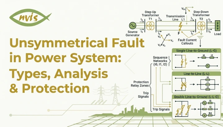
    Single Line to Ground (LG) Fault

    This is the most frequent fault type you will encounter in any power system, and understanding it first makes everything else easier to follow. A single line to ground fault happens when one phase conductor comes into contact with ground, or with a grounded structure like a transmission tower. In the real world, this often happens because a vehicular accident causes one of the phase conductors to fall and come in contact with earth, or it may be caused by tree branches, or it could be caused by flashovers across dusty insulators during rain showers. If you have ever seen a fallen power line during a storm, there is a good chance you were looking at exactly this kind of fault. Because only one phase is disturbed, the other two phases largely retain their normal voltage and current behavior, but the overall system still becomes unbalanced enough to require careful analysis.

    Line to Line (LL) Fault

    A line to line fault occurs when two phase conductors touch each other directly, without involving ground at all. This might happen due to conductor clashing during high winds, insulation failure between two phases, or physical damage that brings two live conductors into contact. Since two phases are shorted together while the third remains isolated from fault, current and voltage relationships look quite different from a single line to ground fault, even though both are classified as unsymmetrical.

    Double Line to Ground (LLG) Fault

    This is where two phase conductors touch each other and simultaneously make contact with ground. It is less common than previous two types but tends to produce more severe fault currents because there are now multiple paths for current to flow, both between two faulted phases and from those phases down to ground. Of standard unsymmetrical fault types, double line to ground fault is generally considered most severe, sitting just below fully symmetrical three phase fault in terms of overall impact on the system.

    Why LLLG Is Not Same as LLL

    Here is a distinction that trips up almost every student the first time they encounter it, so it deserves its own dedicated section rather than being buried inside a definition. A three phase fault, written as LLL, involves all three phases shorting together but does not necessarily involve ground. This is a symmetrical fault. A three phase to ground fault, written as LLLG, involves all three phases shorting together and simultaneously connecting to ground. Some references distinguish between LLL and LLLG faults. In practice, both are symmetrical faults, and whether LLLG produces a higher fault current depends on the system grounding and sequence impedances rather than being universally more severe. The confusing part is that both LLL and LLLG are technically symmetrical, because all three phases are still treated equally in both cases. Whether or not ground is involved does not break symmetry, since ground connection affects all three phases the same way. This is different from LLG, double line to ground fault discussed earlier, where only two of three phases are involved, which is what makes LLG genuinely unsymmetrical. If you keep one rule in your head, make it this one: symmetry depends on whether all three phases are treated identically, not on whether ground is involved. That single distinction resolves most of the confusion between these fault categories.

    Real Reason Unsymmetrical Faults Need Special Math

    At this point you might be wondering why engineers cannot just analyze an unsymmetrical fault the same way they analyze a symmetrical one. The honest answer is that they tried, historically, and it turned into an enormous mess. When a system is perfectly balanced, whether under normal operation or during a symmetrical fault, you can analyze just one phase and assume the other two behave identically, just shifted in time. This is called per phase analysis, and it is the reason three phase power calculations are usually so manageable. The moment a fault becomes unsymmetrical, that shortcut disappears. Each phase now has a different current and voltage, which means you are stuck solving three separate, interconnected equations simultaneously for every single fault scenario. Every different fault type would need its own completely different set of equations, and complexity grows fast. A tool built to compare this exact problem notes that without symmetrical components, each fault type would require solving a different set of simultaneous equations in phase domain, vastly increasing computational complexity and opportunity for error. This is exactly the problem that symmetrical components were invented to solve, and it is why technique has remained the backbone of fault analysis for more than a century.

    Symmetrical Components: Trick That Makes This Manageable

    The method of symmetrical components was developed by an engineer named Charles Leggett Fortescue back in 1918, and it remains, even in 2026, standard technique taught in every power systems course and used in every commercial fault analysis software package. Here is the core idea in plain language. Instead of trying to directly solve three unequal, unbalanced phase currents at once, Fortescue proved that any unbalanced set of three phasors can be broken down into three separate balanced sets, each of which is much easier to analyze individually. Once you solve each balanced set on its own, you simply add them back together to get a real, unbalanced answer. These three balanced sets are: Positive sequence: Three phasors of equal magnitude, spaced 120 degrees apart, rotating in normal a b c sequence. This represents the system behaving exactly like it should under normal balanced conditions, and it is the only sequence present during normal healthy operation. Negative sequence: Three phasors of equal magnitude, also spaced 120 degrees apart, but rotating in reverse a c b sequence. Negative sequence currents only appear when there is an imbalance in the system, which is exactly why protection engineers use them as such a reliable indicator that something has gone wrong. Zero sequence: Three phasors that are equal in magnitude but have no phase displacement between them at all, meaning they all point in the same direction at the same time. Zero sequence current only flows when there is a path to ground, which is why it shows up specifically during ground faults. Think of it like separating a smoothie back into its original ingredients. Once blended, the mixture looks impossible to untangle. But mathematically, symmetrical components let engineers “unblend” unbalanced fault into three clean, separate ingredients, positive, negative, and zero sequence, work with each one individually using simple balanced system math, and then blend results back together at end to get true fault current and voltage at every phase.

    Why This Actually Works: Sequence Networks

    Each sequence component gets its own equivalent circuit, called a sequence network, built from impedances of generators, transformers, and transmission lines in the system. During normal operation, only the positive sequence network carries current, since the system is balanced and there is nothing to trigger negative or zero sequence components. The moment an unsymmetrical fault occurs, three sequence networks get connected to each other at fault location, and exactly how they are connected depends entirely on which type of fault has occurred. This connection pattern is genuinely elegant once you see it laid out. As one educational resource puts it, connecting sequence networks correctly for each fault type is a sort of calculation that has to be done whenever a line is installed or modified, so that protective relaying can be set properly. Here is how three standard unsymmetrical faults translate into sequence network connections: For a single line to ground fault: All three sequence networks, positive, negative, and zero, are connected in series with each other. For a line to line fault: Only positive and negative sequence networks are involved, connected in parallel opposition to each other. Zero sequence plays no role here, because there is no path to ground. For a double line to ground fault: The positive, negative, and zero sequence networks are interconnected according to the double line-to-ground fault conditions. Many textbooks represent this as the positive sequence network connected in series with the parallel combination of the negative and zero sequence networks, but the exact representation depends on the derivation and equivalent circuit used. This is the most complex connection of three, which lines up with the double line to ground being the most severe of standard unsymmetrical fault types. Once you have correct sequence network connection for a given fault type, calculating fault current becomes a matter of straightforward circuit analysis on that connected network, nothing more exotic than Ohm’s law applied to an equivalent circuit.

    A Worked Example: Single Line to Ground Fault

    Theory only really clicks once you have worked through an actual number, so here is a simplified single line to ground fault calculation using the kind of values you would see in a textbook problem or an early lab exercise. Consider a generator with following per unit sequence impedances, all referred to a common base:
    • Positive sequence impedance, Z1 = 0.15 per unit
    • Negative sequence impedance, Z2 = 0.15 per unit
    • Zero sequence impedance, Z0 = 0.05 per unit
    • Pre fault voltage, V = 1.0 per unit
    Since a single line to ground fault connects all three sequence networks in series, total fault current in sequence domain is calculated by dividing pre fault voltage by sum of all three sequence impedances: I1 = I2 = I0 = V / (Z1 + Z2 + Z0) I1 = I2 = I0 = 1.0 / (0.15 + 0.15 + 0.05) = 1.0 / 0.35 = 2.857 per unit Since actual fault current at faulted phase is three times zero sequence current for this specific fault type, total fault current works out to: If = 3 × I0 = 3 × 2.857 = 8.571 per unit This example intentionally uses round, simplified numbers to make the underlying pattern visible. Real fault studies performed by protection engineers use exact system data pulled from generator nameplates, transformer test reports, and transmission line parameters, then run through specialized short circuit analysis software rather than hand calculation. But underlying logic, adding up sequence impedances and dividing into pre fault voltage, remains exactly the same whether you are solving it by hand in a classroom or running it through a computer model for a real substation.

    Effects of Unsymmetrical Faults on Power System

    Understanding what actually happens to a power system during an unsymmetrical fault helps explain why protection engineers take this topic so seriously. Voltage sag and swell: phases involved in fault typically experience a voltage sag, a temporary drop below normal voltage, while unaffected phases can sometimes see a voltage swell, a temporary rise above normal. Sensitive equipment connected anywhere near fault location can be damaged or tripped offline by these swings if protection does not respond quickly enough. Current imbalance and overheating: Because current is no longer evenly distributed across three phases, some conductors and windings end up carrying more current than they were designed for. Sustained current imbalance generates excess heat, which gradually degrades insulation and shortens working life of transformers, motors, and generators connected to the system. Negative sequence heating in rotating machines: This deserves special mention because it specifically affects generators and large motors. Negative sequence current, remember, only exists during unbalanced conditions, creating a magnetic field that rotates in opposite direction to the machine’s normal rotation. This induces double frequency currents in the rotor, which generate intense localized heating that standard thermal protection is not always designed to catch quickly enough. This is exactly why negative sequence relays exist as a dedicated protection element in most modern generator protection schemes. System stability risks: In severe or prolonged cases, an unsymmetrical fault can push generators out of synchronism with the rest of the grid, potentially triggering cascading failures across a wider area if protection systems do not isolate fault fast enough.

    How Engineers Protect Against Unsymmetrical Faults

    Detecting an unsymmetrical fault quickly and isolating it before it causes wider damage is the entire purpose of a protection system, and this is where symmetrical components move from being a purely academic exercise into something engineers rely on every single day. Negative sequence relays specifically monitor for presence of negative sequence current, which, as covered earlier, only appears during unbalanced conditions. Since negative sequence current is essentially zero during healthy balanced operation, even a small amount is a highly reliable signal that something has gone wrong, which is exactly why protective relays utilize symmetric components for fault detection, and specifically why during normal operation, zero sequence current is very small, so a high current value is a convenient and reliable indicator of a ground fault. Distance protection measures impedance between relay location and fault point, and modern distance relays use sequence quantities to correctly classify which type of unsymmetrical fault has occurred, which in turn determines how quickly and in what manner circuit breaker should trip. Differential protection compares current entering and leaving a protected zone, such as a transformer or a section of transmission line, and trips instantly if two do not match within an unbalanced fault scenario, since any mismatch signals that current is escaping through an unintended path. Overcurrent protection with ground fault elements specifically watches for zero sequence current, which as discussed only flows when there is a path to ground, making it particularly effective at catching single line to ground faults quickly. Modern digital relays typically calculate all three sequence components in real time from raw phase currents and voltages they measure, then apply logic based on which sequence components are elevated to determine both fault type and its approximate location. This is the same symmetrical components theory from 1918, still doing exactly the job it was designed for, just running on a microprocessor instead of being worked out with pencil and paper.

    Why This Matters Right Now in India’s Power Grid

    Unsymmetrical fault analysis is not just an exam topic. In 2026, it sits at the center of one of the biggest engineering challenges facing India’s power sector, and understanding why will make the rest of this topic feel a lot less abstract. India has committed to genuinely ambitious renewable energy targets, with Government of India’s vision supporting integration of 450 GW Renewable Energy into National Grid by 2030 and an ambitious target of 2100 GW of Renewable energy by 2047. Solar and wind plants, unlike traditional coal or hydro generators, behave very differently during faults, and unsymmetrical faults specifically create real headaches for inverter based control systems these renewable plants depend on. This is exactly why the Central Electricity Authority, India’s apex technical regulator for the power sector, has built explicit requirements around this exact problem into national grid codes. Generating stations connecting to Indian grid must demonstrate ride through capability for balance and unbalanced faults (LVRT and HVRT), meaning a solar or wind plant has to remain connected to grid and continue operating even while an unsymmetrical fault is occurring nearby, rather than simply tripping offline moment voltage dips or spikes. CEA has also moved to formalize protection coordination across the entire national grid. Under current grid code, a uniform protection protocol is required for users of grid for proper coordination of protection systems in order to protect equipment from abnormal operating conditions, isolate faulty equipment, and avoid unintended operation of protection systems, and this Uniform Protection Protocol applies to all Regional entities, State, Central, and Private Generating Companies, Generating Stations, SLDCs, RLDCs, CTU, STUs, Transmission Licensees, and RPCs connected at 220 kV and above. More recently, CEA has extended this safety first approach into fast growing Battery Energy Storage System space as well. New 2026 regulations require BESS installations to follow a two fault tolerance design, ensuring systems remain safe even in event of two independent failures, along with protection against overcharging, deep discharge, short circuits, and operation beyond prescribed temperature limits, taking effect from April 2027. Put simply, every solar farm, every wind installation, and every battery storage project being commissioned across India right now has to prove, on paper and in testing, that it can survive an unsymmetrical fault without destabilizing the grid. This is the exact topic covered in this guide, now playing out at national scale.

    Career Paths: What This Topic Means for Your Future

    If you have made it this far, there is a good chance the underlying question in your mind is practical: does understanding unsymmetrical faults actually lead anywhere in terms of a career? The honest answer is yes, and demand is only growing as India’s grid gets more complex. Protection and relay engineering is the most direct career path connected to this exact topic. Protection engineers are people who calculate fault currents, set relay coordination parameters, and design protection schemes that keep the grid stable. Entry level protective relay engineer roles in India typically start in range of ₹3 to ₹6 LPA, with senior power systems engineers commanding significantly more, averaging around ₹18.4 LPA nationally and reaching approximately ₹20.5 LPA in cities like Bangalore where demand from grid modernization projects is particularly strong. POWERGRID Corporation of India Limited, a Maharatna public sector enterprise and one of largest transmission utilities in world, remains single largest direct employer for students entering this field through annual GATE based recruitment process, hiring Engineer Trainees and Assistant Engineer Trainees in Electrical and Electronics disciplines with starting pay around ₹50,000 to ₹60,000 per month during training, moving into E2 and E3 executive scales afterward. Beyond POWERGRID, state transmission utilities including HVPNL, RVPNL, and MAHATRANSCO regularly recruit engineers into similar protection focused roles. Global equipment manufacturers with a significant Indian presence, including Siemens, ABB, and Schneider Electric, hire electrical engineering graduates for relay design, testing, and system protection studies, often providing structured training programs that directly build on symmetrical components theory covered in this guide. Relevant skills and tools worth building as a student include familiarity with short circuit analysis software such as ETAP, PSS/E, and DIgSILENT PowerFactory, since these are industry standard platforms used to run exact fault calculations discussed in this guide at real substation scale. A solid grasp of per unit systems, single line diagrams, and relay coordination principles will also serve you well in interviews for these roles. Whether you pursue a core electrical engineering role at a utility, a specialized protection engineering position with an equipment manufacturer, or move into the renewable energy sector where fault ride through compliance is now a mandatory requirement, fundamentals covered in this guide form the technical bedrock entire career path is built on.

    Emerging Trends: Where This Topic Is Headed

    A few developments are actively reshaping how unsymmetrical fault analysis and protection get handled going forward, and being aware of them will serve students well beyond graduation. Grid forming inverters are increasingly being deployed for renewable plants specifically because they handle unsymmetrical faults more gracefully than older grid following inverter designs, actively injecting reactive power to support the grid during a fault rather than simply riding it out passively. Wide area monitoring using synchrophasors is giving grid operators real time visibility into sequence components across the entire network rather than just at a single substation, enabling faster and more coordinated responses to unsymmetrical fault events across large geographic areas. AI assisted fault classification is beginning to supplement traditional sequence component based relay logic, using pattern recognition trained on historical fault data to classify fault type and location even faster than conventional algorithms, though underlying symmetrical components theory remains the foundation these newer systems are built on top of. Extended data retention requirements are also becoming standard practice for renewable installations, with newer CEA technical standards requiring plants to store operational and fault data for extended periods with high resolution recording, specifically to support detailed post fault analysis and continuous improvement of protection settings over time. None of these trends replace fundamentals covered in this guide. If anything, they make a solid understanding of symmetrical components and sequence networks more valuable, not less, because every one of these newer technologies still has to speak the same underlying mathematical language when it comes to describing an unsymmetrical fault.

    Conclusion

    An unsymmetrical fault is ultimately about one simple idea with genuinely far reaching consequences: a three phase power system that suddenly stops treating its three phases equally. Whether that imbalance comes from a single line to ground fault, a line to line fault, or a double line to ground fault, underlying physics creates a mess that direct per phase analysis simply cannot untangle on its own. Symmetrical components solve this by breaking unbalanced mess into positive, negative, and zero sequence networks, each individually balanced and manageable, then recombining results to reveal true fault behavior across every phase. This is not purely theoretical knowledge confined to a textbook chapter. It is exact mathematics running inside every protective relay guarding India’s transmission and distribution network today, and it is the same framework Central Electricity Authority now requires every new solar, wind, and battery storage installation to satisfy before being allowed to connect to the national grid. For a student building a foundation in power systems, mastering unsymmetrical fault analysis is not just about passing an exam. It is about understanding the exact mechanism that keeps lights on across an entire country, and it opens a genuinely strong career path in protection engineering, grid operations, and the renewable energy sector that is actively hiring for these exact skills right now.

    FAQs

    An unsymmetrical fault is a type of short circuit where three phases of a power system are affected unequally, unlike a symmetrical fault which involves all three phases identically. three standard types of unsymmetrical faults in a power system are single line to ground, line to line, and double line to ground faults.

     A symmetrical fault involves all three phases equally and keeps the system balanced even during fault, while an unsymmetrical fault involves only one or two phases and creates an imbalance. Symmetrical faults are rarer but generally more severe, while unsymmetrical faults are far more common, with single line to ground faults alone accounting for roughly 70 percent of all faults in a typical power system.

    Symmetrical components break an unbalanced, unsymmetrical fault into three separate balanced sequence networks, positive, negative, and zero sequence, which can each be analyzed using simple balanced system techniques and then recombined to find true fault current and voltage. Without this method, engineers would need an entirely different, far more complex set of equations for every single fault type.

    Single line to ground fault is by far the most common type of unsymmetrical fault, typically caused by fallen conductors, tree contact, or insulator flashovers, and it accounts for the large majority of faults encountered on real transmission and distribution networks.

    Indian grid codes now require solar, wind, and battery storage plants to demonstrate fault ride through capability for unbalanced faults before connecting to the national grid, directly under CEA regulations. This means the plant must stay connected and continue supporting the grid during an unsymmetrical fault rather than disconnecting immediately, making this exact topic a mandatory compliance requirement for any renewable project commissioned in India today.

    Students with a strong grasp of unsymmetrical fault analysis can pursue protection and relay engineering roles at utilities like POWERGRID, equipment manufacturers such as Siemens and ABB, or renewable energy companies that need to demonstrate grid code compliance. Entry level protective relay roles in India typically start around ₹3 to 6 LPA, with power systems engineers earning considerably more as they gain experience with tools like ETAP and PSS/E.
    Tags: Unsymmetrical Fault in Power System, Unsymmetrical Faults

    How to Use a Programmable DC Power Supply Safely in Student Laboratories

    TL;DR –

    • This blog is designed for students, lab instructors, lab assistants, and educators working in electronics, electrical engineering, physics, and applied science laboratories.
    • Programmable DC power supplies offer precise voltage and current control, making them ideal for modern student experiments but only when used correctly.
    • Following a step-by-step safety procedure (setting current limits first, checking ratings, and enabling output gradually) prevents component damage and accidents.
    • Common mistakes like wrong polarity, reused presets, or adjusting circuits while live can lead to serious safety risks and inaccurate results.
    • Developing disciplined lab habits and respecting built-in protection features ensures safer learning, reliable experiments, and professional laboratory practices.


    Modern student laboratories no longer rely only on basic fixed-output power sources. Electronics, electrical engineering, physics, and applied sciences are growing, and educational institutions are using sophisticated equipment to equip students with practical applications. The programmable DC power supply is one of these vital tools, as it enables controlled and accurate delivery of electrical power to experiments, prototypes, and learning activities.

    Although a programmable DC power supply  is flexible and more accurate, the way it is used may lead to the destruction of the components, inaccurate outcomes, or even severe safety threats. Laboratories with students especially require a high focus on safe operating practice since in most cases the users are still learning to do it by hand.

    This guide explains how to operate a programmable DC power supply safely in student laboratories, covering basic concepts, risk awareness, step-by-step procedures, best practices, and instructor responsibilities. As a student, lab assistant, or an educator, you will find it possible to create a robust safety-first policy regarding laboratory power consumption with the help of this article.

    Related Articles

    1. Choosing the Right Power Supply for Your Lab: A Beginner’s Guide to Bench, Programmable & Variable Units
    2. How Practical Labs Make Technical Education and Skilling Industry-Driven
    3. Why Your Electrical Training Lab Needs Safety Earthing Training Work Bench Today

    What is a programmable DC power supply?
    A programmable power supply DC is an electronic instrument used to generate a regulated, adjustable direct current (DC) output. Compared to simple power supplies where the user only operates the power with a manual knob and has only limited control, the programmable units allow users to control voltage and current levels. Many are digitally controlled, and in most cases, the output profile can be stored or automated.

    Key Characteristics

    • Adjustable voltage and current output
    • Digital control and display
    • High accuracy and repeatability
    • Built-in protection mechanisms
    • Suitable for a wide range of experiments

    In student laboratories, a programmable power supply DC is commonly used for:

    • Circuit analysis and testing
    • Semiconductor experiments
    • Microcontroller and embedded system projects
    • Battery simulation and charging studies
    • Research-oriented lab work

    Understanding the capabilities and limitations of this equipment is the first step toward safe operation.

    Why Safety Matters When Using a Programmable DC Power Supply in Student Labs?

    Even though laboratories are established with a controlled learning environment, it should not be assumed that they are risk-free, particularly in cases where electrical equipment is used. Many students are still learning to understand electrical ratings, polarity, and the practical implications of incorrect settings. A programmable power supply DC can provide substantial power and when not used correctly, it can cause serious problems such as damage to delicate electronic components, short circuits and overheating, electrical sparks or burns, and in severe cases, fire hazards.

    Student laboratory safety is not about limiting experiments. Rather, it is the empowerment of learning in a form which is responsible and organized. By knowing about possible dangers and applying the safety protocols, students not only decrease the risk of accidents, they also develop confidence, technical skills, and professional laboratory practices that will be highly needed in their academic and industrial settings in the future.

    Step by Step Guide to Using a Programmable DC Power Supply Safely in the Lab

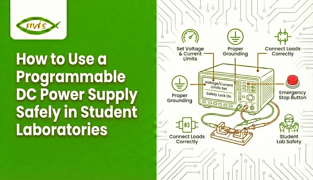
    A consistent operating protocol must be followed when using a programmable DC power supply in student laboratories to ensure safe, stable, and reliable output. Here is the corrected and expanded step-by-step procedure with the missing safety points added.

    Step 1: Keep the Power Supply OFF

    • Never switch ON the supply while connecting or disconnecting a circuit
    • Ensure the output is OFF and knobs are at minimum
    • Check that cables and probes are not damaged

    Step 2: Verify Ratings & Circuit Requirements (Often Missed)

    • Confirm required voltage and current from the circuit diagram
    • Ensure the supply rating is within safe limits
    • Identify correct terminals and channel (if multi-channel supply)

    Step 3: Set Initial Parameters

    • Set voltage to zero or lowest value
    • Set a safe current limit first (component protection step)
    • Clear any old preset or stored program settings

    Step 4: Connect the Circuit

    • Connect with correct polarity (+ to +, – to –)
    • Use proper insulated leads – no loose wires
    • Tighten terminals securely
    • Cross-check wiring with the circuit diagram
    • Get instructor/partner verification (recommended in student labs)

    Step 5: Enable Output & Power On

    • Turn ON the main power
    • Then enable the output channel (if separate button provided)
    • Increase voltage gradually, not instantly
    • Watch voltage/current display while increasing

    Step 6: Monitor During Operation

    • Observe for abnormal signs:
      • Excess current draw
      • Overheating components
      • Smoke or smell
      • Unusual sounds
    • Use multimeter/oscilloscope for verification
    • Do not touch live terminals or exposed conductors
    • Keep liquids and metal tools away

    Step 7: Fault Response (Commonly Missing)

    • If current spikes or a short is suspected:
      • Turn output OFF immediately
      • Do not adjust wiring while live
      • Let components cool before touching

    Step 8: Shutdown Procedure

    • Reduce voltage back to zero
    • Turn output OFF first, then main power OFF
    • Disconnect the circuit safely
    • Reset voltage and current knobs to minimum for the next user

    Step 9: Post-Use Check (Good Lab Practice)

    • Remove leads properly (hold connector, not wire)
    • Report any equipment issues
    • Leave the bench in safe default condition

    Common Mistakes to Avoid When Using a Programmable DC Power Supply

    • Setting voltage before current limit
      Always set the current limit first. If voltage is applied without a defined current limit, sensitive components can burn out instantly during a short or overload condition.


    • Forgetting to turn output OFF before wiring
      Never connect or modify circuit wiring while the output is ON. Live connections increase the risk of short circuits, sparks, and component damage.


    • Reusing previous presets or stored settings
      Programmable supplies can retain earlier configurations. If not cleared, old voltage/current values may be applied unexpectedly and damage the new circuit.


    • Wrong polarity connections
      Reversing positive and negative terminals can permanently damage components like ICs, LEDs, and microcontrollers. Always double-check polarity before enabling output.


    • Jumping directly to the required voltage
      Increasing voltage too quickly prevents you from spotting abnormal current draw early. Always raise voltage gradually while watching the display readings.


    • Ignoring current spike warnings
      Sudden current spikes usually indicate a wiring error or short circuit. Turn the output OFF immediately and inspect the setup before continuing.

    Best Practices for Students

    The safe use of a programmable power supply DC is not just about producing rules and memorizing them, but is also assisting the students to form professional laboratory habits. Students must be able to think with caution, as they need to always read through the instructions of the experiment, ensuring that the necessary level of voltage and current is taken. It is better to start with low settings and raise the settings gradually to minimize the chances of a sudden failure of the components or the destruction of the circuits.

    The protective features built into a programmable DC power supply should never be bypassed, as they are designed to prevent accidents and equipment damage. In case of uncertainty, students need to seek the advice of a lab instructor or assistant as opposed to making assumptions, both to prevent unsafe operation and inaccurate results of an experiment.

    Conclusion

    A programmable DC power supply is both a valuable and necessary instrument in modern student laboratories. It is flexible, precise and highly featured, and therefore suitable in the educational context, but only when it is used properly.

    Through the knowledge of voltage and current control, adhering to the organized operating rules and the consideration of in-built protective measures, students are able to operate a programmable power supply DC with utmost safety and responsibility. In their turn, teachers and laboratory managers are critical to providing support to safe practices and keeping equipment up to standards.

    After all, safety does not inhibit learning, it is the backbone, upon which experimentation, innovation, and discovery can be successful in student laboratories.

    FAQs

    A programmable DC power supply  is a laboratory instrument which provides regulated DC current and voltage. This enables the user to accurately adjust the power output and is good in student experiments, testing circuits and learning electronics in a controlled and safe manner.

    Yes, students may be able to work with a programmable power supply DC safely in case they follow instructions in the lab, establish appropriate limits, and operate under supervision. Experiment safety is also minimized through inbuilt safety features.

    Prior to its activation, verify voltage and current settings, check cables, check polarity and maintain a clean and dry workspace. These inspections assist to avoid short circuiting and equipment destruction.

    The rise in voltage is gradually applied to the circuit to enable students to observe the behavior of the circuit and avoid sudden overloads. This is done to provide protection on sensitive parts and to enhance safety in case a programmable power supply DC is used.

     Current limiting is the setting that limits the current fed to a circuit. It safeguards against overheating, short circuiting, and failure of components and so the programmable power supply DC is safer in the use of the student laboratory.

    Tags: programmable dc power supply, programmable power supply dc

    Choosing the Right Power Supply for Your Lab: A Beginner’s Guide

    An electronic lab cannot run without a dependable Power Supply. Whether you are a student assembling your first circuit, a hobbyist working on a microcontroller project, or an engineer setting up a university or small R&D lab, the correct power source can influence accuracy, safety, and the speed of learning.

    This guide categorizes the most important types of bench, programmable, and variable Power Supplies and provides real-world advice that is easy for beginners to understand, helping you choose the right unit for your specific requirements.

    Understanding the Importance of the Right Power Supply

    One of the most significant choices when establishing an electronics, R&D, or learning laboratory is selecting the right Power Supply. It is not just a device that delivers voltage; it is the foundation that ensures experiments are accurate, components remain protected, and prototypes behave as expected.

    From bench power supplies used for daily prototyping to programmable power supplies for automated testing and versatile variable power supplies for learning and experimentation, the options can feel overwhelming. This guide simplifies those choices so you can confidently select what fits your lab needs.

    Why the Right Power Supply Matters

    A power supply does more than deliver voltage. It provides a predictable and safe source of energy so measurements stay accurate and components remain protected. Using an incorrect or poorly specified supply can result in:

    • Unreliable measurements due to voltage ripple or noise
    • Damaged components from overcurrent or overvoltage conditions
    • Slower development cycles due to lack of repeatable testing features

    Choosing the right lab Power Supply dramatically improves safety, experiment reproducibility, and overall confidence while working.

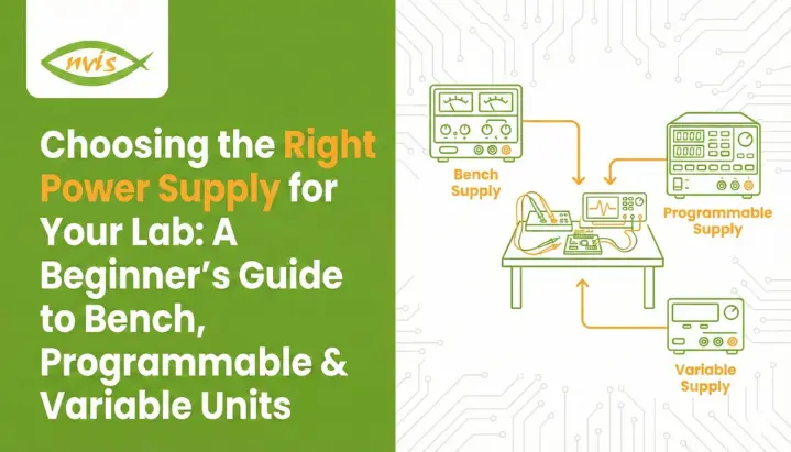
    Main Types of Power Supplies

    Bench Power Supplies

    General-purpose desktop units with one or more outputs, intuitive manual controls, and features suited for education and prototyping.

    Programmable Power Supplies

    Designed for automation and R&D, these supplies support scripting, remote control (USB/LAN/GPIB), and precise repeatable outputs.

    Variable Power Supplies

    Focused on continuously adjustable voltage and current, making them ideal for teaching, experimentation, and learning circuit behavior.

    In practice, these categories often overlap. The key difference lies in where the emphasis is placed: convenience, automation, or learning flexibility.

    Key Specifications You Must Understand

    1. Output Voltage Range: Ensure it covers current and future project needs.
    2. Output Current Capacity: Choose 20–30% headroom over expected load.
    3. Power Rating: Determines suitability for high-demand applications.
    4. CV & CC Modes: Essential for stable and safe operation.
    5. Ripple & Noise: Low ripple is critical for sensitive electronics.
    6. Load & Line Regulation: Better regulation means higher accuracy.
    7. Number of Outputs: Single vs multi-rail system requirements.
    8. Display & Resolution: Improves precision and learning.
    9. Protection Features: OVP, OCP, OTP, and short-circuit protection.

    Programmable Power Supplies: When Automation Matters

    As projects become more complex, repeatability and automated control become critical. Programmable power supplies allow engineers and researchers to automate voltage/current profiles, run timed sequences, and log performance data with high accuracy.

    What Makes Them Different

    • Remote control via software or SCPI commands
    • Scripted voltage and current profiles
    • Higher precision and telemetry

    Example Use-Cases

    • Battery charge/discharge testing
    • Manufacturing test automation
    • Repeatable research experiments

    Beginner-Friendly Comparison

    Bench supplies suit hands-on learning, programmable supplies excel in automation, and variable supplies are ideal for experimentation and teaching.

    Safety Best Practices

    • Always verify polarity before connecting
    • Use current-limited startup for new circuits
    • Keep wiring organized to avoid shorts
    • Turn off supplies before major changes

    Maintenance & Calibration Tips

    • Ensure proper ventilation
    • Inspect connectors and leads regularly
    • Calibrate periodically for accuracy
    • Store in a clean, dry environment

    Final Recommendations

    Beginners should start with a 0–30V, 0–3A bench or variable supply with good protection features. For automated testing, invest in a programmable supply with suitable communication ports and scripting support.

    Conclusion

    Choosing the right Power Supply is an investment in safer, faster, and more accurate experimentation. As projects scale in complexity, programmable supplies help minimize errors and deliver consistent results.

    Nvis Technologies offers advanced engineering education, research, and lab solutions for universities, industries, and technical institutions.

    Tags: AI in Education, Digital Electronics, Experiential Learning, Future Skills, IoT in Schools., Renewable Energy Learning, Robotics, School Innovation, STEM education

    Choosing the Right Power Supply for Your Lab: A Beginner’s Guide to Bench, Programmable & Variable Units

    An electronic lab cannot run without a dependable Power Supply . Whether you are a student assembling your first circuit, a hobbyist working on a microcontroller project, or an engineer setting up a university or small R&D lab, the correct power source can influence accuracy, safety, and the speed of learning.

    This guide categorizes the most important types of bench, programmable, and variable Power Supplies and provides real-world advice that is easy to understand by beginners in order to make the correct selection of the appropriate unit that suits your requirements.

    Understanding the Importance of the Right Power Supply

    One of the most significant choices made in the establishment of an electronics, research and development, or learning laboratory is the choice of the Power Supply. A power supply is not just a machine that delivers a voltage but it is the base that makes sure your experiments are correct, components stay protected and prototypes behave as expected. As an engineering major, a hobbyist, or a professional researcher, the choice of the right unit has a direct influence on the performance, safety, and productivity.

    Whether it is bench power supplies that are intended to be used in everyday prototyping to programmable power supplies that are then used in automated test configurations, or even the very versatile Variable Power Supplies used for learning and experimentation, the choices can be daunting. This guide makes the choice of power supply easy enough in that you are sure to choose the most suitable power supply according to your specific laboratory needs.

    Why the right power supply matters

    A power supply does more than just deliver voltage. It provides a predictable, safe source of energy so that measurements are accurate and components are protected. Using the wrong type or a poorly specified unit can cause:

    • Unreliable measurements due to voltage ripple or noise.
    • Damaged components from overcurrent or overvoltage conditions.
    • Slower development cycles because you don’t have the features needed for repeatable tests.

    Picking the right lab Power Supply dramatically improves experiment reproducibility, safety, and developer confidence.

    Quick overview of the main types

    • Bench power supplies – general-purpose desktop units with one or more outputs, intuitive controls (analog knobs or digital interface), and features aimed at prototyping and education.
    • Programmable power supplies– designed to be controlled by a computer or test system; they support scripting, remote control (USB/LAN/GPIB), and precise, repeatable outputs for automated testing.
    • Variable power supplies – a category often overlapping with bench supplies; emphasizes continuously adjustable voltage/current so users can sweep values for experiments or teaching.

    Practically these categories are overlapping: a large number of bench supplies are variable, and a large number of programmable supplies are physically mounted on the bench. The distinctions are concentrations, i.e. manual convenience (bench), automation and repeatability (programmable), and variable range to learn and experiment (variable).

    Variable Power Supplies

    3 × 0–12V, 40A DC Power Supply – Nvis 1240P

    Nvis 1240P is a high-current, triple-output DC Power Supply designed for power electronics, motor testing, and advanced laboratory applications.

    Know More

    DC Programmable Power Supply – Nvis 1305P

    Nvis 1305P offers precise, programmable voltage and current control, making it ideal for automation, R&D, and long-duration test setups.

    Know More

    AC Power Supply – Nvis 230P

    Nvis 230P is a reliable AC Power Supply built for electrical experiments, AC circuit training, and controlled AC testing environments.

    Know More

    Key specs you must understand

    It is important to understand the specifications that directly affect performance, accuracy, and safety before selecting the appropriate Power Supply to use in your lab. These specifications define the extent of compatibility between the supply and your projects, component security and dependable and consistent power to test and experiment.

    1. Output Voltage Range

    This is the range of voltages the power supply can deliver (e.g., 0–30V). Choose a supply with a range that covers all your typical circuits, with additional headroom for future projects.

    2. Output Current Capacity

    Measured in amperes (A), this defines the maximum current the supply can deliver. Always select a supply with 20–30% higher current than your highest expected load to avoid stress or overheating.

    3. Power Rating (Wattage)

    Voltage × Current = Power. This tells you the total capability of the power supply. Higher-power units can support demanding loads like motors, RF circuits, or power electronic prototypes.

    4. Regulation (CV & CC Modes)

    Constant Voltage (CV): Maintains a stable voltage even if load changes.
    Constant Current (CC): Protects components by limiting current to a set value.
    Understanding how to switch between CV and CC is critical for safe testing.

    5. Ripple & Noise

    Even DC outputs contain small fluctuations. Low ripple and noise are essential for sensitive analog circuits, microcontrollers, and communication systems. High ripple can distort signals and affect measurement accuracy.

    6. Load & Line Regulation

    Load regulation: How well the voltage stays constant as the load varies.
    Line regulation: How stable the output remains when the input power changes.
    Better regulation means more precise results.

    7. Number of Outputs (Channels)

    Single-channel supplies are ideal for simple circuits, while dual or triple outputs are useful for powering multi-rail systems (e.g., 5V, 12V, -12V simultaneously).

    8. Display & Resolution

    High-resolution digital displays help you set voltage and current more accurately. This is especially important for precision testing, low-power circuits, and educational environments.

    9. Protection Features

    • OVP (Over-Voltage Protection)
    • OCP (Over-Current Protection)
    • OTP (Over-Temperature Protection)
    • Short-circuit protection

    Programmable power supplies: when automation and precision matter

    With increased complexity in electronics projects, repeatability, automated power control with high accuracy is needed. This is where the programmable power supplies differ with the traditional bench units. Engineers and researchers are able to automate voltage and current settings, run timed sequences and collect detailed performance information which significantly improves testing efficiency and reliability compared to manually adjusting knobs.

    Programmable supplies are particularly useful in laboratories that need uniformity in repeat cycles of a test, or where there is a need to test the behavior of devices under different power conditions.

    What makes them different

    • Remote control via software or SCPI commands.
    • Ability to run scripts that change voltages/currents over time (sweeps, ramps, profiles).
    • Often higher precision and richer telemetry (logging voltage, current, temperature).

    Features to prioritize

    • Communication ports compatible with your test setup (USB/LAN/GPIB).
    • Support for SCPI or a vendor API for scriptable control.
    • Fast transient response and tight regulation for power electronics testing.
    • Logging and built-in test sequences.

    Example use-cases

    • Battery testing with automated charge/discharge cycles.
    • Manufacturing test rigs where devices are validated through scripted tests.
    • Research experiments requiring repeatable, time-based voltage/current profiles.

    Comparison Table (Beginner-Friendly)

    Characteristic Bench Power Supply Programmable Power Supply Variable Power Supplies
    Best for Prototyping, education Automated tests, R&D Teaching, experiments
    Manual control Excellent Possible (less focus) Excellent (fine control)
    Automation Limited Strong Limited
    Precision Good Very good / excellent Good
    Typical price Low–medium Medium–high Low–medium
    Safety features Usually included Advanced options Usually included
    Recommended when You want quick hands-on work You need repeatable, scripted control You want to sweep and learn behaviors

    Safety best practices (non-negotiable)

    • Always check polarity before connecting; reverse polarity can destroy parts.
    • Use banana leads or safety-shrouded connectors for bench work.
    • Keep exposed connectors and wiring neat to avoid shorts.
    • Use current-limited startup when connecting new or unknown loads.
    • Turn off supplies before making major wiring changes.
    • For student labs: label rails and leave a prominent guide on safe operating ranges.

    Maintenance & calibration tips

    • Keep ventilation unobstructed—supplies generate heat.
    • Periodically inspect leads and connectors for wear.
    • Calibrate periodically if you need measurement-grade accuracy (institutional labs typically recalibrate annually).
    • Store in a dry, dust-free environment when not in use.

    Final recommendations

    If you’re just starting and need hands-on learning: buy a solid bench or variable power supply with at least 0–30V/0–3A and good protection features. This combination covers most student projects.

    If you plan to automate tests or need repeatable profiles: prioritize a programmable power supply with the communication ports you will use (USB or LAN) and scriptability (SCPI).

    For mixed needs (education + occasional automation), consider a mid-range programmable bench supply that offers both manual controls and remote interfaces.

    Choosing the right Power Supply is an investment in safer, faster, and more accurate experimentation.Most beginners find that a variable power supply with basic control features offers the best balance of flexibility, safety, and ease of learning, safety, and learning. The more sophisticated your projects are or the more automation that has been added, the more programmable supplies that can be added to your bench can assist in scaling your testing, minimize human error, and produce repeatable results.

    As a final note, Nvis Technologies offers advanced engineering education, research, and lab solutions for universities, industries, and technical institutions to universities, industries and technical institutions.

    Frequently Asked Questions (FAQs)

    1. What is the difference between a bench power supply and a variable power supply?

    A bench power supply is a general-purpose laboratory device used for everyday prototyping and testing.
    A variable power supply specifically allows users to continuously adjust voltage and current over a wide range,
    making it ideal for experimentation, learning, and testing circuit behavior under different conditions.
    Many bench supplies are also variable, but not all variable supplies are intended for advanced lab applications.

    2. How do I choose the right voltage and current rating for my power supply?

    First, determine the maximum voltage and current required by your project. Then add a 20–30% safety margin
    to ensure reliable operation and avoid stressing the power supply. For example, if your circuit requires
    12V and 1A, choose a unit rated for at least 15V and 1.3A or higher.

    3. When should I choose a programmable power supply instead of a basic bench unit?

    A programmable power supply is recommended when your work involves automation, SCPI scripting, or precise,
    repeatable power sequences such as battery testing, endurance testing, or automated production workflows.
    For general prototyping or student laboratories, a standard bench or variable power supply is usually sufficient.

    4. Why are ripple and noise important in a power supply?

    Ripple and noise are unwanted AC fluctuations present on a DC output. Excessive ripple can cause interference,
    unstable measurements, or malfunction in sensitive circuits such as ADCs, sensors, and RF modules.
    Low-ripple power supplies are essential for precision and analog electronics work.

    5. What safety features should I look for in a lab power supply?

    Key safety features include Over-Voltage Protection (OVP), Over-Current Protection (OCP),
    Over-Temperature Protection (OTP), and short-circuit protection. These features safeguard both
    your electronic components and the power supply, especially when testing new or unknown circuits.

    Tags: Power Supply, Power Supply Variable

    Request a Callback

    Please enable JavaScript in your browser to complete this form.

    No spam. Just a quick call.

    =