


Head Office
141-A, Electronic complex, Pardesipura,Indore - 452010 India
Phone: +91 73899 00887 , +91 98932 70303
Email:info@nvistech.com
Toll Free
+91 73899 00887
Working Hours
We are happy to meet you during our working hours. Please make an appointment.
- Monday-Saturday: 9:00 AM - 5:30 PM (IST)
- Sunday: Closed
Head Office
141-A, Electronic complex, Pardesipura,Indore - 452010 India
Phone: +91 73899 00887 , +91 98932 70303
Email:info@nvistech.com
Toll Free
+91 73899 00887
We are happy to meet you during our working hours. Please make an appointment.
- Monday-Saturday: 9:00 AM - 5:30 PM (IST)
- Sunday: Closed
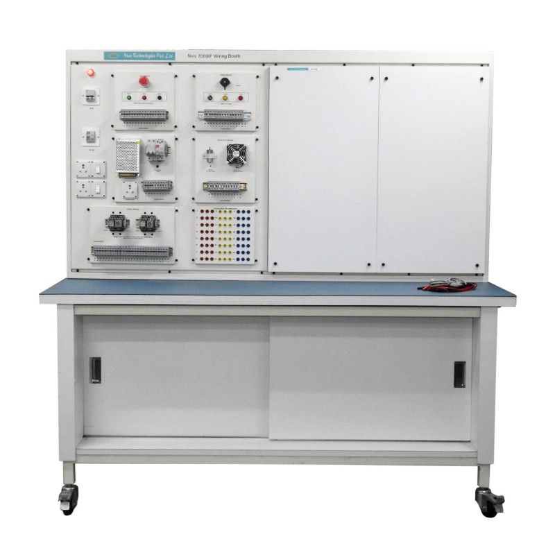
Electrical wiring booth system
Nvis 7059IF
Product Description
- The Work Bench is made of M.S. Powder coated mild steel with Laminated Wood based Top on the working area.
- The basic frame work is made of 30 x 30 x 2 mm tubular mild steel
- The complete Work Bench is made of M.S. (except the Top) and Powder Coated in two Colours for better aesthetic looks
- The overall dimensions of Work Bench / Test Bench W = 1500 mm; D = 900 mm; H =1500mm
- Top: 25mm thick work top made from laminated wood based plain particle board with one Side post forming (round profile).Remaining three sides of the work top is lipped with PVC Edge band.
- Wiring panel at the back above the table top height with 6 separate Modular sets of 5 Amp Switch & 5 pin Child proof protective Socket are provided on the panel.
- Set of 4 Pole MCB (32A) for 3fON / OFF for the whole table and Hi Bright 3. R, Y, B Phase indicators & 15A fuse for each phase are provided on the panel
Power Module
- 1x 3-pin power cable (220-240V AC)
- 1x terminal block to connect in-coming wires
- 1x Miniature Circuit breaker (100-240V AC) 6A
- 1x RCCB 32A 30mA
- 1x DC power supply from 220-240V AC to 24V DC min 2.2A
- 1x resettable Fuse with holder (24V, 2A)
- 3 x 3-way Terminal block mounted on the 35-mm DIN Rail
- Complete and neat wiring connection among the 3-pin socket, circuit breaker, voltage converter, fuse and terminal blocks.
Input Module
- 3 momentary buttons – Green, Red & Black
- 1 E-Stop switch
- 1x 35-mm width DIN Mounting Rail (length 120mm)
- 4 x 3-way Terminal Blocks mounted on the 35-mm DIN Rail
- Complete and neat wiring connection in such the way that:
Output Module
- 3x 24V-lights – Green, Yellow & Red
- 1x Buzzer (24V)
- 1x 35-mm width DIN Mounting Rail (length 120mm)
- 4 x 3-way Terminal Blocks to be mounted on the 35-mm DIN Rail
- Complete and neat wiring connection in such the way that:
Control Module
- 1x printed label (must be engraved) “Control”
- 2x 35-mm width DIN Mounting Rail (length 270mm)
- 4 x PYF14A-E Socket w/ pin configuration as in the picture. The socket can be mounted onto the 35-mm DIN Rail
- 2 x relay (4 poles, 5A, 24VDC) w/ pin configuration as in the picture. It can be mounted onto the above PYF14A-E Socket
- 2 x timer (4 poles, 5A, 24VDC, 60 sec) w/ pin configuration as in the picture. It can be mounted onto the above PYF14A-E Socket
- 9 x 3-way Terminal Blocks mounted on the 35-mm DIN Rail
Motor & Fan Module
- 1x printed label (must be engraved) “Motor & Fan”
- 1x 35-mm width DIN Mounting Rail (length 120mm)
- 1 DC motor (24VDC) with reduction gear mounted to drive a wheel as shown in the picture. The output shaft runs at 120 to 200 rpm on 24VDC.
- 1 DC Fan (24VDC)
- 3 x 3-way Ferrule Terminal Blocks mounted on the 35-mm DIN Rail for motor and fan.
- Request Quote
- Technical Specification