






TL;DR
- This blog is for Indian engineering and diploma students, GATE, SSC JE and RRB JE aspirants, and lab in-charges who want to understand what a digital logic trainer kit contains, which experiments can be performed on it, and how to choose a board that matches their syllabus without overspending.
- A digital logic trainer kit (also referred to as a digital logic trainer board) contains a regulated 5 V power supply, logic switches, LED indicators, a clock source and IC sockets or a breadboard, for testing real logic chips (such as 74LS00) without first constructing support circuits.
- The characteristics that determine the usefulness of a board are: supply rating, switch debouncing and polarity, available clock range and manual pulser, mounting of the ICs, and number of available switches and LEDs.
- If you’re purchasing or accepting delivery, run the NAND-only XOR test and a pin-count check below. These quick checks can reveal wiring, power-supply, and input-count issues.
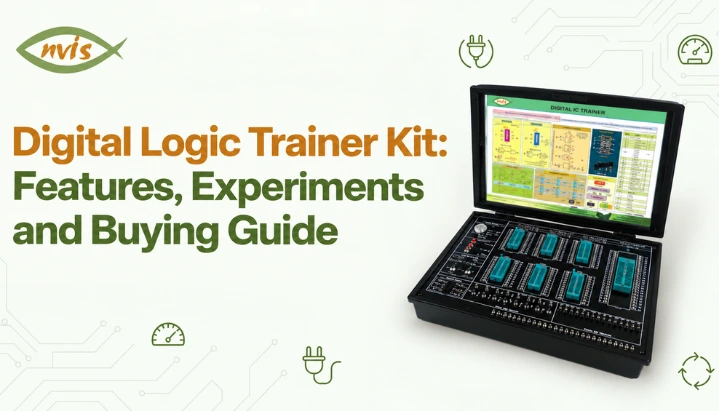
A digital logic trainer kit is a portable or bench top board which provides power, inputs, outputs and clock to make and test circuits using any standard logic ICs. The same instrument is marketed by vendors with many different names like digital logic trainer board, digital IC trainer, logic gates trainer and digital electronics trainer. A common thread is a board on which a student can wire real chips and see real voltage levels on LEDs.
Digital electronics is offered in second or third year throughout the electronics, electrical, instrumentation and computer courses and a lot of the time hardware wiring is demanded in the lab. One of the most popular ICs to use in any lab experiment is a quad 2-input NAND gate, (74LS00), which requires a power supply ranging from 4.75V to 5.25V as specified by Texas Instruments in their datasheet. A trainer board is a tool that supplies that and all around the chip.
Most of the product pages for these boards provide specifications but do not provide any explanation of what each of the specifications mean for an experiment and seldom provide any sense of what a fair price is. This is an explanation of each feature in simple words, a demonstration of how to use a trainer board through two numerical problems and an example of dividing a clock, a summary of Indian listing prices in October 2026, and a buying framework and pre purchase test. Near the end, the coverage of exam relevance for GATE, SSC JE and RRB JE is provided.
Also Read,
- Half Adder: Circuit, Truth Table, Working & Applications
- What Is a Full Adder? Circuit, Truth Table & Working – Nvis
- Arduino Embedded System: Set Up Your First Lab Project
What Is a Digital Logic Trainer Kit and How Is It Different From a Breadboard?
There are three things a logic IC must have before it can do some useful work. It requires power, means to set its inputs to logic 0 or 1, and means to view its outputs. A plain breadboard provides connection points for components, but it does not provide the power supply, switches, LEDs, clock source, or other supporting circuits needed for a complete digital logic experiment.
A trainer board prebuilds these supporting circuits and brings them to labelled terminals. The student can then insert the IC, connect switches to its inputs and connect outputs to LEDs, allowing the focus to remain on the logic being tested.
What Are Three Types of Digital Logic Trainer Boards?
Digital logic trainer boards are commonly available in three broad physical designs: fixed-gate trainers, socketed IC trainers, and breadboard-based trainers. First is the fixed gate trainer, where gate ICs are permanently mounted on board and only their terminals are brought out. One manufacturer’s logic gates circuit trainer, for example, lists four AND, four OR, four NAND and four NOR gates, six NOT gates and a dual J K flip flop on board, with four debounced logic switches and a breadboard area for adding more.
The second is socketed IC trainer, where a student inserts any compatible IC into a socket on panel. One manufacturer’s digital electronic trainer lists IC bases for 16 pin and 28 pin devices, and others use zero insertion force (ZIF) sockets so pins do not bend after repeated changes. Third is the breadboard trainer, where a large solderless breadboard sits beside switches, LEDs and power rails, and students plug ICs into it directly. One manufacturer’s TTL trainer built on 74 series describes a large breadboard area on its front panel for exactly this purpose.
Fixed-gate boards are generally less flexible because the available gates are built into the board. Socketed and breadboard-based trainers usually offer greater flexibility for experiments involving different ICs, although pricing and capabilities vary by model, which is why the number and type of sockets deserves a line of its own on any comparison sheet. NvisTech’s guide to how a digital IC trainer kit is built and used in labs goes deeper into ZIF socket mechanism and lab usage if that background is new.
What Features Does a Digital Logic Trainer Board Have?
The features below are common on many trainer boards, although the exact combination varies by model. A useful skill is knowing which numbers to read on a product page and what a good value looks like.
Why Does Power Supply Rating Matter?
The 74LS family expects a supply between 4.75 V and 5.25 V, which is 5 V with a tolerance of 5 percent. Inputs are read as logic 1 above 2 V and as logic 0 below 0.8 V, again according to the TI datasheet for SN74LS00. An unstable or noisy supply can cause unreliable circuit operation and may lead to incorrect or fluctuating outputs that students sometimes mistake for a faulty IC.
Listings for Indian trainers commonly state a fixed 5 V supply rated at 1 A with load regulation of about 1 percent, and more complete boards add a variable or dual rail. One TTL trainer lists a fixed 5 V rail plus a 0 to ±18 V output, with ripple and noise below 2 mV. extra rail is useful for data converter experiments and for CMOS parts that tolerate a wider supply, but each CMOS IC has its own limits, so the datasheet decides what is safe.
How Do Logic Switches and Pulsers Work?
Logic switches set inputs. A good board labels each switch and holds a clean logic 0 or logic 1 at its terminal. A separate push button, manual pulser, produces exactly one clean pulse per press, and that is what makes flip flops and counters observable.
The word to look for on a specification sheet is debounced. A mechanical switch does not close once. contacts bounce a few times in a few milliseconds, much like a ball that hits floor several times before it settles, and a counter treats each bounce as a separate clock pulse. A debounced pulser filters this out so one press means one count.
Switch polarity also deserves a quick check. A university lab manual for one logic trainer board warns that switch in off position actually represents logic 1 on that board. Printed labels and real voltages do not always agree, so reading an LED against a known input is worth doing on any new board.
What Do LED Indicators and Displays Do?
Each LED shows a logic level at its terminal, and some boards buffer these indicators so connecting an output to an LED does not load the IC. One trainer lists eight buffered logic level indicators, and another lists sixteen 5 mm red LEDs together with a four digit seven segment display that has its own decoder driver. A built-in display with a decoder saves wiring a BCD to a seven segment IC for counter experiments, although an experiment that uses that IC then needs an external display.
What Clock Range Does a Trainer Board Need?
Sequential circuits need a clock. Listings show two very different approaches. One TTL trainer offers a variable clock from 1 Hz to 1 MHz in three ranges, while a logic gates trainer from another maker lists fixed clocks of 100 kHz, 10 kHz and 1 kHz. A hobbyist board sold online goes the other way with a 0.2 Hz to 5 Hz clock and manual stepping, because it is built only for visible sequential logic.
A second numerical example later in this article shows why a board whose slowest clock is 1 kHz cannot show a counter counting without extra dividers or manual pulser. The slow end of the clock range is the number to read first.
How Are ICs Connected, and What Else Is on Board?
Connections are made with patch cords into 2 mm sockets on many Indian boards, and one manufacturer’s listing specifies a set of 20 coloured multi strand cords with 2 mm stackable plugs. Others rely on breadboard jumper wires. Banana style 2 mm sockets are sturdier for a shared lab, while a breadboard is cheaper and more flexible for a student working alone.
Optional extras show up on better boards. A built in digital voltmeter of 0 to 20 V is useful for confirming supply levels and logic thresholds, a logic probe with pulse capture helps trace signals, and a mains switch with an indicator and a fuse protects the board itself.
How Do You Use a Digital Logic Trainer Kit Step by Step?
The same sequence works for any experiment, and following it in order prevents most of the damage students do to chips.
Start with the board switched off and IC out. Identify supply pins on IC from its datasheet, because connecting them wrong way round can destroy chips. Insert IC with notch facing right direction, then switch board on and measure supply rail with a multimeter or built in voltmeter before trusting it.
Connect VCC and GND first, and only then wire inputs and outputs. Patch each input to a logic switch, patch each output to an LED, and step through the truth table one row at a time, writing down LED state after each change. For a sequential circuit, apply a manual pulser once per step rather than letting a fast clock run.
Unused inputs on TTL gates should be tied to a defined level through a switch or a rail. A floating TTL input tends to behave as logic 1, but it is also sensitive to noise, and that is a common source of outputs that change when someone touches the board.
How Do You Build an XOR Gate From NAND Gates on a Trainer Board?
This worked example is useful for two reasons. It practises full wiring procedure on one IC, and it is also a standard exam style problem on universal gates.
Problem. Build a 2 input XOR gate using only four NAND gates in a single 74LS00 and verify its truth table on a trainer board.
Step 1: Write logic. Let inputs be A and B and output be Y. Define four NAND outputs, N1 = (A·B)’, N2 = (A·N1)’, N3 = (B·N1)’ and Y = (N2·N3)’. Here a prime means logical complement and a dot means AND.
Step 2: Prove it algebraically. Using De Morgan’s theorem, N2 = (A·(A’ + B’))’ = (A·B’)’ because A·A’ = 0. Similarly N3 = (A’·B)’. Then Y = N2′ + N3′ = A·B’ + A’·B, which is A ⊕ B. NvisTech’s explainer on Boolean algebra and De Morgan’s theorem covers identities used here.
Step 3: Map pins. On 74LS00, gate 1 uses pins 1 and 2 as inputs and pin 3 as output. Gate 2 uses pins 4 and 5 with output on pin 6. Gate 3 uses pins 9 and 10 with output on pin 8, and gate 4 uses pins 12 and 13 with output on pin 11. VCC is pin 14 and GND is pin 7.
Step 4: Wire it. Connect switch A to pins 1 and 4, and switch B to pins 2 and 9. Connect pin 3 (N1) to pins 5 and 10. Connect pin 6 (N2) to pin 12 and pin 8 (N3) to pin 13. Connect pin 11 (Y) to an LED. Connect pin 14 to the board’s 5 V rail and pin 7 to ground first.
Step 5: Verify truth table. Step through four input rows and compute each stage.
| A | B | N1 = (AB)’ | N2 = (A·N1)’ | N3 = (B·N1)’ | Y = (N2·N3)’ |
| 0 | 0 | 1 | 1 | 1 | 0 |
| 0 | 1 | 1 | 1 | 0 | 1 |
| 1 | 0 | 1 | 0 | 1 | 1 |
| 1 | 1 | 0 | 1 | 1 | 0 |
LEDs should light only when A and B differ. If it does not, check polarity of switches, supply, and pin numbering, in that order.
How Many NAND ICs Does a Full Adder Need?
Problem. How many 74LS00 ICs are required to build a full adder using only 2 input NAND gates?
A full adder has sum S = A ⊕ B ⊕ Cin and carry Cout = A·B + (A ⊕ B)·Cin. first XOR block above uses four NAND gates and produces A ⊕ B, and its first gate already gives (A·B)’. second XOR block takes A ⊕ B and Cin, uses four more NAND gates, and its first gate gives ((A ⊕ B)·Cin)’. Then Cout = [(A·B)’ · ((A ⊕ B)·Cin)’]’, which is one more NAND gate.
That makes 4 + 4 + 1 = 9 gates. Each 74LS00 holds four, so the answer is ceiling of 9 divided by 4, which is 3 ICs, with three gates left spare. This reuse of internal NAND outputs is a point of question and a typical exam trap, since a student who builds two complete XORs and a separate carry circuit counts far more gates than needed.
How Does Trainer Clock Help in Studying a 74LS90 Decade Counter?
74LS90 contains separate divide-by-2 and divide-by-5 counter sections. To configure it as a decade counter, connect the QA output to the clock input of the divide-by-5 section and apply the external clock to the divide-by-2 section. This configuration produces a BCD counting sequence from 0 to 9. The datasheet also describes a symmetrical divide by ten arrangement, where QD feeds input A and clock goes to input B, which gives a square wave at QA.
Problem. A trainer board has a fixed 1 kHz clock. How long does each count last, and how many 74LS90 stages bring output down to 1 Hz?
At 1 kHz, each clock period is 1 ms, so each count state lasts 1 ms and a full 0 to 9 cycle lasts 10 ms. LEDs appear continuously lit, which makes counting impossible to read.
Each 74LS90 stage divides frequency by 10. One 74LS90 stage can divide the frequency by 10, giving 100 Hz from a 1 kHz input. Two stages give 10 Hz, and three stages give 1 Hz. At a 1 Hz counting rate, a complete 0-to-9 cycle takes 10 seconds, making the sequence easier to observe on LEDs. A fixed 1 kHz trainer would therefore need additional divider stages, while a manual pulser can be used when individual count steps are preferred. This is a concrete reason to read the lowest clock frequency on a specification sheet. NvisTech’s explanation of synchronous and asynchronous counters explains why 74LS90 is an asynchronous (ripple) counter and what that means for timing.
Which Experiments Can You Run on a Digital Logic Trainer Kit?
A socketed or breadboard trainer covers the whole standard digital electronics lab list. table groups common experiments with typical ICs from 74 series and what each one demonstrates.
| Experiment | Typical ICs | What it demonstrates |
| Logic gate verification | 7400, 7402, 7404, 7408, 7432, 7486 | Truth tables and universal gates |
| Boolean laws and De Morgan’s theorem | 7400, 7402, 7404 | Algebraic identities on hardware |
| Half and full adders, 4 bit adder | 7486, 7408, 7432, 7483 | Binary addition and carry |
| Magnitude comparator | 7485 | Greater, less or equal for 4 bit numbers |
| Multiplexer, demultiplexer, decoder | 74151, 74138 | Data routing and function implementation |
| Priority encoder | 74147, 74148 | Encoding when several inputs are active |
| BCD to seven segment decoding | 7447 | Driving a display from binary data |
| Flip flops | 7474, 7476 | Edge triggering, preset and clear |
| Counters | 7490, 7493 | Decade and binary counting |
| Shift registers | 7495 | Serial and parallel data movement |
Vendor experiment lists also include Gray code converters, parity checkers, ring counters and decade counters, so the same board often runs them without any extra hardware. NvisTech’s article on experiments and how to choose a digital electronics trainer kit gives full procedures, so this guide concentrates on board features and buying instead. For flip flop theory before the lab session, guide to flip flops in digital electronics is a useful prerequisite, and digital electronics projects for students show where to go after standard experiments.
How Many Switches and LEDs Does a Board Need?
Pin counts decide this, and product pages almost never spell it out. A 74LS83 4 bit adder takes four A inputs, four B inputs and a carry in, which is 9 inputs, and it produces four sum bits and a carry out, which is 5 outputs. A board with only 8 switches cannot drive both operands and carry in at once, so carry in has to be tied to ground permanently.
A 74LS151 8-to-1 multiplexer requires 8 data inputs, 3 select inputs, and a strobe/enable input, giving 12 external control or data inputs. A 4 bit comparator such as 7485 takes eight data inputs plus cascade inputs. Sixteen switches and sixteen LEDs provide enough direct I/O for many of these experiments, although some circuits may still require additional connections or external component while an 8 switch board limits experiments that can be wired without extra tricks. IC functions above come from manufacturers’ datasheets, so confirm pin counts for exact parts before relying on this arithmetic.
What Does a Digital Logic Trainer Kit Cost in India?
Indian prices vary widely because the same name covers boards with very different features. table summarises listings seen on IndiaMART, Amazon.in and manufacturers’ pages in October 2026. Some listings state prices excluding GST, and listed prices are not final quotes, so treat these as a rough guide.
| Listing | Observed price | Notes from listing |
| Basic logic gate trainers (Ahmedabad listings) | About ₹1,500 to ₹1,700 | Fixed gate boards, minimal features |
| Digital logic gates trainer kit (IndiaMART) | ₹1,999 | Entry level |
| Logic gate and IC trainer kits (Amazon.in) | About ₹2,300 to ₹4,500 | Some show a higher M.R.P. |
| Digital IC trainer (Ambala maker) | ₹3,500 excluding GST | Pan India delivery stated |
| Logic gates digital electronics trainer (Hyderabad) | ₹3,810 | 5 V, 1 A supply and fixed 1 kHz, 10 kHz, 100 kHz clocks |
| Digital IC trainer kits (Bengaluru maker) | ₹6,800 to ₹8,600 | Several models, one with a two digit BCD display |
| Digital logic trainer, model PHY 450 | ₹7,200 excluding taxes | Made in India |
| Digital IC trainer with dual colour LEDs | ₹12,500 | Higher end model of same range |
| Digital logic trainer, model 1005B | ₹14,500 | Seven segment display |
| Digital logic trainer (TTL) kit (Jaipur maker) | ₹16,500 | Approximate listed price |
| Digital logic troubleshooting trainer | ₹1,15,000 | Specialised fault finding trainer |
The pattern is consistent. Entry boards sit below about ₹4,500, mid range boards cluster between about ₹6,500 and ₹8,600, advanced boards run from ₹12,500 to ₹16,500, and specialised trainers go beyond ₹1 lakh. Features loosely follow price but not strictly, and listing texts are inconsistent, which is why a price should only be compared after checking the same set of specifications. Imported options also exist, such as a US priced digital logic trainer kit with a built in breadboard listed at $110 after a discount from $150, but import duties and warranty support make local makers easier for institutions.
How Do You Choose the Right Digital Logic Trainer Board?
Match board to situation rather than to the longest feature list.
A student practising at home before lab sessions needs gate verification, flip flops and small counters. An entry or lower mid range board with a breadboard and a debounced pulser is enough, and paying for a variable rail or a voltmeter adds cost without adding learning. A college lab buying many units needs sockets, a wide clock range, sturdy 2 mm terminals and a manual with an experiment list. One Indian procurement style specification asks for more than 30 types of ICs, epoxy glass boards with silk screened circuit diagrams, and an experiment manual with an answer key, which shows how detailed lab tender requirements get.
Diploma and ITI labs sit in between and benefit most from boards that survive heavy use. A GATE, SSC JE or RRB JE aspirant does not need to own a board at all if the course lab covers experiments, and a free browser simulator can handle the rest of practice. One open source browser simulator describes sixteen input switches, sixteen LEDs, selectable clocks of 0.5, 1, 5 and 10 Hz and more than 25 standard 74xx series ICs.
The table lists what to ask a seller before ordering.
| Specification | What to ask | Why it matters |
| Supply | Is 5 V rail regulated, and what is its current rating and ripple? | 74LS ICs need 4.75 V to 5.25 V |
| Switches | How many are there, and are they debounced and polarity labelled? | Wrong polarity gives a reversed truth table |
| Pulser | Is there a debounced single pulse button? | Needed to step flip flops and counters |
| Clock | What are the lowest and highest frequencies? | A slowest clock of 1 kHz cannot be watched on LEDs |
| Inputs and outputs | Are there at least 12 switches and 8 LEDs? | A 4 bit adder or an 8 input multiplexer needs them |
| ICs and mounting | Fixed gates, sockets or a breadboard? | Fixed gates limit experiments |
| Connectors | Are patch cords included and what are socket size and count? | Missing cords delay first session |
| Manual | Does it list experiments with circuit diagrams? | Saves lab preparation time |
| Spares and support | Are replacement ICs available and what is the warranty? | LS family is an older line, and TI’s own SN74LS00 ordering table marks some package variants obsolete |
| Invoice | Is GST included and is a proper invoice issued? | Institutions need it for accounts |
On delivery, run NAND only XOR example and pin count check. A board that reproduces the XOR truth table correctly on a 74LS00 provides a quick check of the supply, switch inputs, IC connections and output indicators involved in that particular test. A pulser test with a 74LS74 or 74LS90 then confirms that single presses give single counts.
NvisTech’s own NV6550 Digital IC Trainer is built around ZIF sockets, logic switches, LED indicators and an onboard clock generator for this experiment range, and guide to what a digital electronics laboratory should include lists instruments that go beside it.
Digital Logic Trainer Board, Breadboard, Simulator or FPGA Board: Which Should You Use?
Each option verifies something different, and most students need two of them.
| Option | What it verifies | Strength | Limit |
| Digital logic trainer board | Real voltage levels and wiring | Complete setup, quick to start | Fixed supply and limited sockets |
| Plain breadboard with ICs | Real behaviour with custom wiring | Cheap and flexible | Supply, switches and LEDs must be built |
| Software simulator | Ideal logic only | Free, instant, no damage risk | Hides wiring faults and timing issues |
| Simulator plus data acquisition hardware | Software defined instruments | Reusable across subjects | Needs separate hardware and software licences |
For example, software-and-data-acquisition platforms can support digital experiments when combined with compatible hardware. However, these setups require separate hardware and software and are more complex than a standalone trainer board. A simulator is the cheapest way to check a design before the lab, and the trainer board confirms that the design works with real chips. Neither fully replaces the other for lab practical examinations, which usually ask for wiring on hardware.
Does a Digital Logic Trainer Kit Help With GATE, SSC JE and RRB JE?
A trainer board is lab equipment, so no exam asks about one. concepts it demonstrates are examined directly, and wiring them once makes truth tables and timing easier to recall. Digital logic appears in published syllabi as follows.
| Exam | Where digital logic appears | Note |
| GATE ECE | Digital Circuits section: number representations, combinational circuits (Boolean algebra, K map minimisation, logic gates, arithmetic circuits, code converters, multiplexers, decoders), sequential circuits, data converters and memories | Check official paper PDF for current year |
| GATE IN | Digital electronics including combinational logic and minimisation of Boolean functions | Verify full list in official PDF |
| SSC JE | Electronics and Telecommunication stream lists digital electronics, sequential and combinational logic, and data conversion and codes | Electrical stream syllabi mention logic gates under basic electronics |
| RRB JE (Electronics and Allied) | Number systems and binary codes, Boolean algebra and logic gates, combinational and sequential circuits, A/D and D/A converters, counters, memories | Confirm against latest RRB notification |
Questions on universal gates, such as XOR from NAND gates and full adder gate count above, fit this syllabus directly. Counter modulus and clock division, as in 74LS90 example, appear as numerical problems. Weightage figures for digital circuits differ from one coaching website to another, and sources also disagree about what changed in GATE ECE 2027 syllabus, so official GATE site at gate2027.iitm.ac.in and SSC and RRB notifications should be the final reference. The syllabus summary should be treated as a general reference rather than a substitute for the latest official notification or syllabus document. Always verify the current requirements on the respective exam authority’s website.
Which Digital Logic Trainer Kit Should You Buy?
The right board is one whose switch count, clock range and mounting style match experiments that will actually be run. Entry-level boards around ₹4,500 or below may be sufficient for basic gate and flip-flop experiments, while mid-range and advanced boards can offer additional sockets, clock options, displays, and connectivity. The right price range depends on the experiments and ICs included in the syllabus.
Two checks protect against a poor purchase. Count switch and LED pins for largest IC in syllabus, since a 4 bit adder alone needs 9 inputs. Then read the slowest clock frequency, because a counter that cannot be watched is of little use. The NAND-only XOR test provides a quick initial check of the power supply, switches, IC socket connections, and LED indicators, but it does not verify every function on the board. Students who want hardware practice without buying anything can start with a course lab and a simulator, and those equipping a lab can compare NV6550 Digital IC Trainer against the specification table above.
FAQs
What is the difference between a digital logic trainer kit and a digital logic trainer board?
Terms are used interchangeably in most Indian listings. A kit usually implies board plus a manual and patch cords, while a board refers to the panel itself. Check listing for what is actually included.
Can a digital logic trainer kit test CMOS ICs as well as TTL?
Only if its supply allows it. A fixed 5 V board can run 74LS TTL parts and many 5 V tolerant CMOS parts, but boards with a variable rail suit a wider range of CMOS devices. Check each IC’s datasheet for its supply limits.
How many switches and LEDs are enough?
A board with around 12 switches and 8 LEDs is useful for experiments involving larger input counts, while 16 switches and 16 LEDs provide more flexibility. A 4 bit adder needs 9 inputs and 5 outputs, and an 8 input multiplexer needs 11 or 12 inputs, so an 8 switch board is limiting.
Is a simulator enough instead of buying a digital logic trainer board?
A simulator checks ideal logic and is fine for design practice. Lab practical examinations usually need hardware wiring, and only a physical board shows supply, wiring and timing faults.
Why does my circuit show a wrong LED output on the trainer?
Common causes are a reversed switch polarity, a floating input, VCC and GND not connected first, a weak supply, and wiring to the wrong pin. Check these in that order before blaming IC.
Does owning a digital logic trainer kit help in GATE or SSC JE preparation?
It helps indirectly by making truth tables, universal gates and counters easier to remember. exams test concepts and not equipment, so a simulator and course lab are enough for most aspirants.