






TL;DR
- This blog is for engineering department heads, lab instructors, and first year electronics, electrical, instrumentation, and computer science students setting up or evaluating a foundational electronics engineering lab.
- An electronics engineering lab needs four equipment groups: workbench essentials (variable power supply, multimeter, breadboard), test and measurement instruments (CRO or DSO, function generator, LCR meter), a semiconductor device and component inventory, and supporting trainer modules.
- This is a broader, first year lab covering diode, BJT, FET, and op amp circuits with a brief logic gate introduction, distinct from a dedicated digital electronics lab built entirely around IC based sequential logic.
- Exact instrument specifications and components depend on the lab’s experiment list, which may be based on university requirements, institutional curricula, and AICTE model curriculum recommendations.
- A well equipped lab lets a student move from a datasheet and circuit diagram to a verified physical measurement, same skill university practical exams and PSU technical interviews test.
An electronics engineering lab is a foundational teaching space where engineering students build and measure basic analog and semiconductor circuits, ranging from diode rectifiers and clipper clamper networks to transistor amplifiers, operational amplifier applications, and an introduction to logic gates. It is typically a first hands on electronics lab an engineering or diploma student encounters, usually in first year or second semester. Its equipment list determines whether a student learns to read a datasheet, take a measurement, and diagnose a faulty circuit, or simply follows a lab manual without understanding why each step works.
This lab is often confused with a digital electronics laboratory, but the two cover different areas of electronics engineering. A digital electronics lab is built around IC based combinational and sequential logic, gates, flip flops, counters, and registers; Nvis Tech’s guide to what a digital electronics laboratory should include covers that equipment separately. This article covers a broader foundational electronics lab, including workbench instruments, test and measurement equipment, semiconductor components, and supporting trainer modules. It also explains common experiments, practical equipment selection, and the relevance of these skills to GATE, SSC JE, RRB JE, and PSU interview preparation.
Also Read,
- Arduino for Embedded Systems Learning: Setting Up Your First Lab Project
- IoT Microcontroller Projects for Engineering Students: From Sensor to Cloud
- ARM Cortex M Microcontrollers Explained: Architecture for Embedded Engineering Students
What Does an Electronics Engineering Lab Actually Cover?
An electronics engineering lab connects theory of semiconductor devices and basic circuit analysis to measurable behavior. A student can derive a diode’s ideal current voltage relationship or calculate an op amp’s output on paper, but that does not confirm calculation holds once a real diode’s forward voltage drop, a real transistor’s beta variation, or a real op amp’s offset voltage are involved. This lab is where that measurement gets taken and reconciled with theory.
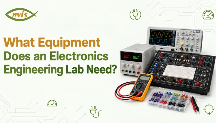
Experiments generally fall into two areas. Device characterization involves plotting a diode’s or transistor’s actual voltage-current characteristics against the expected textbook curves. This mainly requires a variable power supply, a multimeter, and the device being tested. Circuit level analysis, building a rectifier, amplifier, or wave shaping circuit and verifying its waveform or gain, needs an oscilloscope and function generator in addition. A lab equipped for only one of these teaches half the syllabus.
What Core Workbench Instruments Does Lab Need?
A variable DC regulated power supply is the starting point. Unlike a digital IC trainer kit’s fixed 5V rail, this lab needs an adjustable output, typically 0 to 30V with a current limit control, since experiments require biasing a transistor at a specific operating point or sweeping a diode across a voltage range. A dual-output supply, providing both positive and negative voltage rails, is useful for op amp experiments, particularly when using traditional devices such as the 741. These experiments commonly use symmetric supplies such as ±12V or ±15V, although the required voltage depends on the IC and circuit configuration. The current limit matters as much as voltage range, since a lab without it risks damaging a component every time a student wires a short circuit, a routine error in early sessions.
A digital multimeter capable of measuring DC and AC voltage, current, resistance, and ideally capacitance and diode forward voltage, is the most used instrument on a bench. It confirms a supply voltage, checks continuity on a suspected wiring fault, verifies a resistor’s actual value against its color code, and reads a transistor’s base emitter voltage during biasing. A lab should stock enough DMMs that no student group waits for one.
A breadboard, jumper wires in more than one color, and a stock of breadboard compatible resistors and capacitors are where the circuit gets built. Many introductory analog circuits can be assembled on breadboards because they require flexible component connections. However, some experiments may use dedicated trainer modules or other circuit assembly methods, depending on the experiment and its measurement requirements.
A soldering station, with a temperature controlled iron and adequate ventilation, becomes necessary once the syllabus includes any permanent assembly, such as a project board. Even where core experiments stay on breadboard, basic soldering skill is itself part of what this lab is meant to build.
What Test and Measurement Instruments Does Lab Need?
A dual trace cathode ray oscilloscope (CRO) or digital storage oscilloscope (DSO) is essential for observing a circuit’s actual output waveform rather than a single averaged reading. A multimeter can measure the rectifier’s output voltage, but an oscilloscope provides a visual representation of the waveform. It allows students to identify half-wave or full-wave rectification, observe the ripple remaining after filtering, and check whether a clipper is operating at the intended voltage level. Dual trace capability matters for comparing an amplifier’s input and output waveforms to measure gain and check for distortion.
A function generator produces sine, square, and triangular waveforms across a specified frequency range. It provides the controlled input signals required for circuit-level experiments, such as adjustable waveforms for clipper and clamper demonstrations and variable-frequency sine waves for measuring amplifier frequency response.
An LCR meter, measuring inductance, capacitance, and resistance directly, matters once the syllabus reaches filter design or frequency response work where actual component value, not its nominal marked value, needs to be known. It ranks below oscilloscope and function generator in priority for a basic first year lab.
Most electronics engineering lab syllabi close with a brief logic gate segment, so a logic probe and a small breadboard based logic setup round out test equipment. NvisTech’s guide to digital IC trainer kits covers fuller equipment a dedicated digital logic lab needs beyond this introductory segment.
Which Semiconductor Devices and Components Should Lab Stock?
For diode experiments, inventory needs general purpose silicon diodes such as 1N4001 through 1N4007 series for rectifiers and clipper clamper circuits, a small stock of Zener diodes for voltage regulation work, and an LED or two for forward bias demonstration. For transistor experiments, NPN and PNP BJTs, commonly BC547 and BC557 families, cover common emitter characteristic and amplifier work, and A suitable JFET, such as the BFW10 if specified in the laboratory syllabus, can be included for studying FET characteristics and comparing its behaviour with that of a BJT.
Op amp experiments require a general-purpose IC, commonly the 741, along with resistors and capacitors for building inverting amplifiers, non-inverting amplifiers, differentiators, and integrators. The 741 is a common choice for introductory experiments, although its supply voltage and operating limitations should be considered when designing the circuits. The logic gate segment needs only a small stock of basic gate ICs such as 7400 NAND, enough to demonstrate that NAND alone implements every other basic gate, without full IC range dedicated digital lab stocks.
A stock of resistors across standard values, ceramic and electrolytic capacitors, transformers for rectifier experiments, and connecting wire in multiple gauges completes the consumables list. Electrolytic capacitors need attention to polarity marking, since reversed polarity is the most common way this lab’s components get damaged.
What Trainer Kits and Modules Round Out Lab?
A basic electronics trainer kit, combining a regulated dual power supply and a breadboard area, sometimes with a built-in function generator or multimeter display, consolidates several workbench instruments into one unit and is increasingly common in newer labs. A linear IC trainer kit, built around op amps and other analog ICs rather than digital logic ICs, suits a syllabus where op amp experiments make up a significant share, since it typically provides dual supply rails and signal routing switches an op amp circuit needs more conveniently than a plain breadboard.
If the syllabus includes more than a basic introduction to logic gates, a compact digital logic trainer module can support the additional experiments without requiring the complete sequential logic equipment used in a dedicated digital electronics lab. An example is the NV6550 Digital IC Trainer. A department running a separate digital electronics lab in a later semester does not need to duplicate that fuller equipment here.
Worked Example: Oscilloscope Bandwidth and a Current Limiting Resistor
Oscilloscope bandwidth. A lab needs an oscilloscope to accurately display a 1 MHz square wave in a transistor switching experiment. A square wave’s fidelity on screen depends on how cleanly the scope displays its rise and fall edges, since the waveform is built from many odd harmonics of its fundamental frequency. For a 1 MHz square-wave experiment, oscilloscope bandwidth should be selected based on the required waveform fidelity and edge rise time. A common starting point is to choose an oscilloscope bandwidth at least five times the fundamental frequency for reasonable square-wave reproduction, although faster edges contain higher-frequency harmonics and may require greater bandwidth. A 20–25 MHz oscilloscope can be suitable for many introductory low-frequency experiments, but the actual requirement depends on the signal characteristics.
Current limiting resistor for an LED. A student connecting an LED to a 5V supply or logic output needs a series current-limiting resistor. For this example, assume the LED has a forward voltage of approximately 2V and a target operating current of 10 mA (0.01 A). These values should be verified against the LED datasheet and the output-current limits of the driving circuit. The resistor must drop the remaining voltage: V_R = 5V − 2V = 3V. Using Ohm’s law, R = V_R / I = 3V / 0.01A = 300 Ω. Since 300 Ω is not a standard E12 value, the nearest options are 270 Ω and 330 Ω. Choosing 330 Ω gives an operating current of approximately 9.1 mA, slightly below the assumed 10 mA target.
Both examples follow the same habit this lab is built to teach: start from a datasheet or known relationship, apply formulae, and choose real, available equipment or components with a reasonable margin.
What Experiments Does This Equipment Support?
The experiment sequence typically begins with component and instrument familiarization, covering resistor colour codes, capacitor markings, and the correct operation of a multimeter, power supply, oscilloscope, and function generator. Diode experiments follow, plotting a PN junction’s forward and reverse characteristic curve and building half wave and full wave rectifiers to measure ripple voltage with and without a filter capacitor. Clipper and clamper experiments use diodes with and without bias to shape a waveform, verified on an oscilloscope.
Transistor experiments cover BJT input and output characteristics in the common-emitter configuration, along with basic transistor biasing and amplifier experiments. Op amp experiments cover inverting, non inverting, differentiator, and integrator configurations using 741, each verified against its theoretical gain formula. The syllabus typically closes with a brief logic gate segment, realizing AND, OR, NOT, NAND, and NOR, often demonstrating that NAND alone implements every other gate, a bridge into fuller digital electronics lab syllabus that follows later.
device characterization experiments depend mainly on power supply and multimeter, with light demand on oscilloscope. Circuit level experiments, rectifiers, clippers, clampers, amplifiers, and op amp configurations, are where oscilloscopes and function generators earn their place, since verifying a waveform’s shape or gain requires observing signal rather than reading a single value.
How Should Lab Be Organized and Maintained?
Each workstation needs enough bench space for a power supply, an oscilloscope or shared access to one, a multimeter, a breadboard, and a component tray simultaneously, since breadboard wiring tends to use more visible connections than a digital trainer kit experiment. Components should be stored in labeled bins by value and part number, so a search for a specific resistor or transistor mid experiment does not cost lab time.
Electrical safety requires particular attention because bench instruments are connected to mains power, while variable DC supplies can provide voltages beyond the low-voltage levels commonly used in basic digital experiments. Standard precautions should be followed, including proper instrument earthing, switching off the power supply before changing circuit connections, and checking that electrolytic capacitors have discharged before handling them.
Maintenance is the piece most often neglected. Transistors and op amp ICs subjected to repeated breadboard insertion do fail with use, and a lab without a periodic device testing routine, using multimeter’s diode and transistor test functions, accumulates faulty parts scattered through component trays. Oscilloscopes and function generators need periodic calibration checks, since a drifted calibration produces a plausible but incorrect reading.
Electronics Engineering Labs in Indian Engineering Colleges
Indian engineering colleges and polytechnics run this lab, sometimes titled Basic Electronics Lab, Electronic Devices and Circuits Lab, or Analog Electronics Lab depending on university board, as a mandatory first year or second year practical for electronics, electrical, instrumentation, and computer science branches, following lab manuals aligned with AICTE model curricula. The sequence, from component familiarization and diode and transistor characteristics to op amp applications and a brief introduction to logic gates, is broadly consistent across institutions. However, the order of experiments and specific circuit configurations may differ between universities.
Practical examination format, wiring, powering, and measuring an assigned circuit within a fixed time and explaining it to an examiner, is why these equipment categories matter as a complete set. A student who has only studied theory is at a real disadvantage interpreting an actual oscilloscope trace under time pressure.
Does This Equipment Matter for GATE, SSC JE, and RRB JE Preparation?
The equipment itself is not directly examinable, but the concepts it demonstrates form part of the core subject matter across relevant engineering examination tracks. Electronic Devices and Circuits, covering diode characteristics, rectifiers, BJT and FET behavior, and op amp applications, is a core subject in GATE ECE and EE syllabi, and numerical questions on diode analysis, transistor biasing, or op amp gain mirror measurement process this lab teaches.
For RRB JE electronics and allied engineering categories, published technical syllabi include electronic devices, circuits, digital electronics, and linear integrated circuits. SSC JE primarily covers Civil, Electrical, and Mechanical engineering disciplines. Therefore, the relevance of electronics-specific topics depends on the selected discipline and the applicable examination syllabus. Technical interviews for electronics engineering roles may include questions about basic circuits, measurements, and semiconductor devices, depending on the organization and job requirements. Hands-on familiarity with diode, transistor, and op amp circuits can help candidates explain these concepts more confidently. Aspirants should verify the current year’s official syllabus notification from SSC and RRB before assuming any subject’s exact weightage, since exam patterns are revised periodically.
Basic Lab Setup vs a Well Equipped Lab
| Equipment Category | Basic Setup | Well Equipped Lab |
| Power supply | Single fixed voltage supply | Dual rail variable DC supply with current limiting |
| Core measurement | Analog multimeter only | Digital multimeter with diode and capacitance test modes |
| Signal instruments | None | Dual trace CRO or DSO, function generator |
| Semiconductor inventory | A few diodes and one transistor type | Diodes, Zener diodes, NPN and PNP BJTs, an FET, op amp ICs, basic gate ICs |
| Trainer support | Plain breadboard only | Basic electronics trainer kit with built in dual supply |
| Experiment coverage | Diode characteristics and simple rectifiers only | Full device characterization and circuit level syllabus, including op amp and logic gate segments |
A basic setup can still support diode characterization reasonably well. However, circuit-level experiments require additional instruments, particularly an oscilloscope and function generator, which are typically included in a well-equipped lab.
Setting Up or Upgrading Lab
A department setting up or upgrading this lab should start from its actual experiment list, then work backward to instrument specifications, component families, and trainer support, rather than starting from a generic equipment catalog. This lab and a dedicated digital electronics lab should be treated as separate equipment-planning decisions. Variable power supplies, oscilloscopes, and semiconductor components support diode, transistor, and op amp experiments, while comprehensive digital IC trainer kits and sequential logic components are better suited to a dedicated digital electronics lab.
These equipment categories should be considered together rather than as independent purchases. A lab with a good component inventory but inadequate test instruments may teach students to build circuits without properly verifying their behaviour. Similarly, a lab with capable instruments but limited components may not have the specific parts required for each week’s experiments.
FAQs
What is the difference between an electronics engineering lab and a digital electronics lab?
An electronics engineering lab is broader, typically a first year lab covering semiconductor devices, diode and transistor characteristics, rectifiers, and op amp circuits, with only a brief logic gate introduction. A digital electronics lab is a later, more specialized lab built around IC based digital logic, including flip flops, counters, and registers.
What is the single most important instrument in this lab?
There is no single most important instrument. The lab needs a variable power supply and multimeter for device characterization, and an oscilloscope with a function generator for circuit level waveform analysis. Missing either leaves a genuine gap in what students can measure.
Does the lab need an oscilloscope if it already has a multimeter?
Yes, for any circuit level experiment beyond device characterization. A multimeter gives a single averaged reading, while an oscilloscope shows waveform shape, timing, and distortion, which rectifier ripple, clipper clamper shaping, and amplifier gain experiments require to verify correctly.
What semiconductor devices should a first year electronics lab stock?
General purpose silicon diodes, a few Zener diodes, NPN and PNP BJTs, at least one FET for comparison, a general purpose op amp IC such as 741, and a small stock of basic logic gate ICs for the introductory digital segment.
How does this equipment connect to GATE or PSU interview preparation?
Indirectly but meaningfully. equipment itself is not examined, but concepts it demonstrates, diode and transistor characteristics, rectifier and amplifier behavior, and op amp applications, are core Electronic Devices and Circuits topics in GATE ECE and EE, and are frequently probed in PSU technical interviews.
Can a college run this lab and a digital electronics lab with the same equipment?
Only partially. A regulated power supply, multimeter, and oscilloscope serve both, but semiconductor inventory, breadboard based analog setup, and variable dual rail supply this lab needs are distinct from digital IC trainer kits and ZIF socket hardware a dedicated digital electronics lab requires.