


TL;DR –
- This blog is designed for electrical engineers, protection engineers, power system professionals, engineering students, and technical trainers who want to understand current and earth fault relay systems and techniques of coordination in depth.
- An overcurrent and earth fault relay protects electrical systems from overloads, short circuits, and ground faults by detecting abnormal current conditions and tripping breakers before damage occurs.
- Proper techniques of coordination ensure selective tripping, only the relay nearest to the fault operates, preventing unnecessary outages and maintaining system stability.
- Effective relay coordination involves data collection, fault current calculation, curve selection, pickup and time settings adjustment, TCC curve plotting, and thorough testing.
- Earth Fault Relay Testing Systems provide hands-on training to study relay characteristics, connections, and performance verification, helping students and professionals build practical protection expertise.
Modern power systems are designed to deliver electricity safely, reliably, and efficiently. However, electrical circuits are constantly exposed to disturbances such as short circuits, overloads, insulation failures, and ground faults. These faults, if not properly protected against, may cause equipment damage, fire hazards, and widespread outages.
At the core of electrical protection systems is the over current and earth fault relay, a fundamental device that monitors abnormal current conditions and isolates faulty sections before damage escalates.
Related Blogs –
- How Electricity Training Lab Can Become a Part of School-Level Skill Education
- Preparing Future Technicians and Engineers for Smart Energy Management
- What Is a Data Acquisition System and How Does It Work?
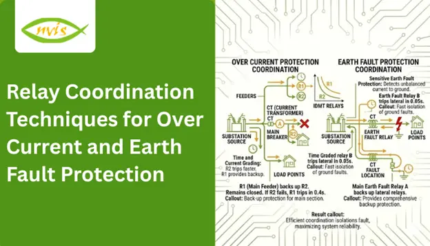
Over Current and Earth Fault Protection
Electrical systems operate within specified current limits. Protection devices must respond promptly whenever current exceeds normal limits due to faults or abnormal conditions.
Two of the most common fault types in power systems are:
- Over current faults – caused by overloads or short circuits
- Earth faults (ground faults) – caused when a conductor comes into contact with ground or grounded structures
The over current and earth fault relay offers protection in both scenarios. It measures current on a line using current transformers (CTs) and triggers breaker tripping upon meeting preset thresholds.
In multi-level distribution systems, relays are installed at feeders, transformers, busbars, and main incomers. If all relays trip simultaneously during a fault, the entire system may shut down unnecessarily.
This is where techniques of coordination become critical.
Earth Fault Relay Testing System
The Earth Fault Relay Testing System provides hands-on exposure to protection devices used to prevent faults caused by earth leakage currents. Effective protection is essential to ensure the safety and reliability of electrical systems.
Power systems make use of a number of protective devices, and studying how they work helps to use them in smarter ways and avoid system failures. Earth leakage current may cause excess heat and insulation degradation over time, and finally cause earth faults and sparking. An Earth Fault Relay senses leakage currents before they reach the preset threshold, thus safeguarding equipment and ensuring operational safety.
Nvis provides an interactive learning environment that demonstrates the connection of an Earth Fault Relay in a transmission line and allows testing of its operation. Through practical demonstrations using Nvis systems, students gain hands-on experience in the application and testing of Earth Fault Relays in power systems.
The Earth Fault Relay Testing System is an ideal educational platform for improving technical knowledge, practical training, and skill development among students and young professionals.
Product Features
- Inbuilt variable source
- Large-font LCD display for clear visibility
- Isolation transformer for safe operation
- Durable and rugged panel design
- Engineered with comprehensive safety considerations
- Diagrammatic representation for easy connections
Scope of Learning
- Study and verification of Earth Fault Relay operating characteristics under different plug settings
- Understanding the connection of an Earth Fault Relay in a transmission line
- Practical testing procedures of an Earth Fault Relay
Fundamentals of Over Current and Earth Fault Relays
Overcurrent protection operates when current exceeds a predefined pickup value. Overcurrent may result from:
- Overloads
- Phase-to-phase short circuits
- Three-phase faults
Overcurrent relays are classified into:
- Instantaneous Relays – operate with no intentional delay
- Definite Time Relays – operate after a fixed delay
- Inverse Time Relays – operating time decreases as fault current increases
Inverse time characteristics are widely used because they provide better discrimination.
What Are Earth Fault Relays?
Earth faults occur when current flows from phase conductors to ground due to insulation failure, cable damage, or equipment breakdown.
Earth fault protection is essential because:
- Ground faults may produce lower fault currents than phase faults
- They can cause severe damage if undetected
- Personnel safety is at risk
Earth fault relays are typically more sensitive and operate at lower pickup settings than phase overcurrent relays.
Combined Over Current and Earth Fault Relay
A modern over current and earth fault relay integrates both protection functions into a single numerical device. Benefits include:
- Reduced panel space
- Improved accuracy
- Multiple characteristic curve options
- Communication capability
- Event recording and fault analysis
Importance of Relay Coordination
Relay coordination ensures that only the protection device closest to the fault operates, while upstream devices remain active unless backup protection is required. When an over current and earth fault relay is properly coordinated, unnecessary power interruptions are avoided, and system stability is maintained.
Objectives of Coordination
- Selectivity – Isolate only the faulty section
- Reliability – Operate correctly during faults
- Speed – Clear faults quickly
- Sensitivity – Detect low-level fault currents
- Backup Protection – Provide redundancy if primary protection fails
Step-by-Step Relay Coordination
Systematic relay coordination study is critical in order to make sure that the over current and earth fault relay can work with an acceptable level of selectivity, reliability, and speed. Effective techniques of coordination follow a systematic engineering approach, as described below.
Step 1: Data Collection
The first step is collecting accurate system data. It comprises the single-line diagram (SLD), transformer ratings and impedance, cable sizes and lengths, CT ratios with accuracy class, and short-circuit levels available at different buses. Accurate data ensures reliable setting calculations and proper coordination.
Step 2: Fault Current Calculation
Then determine the anticipated fault currents in various system points. These are normally the three-phase faults, the line-to-line faults and the earth faults. Fault current values are used to set relay pickup settings and also assist in setting the time delays required in selective operation.
Step 3: Select Relay Characteristics
Select appropriate inverse time characteristics depending on the behavior and protection needs of a system. The most common are standard inverse, very inverse and extremely inverse curves. Selecting the correct curve is a critical aspect of relay coordination.
Step 4: Set Pickup Current
Relay pickup current is usually adjusted to between 125 and 150 percent of full load current. This prevents unnecessary tripping under normal conditions while ensuring reliable operation during fault conditions.
Step 5: Set Time Multiplier
Adjust the time multiplier (time dial setting) to maintain adequate coordination margin between downstream and upstream relays. This guarantees that the nearest relay will clear the fault first with the upstream devices acting as a backup.
Step 6: Plot TCC Curves
Time-Current Characteristic (TCC) curves are plotted using professional coordination software such as ETAP, DIgSILENT, or SKM. These plots help visually verify proper separation and coordination between relay curves.
Step 7: Verify and Test
Finally, verify the settings through secondary injection testing and commissioning validation. During testing, it is important to make sure that the over current and earth fault relay functions precisely as desired when the fault conditions are simulated.
Conclusion
Electrical protection is not merely about installing relays; it is about coordinating them to operate selectively and precisely. With a correctly implemented protection scheme, only the faulty part of the system is disconnected and the rest of the system keeps on functioning. Such performance is achieved only through systematic application of proven coordination techniques.
When properly coordinated, engineers achieve selective fault isolation, shield major equipment of thermal and mechanical harm, reduce expensive downtime, and enhance the general reliability of the system greatly. These advantages have vital roles in ensuring continuity of operation within industrial, commercial and utility power systems.
The over current and earth fault relay remains one of the most essential components of modern electrical protection systems. It offers reliable fault detection, quick clearance, and efficient backup protection when programmed using a thorough and systematic coordination examination. Relay coordination is not a luxury in modern power networks—whether in a manufacturing facility or a smart grid, it is a necessity for ensuring a robust and future-proof electrical system.
FAQs
An over current and earth fault relay is a protection device used in power systems to detect excessive current and ground (earth) faults. It monitors current through current transformers (CTs) and trips the circuit breaker when preset limits are exceeded, protecting equipment from damage.
Proper techniques of coordination ensure that only the relay closest to the fault operates first, while upstream relays act as backup. This prevents unnecessary outages and maintains system stability.
The key objectives include selectivity, reliability, speed, sensitivity, and backup protection. These ensure faults are cleared quickly without affecting healthy parts of the electrical system.
Overcurrent protection responds to excessive phase currents caused by overloads or short circuits, while earth fault protection detects leakage current flowing to ground due to insulation failure or conductor contact with earth.
TCC curves show the relationship between fault current magnitude and relay operating time. They are used in coordination studies to ensure proper separation between upstream and downstream relay settings.