







TL;DR
- This guide is written for engineering students, freshers, and GATE, SSC JE, and RRB JE aspirants who need a clear, exam ready understanding of two wattmeter methods for measuring power in three phase circuits.
- The two wattmeter method uses only two wattmeters, not three, to measure total power in a three phase system, regardless of whether load is balanced or unbalanced, star connected or delta connected.
- two core relationships are P = W1 + W2 for total power, andφ = tan⁻¹√3(W1−W2)/(W1+W2) for power factor angle in a balanced load.
- Wattmeter readings change character with power factor: both readings are equal at unity pf, one wattmeter reads zero at 0.5 lagging pf, and one wattmeter reads negative below 0.5 pf.
- This method remains a core skill for testing, commissioning, protection, and instrumentation engineers in India’s power sector in 2026, and it is distinct from consumer smart metering rollout under RDSS, which measures energy for billing rather than power for engineering analysis.
Also Read,
- How Lithium-Ion Batteries Work in Electric Vehicles: A Complete
- SOC and SOH in BMS: Understanding
- Speed Control of PMSM Motor: A Complete Beginner’s Guide
What Is a Two Wattmeter Method?
A wattmeter is an instrument that measures real power, also called active power, in an electrical circuit. It does this by combining two measurements at once: the current flowing through the circuit and the voltage across it. Internally, a wattmeter has two coils. The current coil is connected in series with the circuit, so the same current that flows through the load also flows through this coil. The pressure coil, also called the voltage coil, is connected in parallel across the circuit to sense voltage. A wattmeter’s needle or digital display indicates the product of these two quantities, adjusted for the phase angle between them, to show the actual power being consumed.The two wattmeter method is a standard technique used to measure the total active power in a three-phase, three-wire system using only two wattmeters instead of three. It works for both balanced and unbalanced loads, as well as for both star (Y) and delta (Δ) connected systems, making it one of the most widely used methods for three-phase power measurement in laboratories and industrial power systems.Why Three Phase Systems Need It?
In a single-phase circuit, one wattmeter is enough because there is only one phase to measure. A three-phase circuit is more complex because it has three separate phases, and in principle, each phase requires its own power measurement. In a three-phase, four-wire system with an accessible neutral conductor, three wattmeters connected between each phase and the neutral can directly measure the total power.Most industrial and power distribution systems, however, are three-phase, three-wire systems without an accessible neutral. In such systems, Blondel’s theorem states that the total power can be measured using one fewer wattmeter than the number of wires. Since a three-wire system has three conductors, only two wattmeters are required to measure the total active power accurately. This is the fundamental principle behind the two wattmeter method, allowing it to measure total power correctly for both balanced and unbalanced three-phase loads.Two Wattmeter Method Circuit Connection
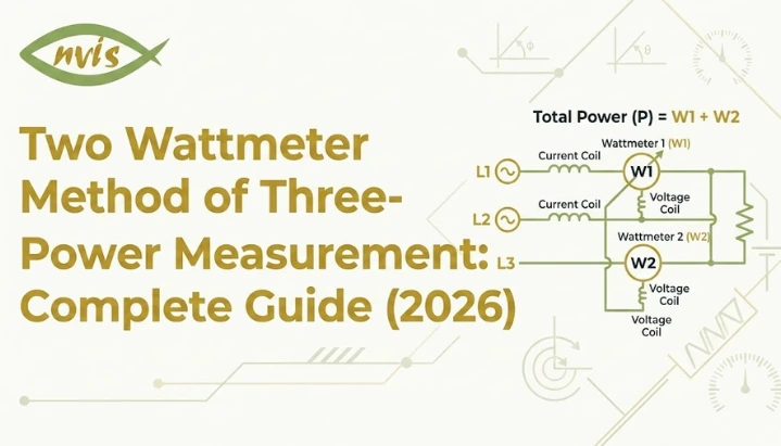
The physical connection of two wattmeters follows a consistent rule regardless of whether load is star connected or delta connected. Current coils of two wattmeters are connected in series with any two or three line conductors, commonly labelled R and Y, or A and B, depending on the naming convention used. No current coil is connected to the third line, commonly labelled B or C.Pressure coils of both wattmeters are then connected between the line carrying their respective current coil and the third, unmeasured line. In other words, one wattmeter’s pressure coil spans between line R and line B, while the other spans between line Y and line B. This means both pressure coils share a common connection point on the third line, even though no current coil is placed there.Star (Y) Connected Load
In a star connected system, the load’s three phases meet at a common neutral point, but this neutral point is typically not accessible or not used in a three wire supply. Two wattmeters are connected exactly as described above, with their current coils in two of three lines and their pressure coils referenced to the third line. The absence of a neutral connection does not affect the accuracy of the method, since two wattmeter methods are designed specifically to work without one.Delta (Δ) Connected Load
In a delta connected system, there is no neutral point at all, since each phase winding connects directly between two line conductors. The two wattmeter method applies here in exactly the same way as it does for a star connected load, because the method depends only on three line conductors, not on how the load’s internal windings are arranged. This is one of the practical advantages of the method: the same two wattmeter connection setup works whether the underlying load is star or delta connected, and the engineer performing the test does not need to know the internal configuration in advance.Two Wattmeter Method Formula and Derivation
Two wattmeter method formulas can be derived by analyzing a balanced three phase star connected inductive load. Consider a balanced system where phase voltage magnitude is V, line current magnitude is I, and load has a lagging power factor angle of φ between each phase voltage and its corresponding phase current.Each wattmeter measures the product of a line current, a line voltage, and cosine of angle between them. Using standard phasor analysis, current in wattmeter W1 lags its reference line voltage by an angle of (30° minus φ), while current in wattmeter W2 lags its reference line voltage by an angle of (30° plus φ). Since both wattmeters are referenced to line voltages of equal magnitude VL and carry line currents of equal magnitude IL in a balanced system, their individual readings work out to:W1 = VL IL cos(30° φ)W2 = VL IL cos(30° + φ)Adding these two expressions and simplifying using standard trigonometric identities produces a clean result. angle terms combine in such a way that sum equals:W1 + W2 = √3 VL IL cos φThis expression is exactly standard formula for total power in a balanced three phase system, confirming that sum of two wattmeter readings gives correct total active power, written as:P = W1 + W2The individual readings can also be used to extract power factor angle without needing to measure it separately. Subtracting two wattmeter expressions and dividing by their sum removes the VL IL term and leaves only trigonometric functions of φ. Working through this algebra gives power factor angle formula:φ = tan⁻¹ [√3 (W1 W2) / (W1 + W2)]Once φ is known, the power factor itself is simply cos φ. This derivation assumes a lagging power factor and a balanced load. For an unbalanced load, sum W1 + W2 still gives correct total power, but power factor angle formula above does not apply, since power factor is only a meaningful single value for a balanced three phase load.Two Wattmeter Method Numerical Example
A numerical example makes measurement of three phase power by two wattmeter methods easier to apply in practice. Consider a balanced three phase load connected to a 400 V line to line supply, drawing a total power of 10 kW at a lagging power factor of 0.8.The first step is to find the power factor angle. Since power factor is 0.8, φ = cos⁻¹(0.8), which works out to approximately 36.87°.The next step uses the power factor angle formula in reverse. Rearranging φ = tan⁻¹[√3(W1 W2)/(W1 + W2)] gives:tan φ = √3 (W1 − W2) / (W1 + W2)Since W1 + W2 = P = 10 kW, and tan(36.87°) is approximately 0.75, substituting these values gives:0.75 = √3 (W1 W2) / 10Solving this equation gives the difference between the wattmeter readings:W1 − W2 ≈ 4.33 kW.With two equations now available, W1 + W2 = 10 kW and W1 − W2 = 4.33 kW, solving simultaneously gives W1 = 7.165 kW and W2 = 2.835 kW.These two values represent what an engineer would actually observe on two wattmeter displays during a real test on this load. Adding them back together confirms total power of 10 kW, and the difference between them reflects the load’s lagging power factor of 0.8. This same step by step approach applies to any balanced three phase power measurement problem, and it is the method most frequently tested in GATE Electrical Engineering and SSC JE Electrical numerical questions.Wattmeter Readings at Different Power Factors
The relationship between two wattmeter readings and the load’s power factor is not linear, and it produces several distinct patterns that are important to recognize, both for practical testing and for exam preparation. The table below summarizes how readings behave across the power factor range for a balanced lagging load.| Power Factor | Angle φ | Wattmeter Behavior |
|---|---|---|
| Unity (1.0) | 0° | Both wattmeters read exactly equal values; each shows half total power. |
| Above 0.5 lagging | 0° to 60° | Both wattmeters read positive, but unequal, values; W1 reads higher than W2. |
| Exactly 0.5 lagging | 60° | One wattmeter (W2) reads exactly zero; the other reads full total power. |
| Below 0.5 lagging | 60° to 90° | lower reading wattmeter (W2) becomes negative; its terminals must be reversed to obtain a reading, and this value is then subtracted rather than added. |
| Zero (purely reactive) | 90° | Both wattmeters read equal and opposite values, and sum correctly shows zero real power. |
Applications of the Two Wattmeter Method
The two wattmeter method is widely used to measure total active power and power factor in three-phase, three-wire systems. Since it works for both balanced and unbalanced loads, it remains an important technique in electrical engineering.Some common applications include:- Testing and commissioning of transformers, motors, generators, and switchgear to verify power consumption against design specifications.
- Protection and metering for calibrating protective relays, revenue meters, and other power measurement equipment.
- Electrical engineering laboratories, where it is a standard experiment for studying three-phase power measurement and circuit analysis.
- Motor testing, particularly for evaluating the power drawn by three-phase induction motors and synchronous machines under different operating conditions.
- Renewable energy and EV charging systems, where similar measurement principles are used in digital instrumentation to verify power flow and power factor.
Limitations and Practical Precautions
While the two wattmeter method is accurate and widely used, a few practical limitations should be considered during testing.- Instrument transformer errors: Current transformers (CTs) and potential transformers (PTs) can introduce small phase-shift errors, especially at low power factors, affecting wattmeter accuracy.
- Correct connections are essential: The current and pressure coils must be connected with the correct polarity. Incorrect connections can result in wrong or negative wattmeter readings.
- Cannot identify leading or lagging power factor: The method calculates the magnitude of the power factor angle but cannot determine whether the load is leading or lagging without additional information.
- Proper instrument ratings: Wattmeters and CTs should be rated for the expected line current and voltage to ensure accurate measurements and prevent instrument damage. Standard electrical safety practices should always be followed when working on live three-phase circuits.
Future of the Two Wattmeter Method
The classical electrodynamometer wattmeter, with its analog needle display, has largely been succeeded in modern testing environments by digital and microprocessor based power analyzers. Instruments in this category, produced by manufacturers such as Yokogawa and others, apply the same underlying two wattmeter mathematical principle internally, but they compute readings digitally rather than through a mechanical mechanism. These digital instruments offer several practical advantages, including automatic compensation for phase errors introduced by current and potential transformers, real time display of individual phase power alongside total power and power factor, harmonic analysis capability, and built in data logging with communication interfaces such as Modbus and Ethernet for integration into larger monitoring systems.This shift toward digital instrumentation does not change underlying physics or mathematics covered in this guide. Whether an engineer is reading an analog wattmeter dial in a college laboratory or interpreting a digital display on a modern power analyzer during a substation commissioning test, two wattmeter principles, formula P = W1 + W2, and power factor relationship derived from two readings remain exactly the same. Understanding classical methods thoroughly is what allows an engineer to correctly interpret, troubleshoot, and validate output of any modern digital instrument built on the same foundation.At same time, India’s power sector is undergoing significant modernization on the metering side, driven by RDSS smart meter rollout and CEA’s 2026 regulatory push toward mandatory smart metering for consumers. This transformation is reshaping how electricity is billed and monitored at consumer level, but it operates alongside, rather than in place of, engineering side power measurement skills covered in this guide. For students entering the workforce, familiarity with both classical two wattmeter methods and digital instrumentation that has grown from it provides a stronger technical foundation for roles across testing, commissioning, protection, and instrumentation engineering.Conclusion
The two wattmeter method remains one of the most fundamental techniques in three phase power measurement, valued for its ability to determine total active power and power factor in balanced or unbalanced, star or delta connected loads using just two instruments instead of three. Its derivation rests on straightforward phasor analysis, its formula P = W1 + W2 is simple to apply once underlying connection is understood, and its special case behavior at different power factors, including zero reading case at 0.5 lagging pf and negative reading case below it, follows predictable and learnable patterns rather than being arbitrary exceptions. For engineering students in India, mastering this method serves a dual purpose: it builds conceptual foundations tested repeatedly in GATE, SSC JE, and RRB JE examinations, and it develops a practical skill directly applicable to testing, commissioning, protection, and instrumentation roles across the power sector. As India’s power infrastructure continues to modernize through initiatives such as RDSS smart meter rollout and evolving CEA regulations, underlying measurement principle behind two wattmeter method continues to operate quietly within digital power analyzers now used across industry, making it a technique worth understanding thoroughly rather than memorizing for a single exam.FAQs
The two wattmeter method is a technique used in electrical engineering to measure total active power in a three phase, three wire system using only two wattmeters. It works for both balanced and unbalanced loads and for both star and delta connected systems, with total power given by sum of two wattmeter readings.
The two -wattmeter method formula for total power is P = W1 + W2. For a balanced load, power factor angle can be calculated using φ = tan⁻¹√3(W1−W2)/(W1+W2) after which power factor itself is obtained as cos φ.
The sum of two wattmeter readings gives correct total power regardless of whether load is balanced or unbalanced. power factor angle formula, however, applies only to balanced loads, since power factor is not a single defined value for an unbalanced three phase load.
The formula used to calculate power factor angle produces the same magnitude of φ whether load is leading or lagging, since it depends only on the difference between two wattmeter readings rather than direction of phase shift. Determining whether power factor is leading or lagging requires additional information about load or an auxiliary measurement.
At exactly 0.5 lagging power factor, one of two wattmeters reads exactly zero while the other reads full total power. Below 0.5 lagging power factor, lower reading wattmeter reads a negative value, which must be subtracted rather than added when calculating total power.
Yes. India’s RDSS smart meter rollout and CEA’s 2026 metering regulations concern consumer energy billing, which is a separate function from engineering power measurement. The two -watt meter method remains the underlying principle used in testing, commissioning, protection calibration, and even in digital power analyzers that have replaced older analog wattmeters in modern power system work.