





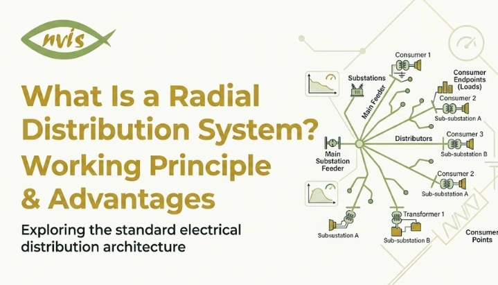
TL;DR
- This blog is for engineering students, freshers, and anyone new to power systems who wants to understand how electricity actually travels from a substation to their home, explained in plain English before technical terms show up.
- A radial distribution system sends power in one direction only, like a tree with a single trunk and branches, which makes it simple and cheap but leaves everyone downstream vulnerable if something breaks upstream.
- You will learn exactly how a radial system is built, why it still powers most of rural and small town India despite being over a century old as a design, and where it genuinely struggles.
- We will also break down the ring main system, which fixes the radial system’s biggest weakness by giving power a second path to travel, and compare both side by side.
- By the end, you will understand not just definitions but actual engineering logic behind why utilities choose one system over another, plus where 2026’s smart grid technology is changing that choice.
A single garden hose connected to one tap illustrates the basic idea well. Water flows from tap, through hose, and outward to wherever it is directed. If that hose has smaller hoses branching off it, each watering a different flower bed, stepping on the main hose near the tap stops every branch downstream from receiving water immediately. Nothing resumes until that one blockage is cleared.
A radial distribution system works on essentially the same principle, except substance moving through the network is electricity, and the area being served is an entire town, industrial zone, or residential colony rather than a garden.
This design is one of oldest and most widely used methods of delivering electricity from a substation to homes and businesses. It is neither the most sophisticated nor most reliable system available, yet it has remained in use for over a century because it solves a specific practical problem effectively: distributing power to a large number of consumers at low cost and with minimal complexity.
This guide covers what a radial distribution system is, how it functions step by step, why it continues to be widely adopted, where its limitations lie, and how the ring main system was developed to address its central weakness. It also examines how rooftop solar adoption and smart grid automation are reshaping distribution design in 2026.
Also Read,
- What is a PMSM Motor? Full Form, Working
- What is a BLDC Motor? Full Form, Working
- Solar EV Charging Station Concepts Explained: How It Works
Understanding Power Distribution Before We Get Into Radial Systems
Before we zoom into the radial system specifically, it helps to understand the bigger picture it fits into.
Electricity does not travel directly from a power plant to your ceiling fan. It goes through a long relay race. Power plants generate electricity at very high voltages because that is the most efficient way to push electricity across long distances with minimal loss. This high voltage electricity travels through transmission lines, massive steel towers you see crossing highways and open fields, until it reaches a substation closer to where people actually live.
At substation, transformers step that voltage down to a level that is safer and more usable. From here, jobs shift to the distribution system, network of wires, poles, and transformers that carries electricity to homes, shops, and factories.
There are a few different ways engineers design this final stretch, and the layout they choose is called distribution topology. A radial system is one option. The ring main system is another. There is also an interconnected system, which is essentially a ring main powered by more than one substation. Each has its own tradeoffs around cost, reliability, and complexity, and understanding radial systems is really the foundation for understanding all of them.
What Is a Radial Distribution System
Now let us get specific. A radial distribution system is a layout where power flows from a single substation, out through feeder lines, and finally to individual consumers, with electricity moving in only one direction the entire time. There is no loop, no alternate path, and no second route for power to take if the main one gets blocked.
Go back to that garden hose picture. tap is your substation. The main hose is your primary feeder, thick cable that carries the bulk of electrical load. smaller branching hoses are lateral, secondary lines that peel off main feeder to serve specific streets, buildings, or neighborhoods. Water, or in this case current, only moves outward from the tap. It never flows back or sideways to find another route.
This is why the system is called “radial.” Think of a bicycle wheel. spokes radiate outward from the center hub in straight lines, each one independent of others. A radial distribution system radiates out from its substation in exactly the same way, with each feeder acting like its own spoke, unconnected to others.
How a Radial Distribution System Actually Works
Here is where pieces come together. A radial distribution system is built from four main components, and each one plays a distinct role in getting power from substation to your switchboard.
substation is the starting point. This is where high voltage electricity coming in from the transmission network gets stepped down to distribution level voltage by transformers. Think of this as a pressure regulator on our garden hose, it takes something too powerful to use directly and brings it down to a manageable level.
From substation, primary feeders carry this power outward. These are thick, high capacity lines designed to handle a large chunk of total electrical load, similar to that main garden hose carrying bulk of water flow.
Laterals branch off primary feeders to serve smaller, localized areas, a specific street, a housing block, or a single large building. This is where branching hoses come in, each one dedicated to a smaller piece of overall coverage area.
Finally, distribution transformers step voltage down one more time, from feeder level voltage to actual usable voltage that reaches your home’s wiring, typically 230V single phase or 415V three phase supply used across most of India.
Now here is the part that really defines a radial system: what happens when something goes wrong. Since power only flows in one direction, a fault, say a fallen tree branch snapping a line, anywhere along a feeder cuts off electricity to every single consumer downstream of that point. There is no rerouting, no backup path, no way for power to reach those consumers through a different route. Everyone past fault simply loses supply until repair crews physically fix the break.
This single direction, no backup design is both the radial system’s greatest strength and its biggest limitation, and understanding why requires looking at both sides.
Why Radial Distribution Systems Are Still So Widely Used
If losing power to an entire neighborhood because of one broken line sounds like a serious drawback, you might wonder why anyone still builds systems this way. The answer comes down to one word: economics.
A radial system is, hands down, the cheapest and simplest distribution layout to design, build, and maintain. It needs fewer cables, fewer switches, and far less protective equipment compared to more complex layouts. There is no loop to close, no need for sophisticated switching logic to figure out which direction power should flow. Engineers can plan and lay out a radial network relatively quickly, which matters enormously when you are trying to electrify a large rural area or a rapidly growing township without unlimited budget.
This is exactly why radial systems dominate in a few specific situations. Rural electrification is a classic case. In villages and small towns with lower population density and spread out homes, spending extra money on backup pathways rarely makes financial sense when an alternative, a simple radial line, gets the job done at a fraction of cost.
You will also find radial systems in peripheral urban and suburban feeders, edges of cities where load is scattered and reliability requirements are lower than in a dense city center. Individual industrial plants often use radial layouts internally for specific process areas or lighting circuits, where a brief outage is inconvenient but not catastrophic. And for temporary power supplies, like construction sites or mining operations, radial systems are almost always the default choice because mobility and speed of setup matter more than long term reliability.
Put simply, radial layouts still dominate distribution at voltages below 33kV, particularly for medium density residential areas, small commercial zones, and process load centers, because simplicity to cost ratio is hard to beat when uninterrupted supply is not top priority.
Real Limitations of a Radial Distribution System
Simplicity always comes with tradeoffs, and it is worth being honest about what those are before deciding whether a radial system fits your situation.
The most obvious weakness is low reliability. Because there is no alternative feeder or backup path, any fault anywhere along the line results in a complete supply failure for every consumer positioned after that fault point. If you live at the far end of a radial feeder and someone else’s transformer trips near the substation, your lights go out too, even though the problem has nothing to do with your part of the network.
There is also a voltage drop problem built into the physics of the system. As electricity travels further from substation, some voltage is inevitably lost along the way due to resistance in wires. This means consumers closer to the substation get a healthy, stable voltage, while those at the far end of a long feeder often experience noticeably lower voltage, especially during peak demand hours. Utility engineers have to size conductors carefully and place transformers strategically just to keep this voltage drop within acceptable limits.
Uneven loading is another consequence of layout. The section of distributor closest to the substation ends up carrying the heaviest current load, since it has to support everything downstream of it. This uneven distribution of electrical stress across networks is simply built into how radial systems are structured.
Finally, fault location can be genuinely difficult to pinpoint. When something goes wrong deep inside a sprawling radial network, technicians often have to physically trace line section by section to find exact break, which can mean longer outage times compared to systems with built in monitoring and isolation features.
None of these limitations make radial systems a bad choice. They simply define where the system makes sense and where it does not. And that brings us to a design that was created specifically to solve reliability problems.
Radial System vs Ring Main System: What Changes
If you take everything we just covered about radial systems and ask, “what if we gave power a second way to reach the same point,” you arrive at the ring main system.
A ring main distribution system is a closed loop configuration where the feeder starts at a substation, loops through the entire service area, and comes back to the same substation, forming a complete circle rather than a straight line with branches. Every distribution transformer along this loop is connected to two feeder paths instead of one.
Think back to our garden hose analogy, but now imagine the hose is a full circle instead of a single line with branches. Water can reach any point on that loop from two different directions. If you pinch the hose at one spot, water simply reroutes and flows to that same spot from another direction. Nothing downstream loses supply.
This is precisely what the ring main system achieves electrically. If a fault occurs anywhere along the ring, switchgear isolates just that faulty section, and every other consumer on loop continues receiving power from the opposite direction. This single design change fundamentally transforms the reliability equation.
How Ring Main System Works
mechanics of a ring main system are not dramatically different from a radial one at component level, transformers, feeders, and distribution equipment are all still present. What changes is topology, the way these components are connected together.
loop begins and ends at the same substation bus bar. Distribution transformers are tapped at various points around this loop rather than sitting at the end of a dead end branch. Ring Main Units (RMUs) are compact switchgear installed at tap-off points. Working together with protective relays and circuit breakers, they isolate faulty sections while keeping the remaining network energized.
When a fault occurs somewhere on a ring, protective devices like circuit breakers and relays detect exactly where the problem is and isolate only that specific segment. Power continues flowing to every other consumer through the opposite side of the loop. Once repair crews fix faulty sections, it gets reconnected, and the ring returns to its normal closed loop state.
This closed loop structure also solves voltage drop and uneven loading problems that plague radial systems. Since every point on the ring can potentially receive power from two directions, electrical loading can be shared between two supply paths, depending on the network configuration and operating conditions. Voltage fluctuations at any given consumer’s terminal are also significantly reduced, because power is essentially arriving from both sides rather than weakening steadily along one long single direction line.
Radial vs Ring Main: A Direct Comparison
| Factor | Radial Distribution System | Ring Main Distribution System |
| Power flow direction | Single direction only | Can flow from either direction |
| Initial cost | Low | Higher, due to extra cable and switchgear |
| Reliability | Low, one fault cuts supply to everyone downstream | High, faults are isolated without a full outage |
| Voltage drop | Significant at far end of long feeders | Minimal, load is balanced across loop |
| Maintenance | Requires full shutdown of affected section | Sections can be isolated while rest stays powered |
| Fault location | Harder to trace, longer repair time | Easier to isolate using RMUs and protective relays |
| Best suited for | Rural areas, small towns, temporary supply, low density zones | Cities, hospitals, industrial parks, data centers, anywhere continuous power matters |
Neither system is universally “better.” The right choice depends entirely on what specific area needs. A rural stretch with scattered homes rarely justifies extra cost of a ring main. A hospital or a data center, on other hand, cannot afford the kind of prolonged outage a radial fault would cause, making ring main’s higher upfront cost an easy trade to accept.
Radial Distribution Systems in Age of Smart Grids
Here is something worth understanding as you head into 2026 and beyond: the way engineers think about radial systems is shifting, even if underlying wiring often stays the same.
Two big forces are reshaping distribution design right now. First is distributed generation, a term that basically means power sources that are not traditional centralized power plants. Rooftop solar panels, small battery storage systems, and even electric vehicles feeding power back into the grid are becoming common, especially as adoption accelerates across Indian households and businesses. A traditional radial system was designed around the assumption that power flows in exactly one direction, from substation to consumer. When a home with rooftop solar starts pushing power back into the grid during sunny hours, that one directional assumption starts to break down, and utilities have to rethink how their radial feeders handle this reverse flow.
The second force is grid automation, and this one is a genuinely exciting shift. Distribution networks in 2026 are increasingly using sensors, real-time monitoring, and automated switching to detect faults, isolate the affected section, and restore supply to healthy sections within seconds where feeder automation is available, often before a technician is even dispatched. This is sometimes called a self-healing grid. Even within a fundamentally radial layout, adding automated sectionalizing switches, tie switches, and remote monitoring can dramatically cut outage times, closing some of the reliability gap that traditionally only a ring main system could offer.
None of this means radial systems are disappearing. For low density rural areas and temporary installations, core economics still favor a simple radial layout. What is changing is the layer of intelligence sitting on top of that layout, using data and automation to make even a basic radial network respond faster and smarter when something goes wrong.
Conclusion
A radial distribution system is, at its core, a straightforward idea: send power outward from a single source, branch by branch, in one direction. That simplicity is exactly why it has powered rural electrification, small towns, and temporary installations for over a century, and why it remains practical, budget friendly choice wherever high reliability is not top priority.
But that same simplicity is also its biggest weakness. A single fault anywhere along a line can cut power to everyone downstream, voltage naturally drops the further you travel from substation, and locating faults can take time. The ring main system exists precisely to solve this problem, giving power a second path so that a fault in one section does not mean an outage for everyone else on the network.
As you continue exploring electrical engineering, whether for coursework, competitive exams like GATE or SSC JE, or genuine curiosity about how grid around you actually works, understanding radial and ring main systems gives you a solid foundation for grasping more advanced topics like interconnected systems, smart grid automation, and growing role of distributed generation in reshaping how power reaches our homes.
FAQs
A radial distribution system sends power in a single direction from substation to consumers with no backup path, while a ring main distribution system forms a closed loop, allowing power to reach any point from two directions and continue supplying consumers even if one section develops a fault.
It remains widely used because it is significantly cheaper to install and simpler to maintain than alternatives like ring main systems, making it a practical choice for rural areas, small towns, and temporary power supplies where high reliability is not the primary concern.
Since power flows in only one direction with no alternate route, a fault anywhere along the feeder cuts off supply to every consumer positioned downstream of that fault point until repair crews physically locate and fix the break.
Not necessarily. A ring main system offers much higher reliability and better voltage stability, but it also costs significantly more to install due to extra cabling and switchgear required, so radial systems are still a more economical choice for low density or budget constrained areas.
A Ring Main Unit (RMU) is a compact switchgear unit used in ring main distribution systems. It works with protective devices to isolate faulty sections while allowing the rest of the loop to remain energized, minimizing power interruptions to unaffected consumers.
Modern grid automation is adding sensors and automated switching to radial networks, allowing faults to be detected and isolated within seconds rather than requiring a technician to manually trace lines, which is narrowing the reliability gap between radial and ring main systems even without a full topology change.