





TL;DR
- The purpose of this article is to help engineering and diploma level candidates such as those preparing for GATE, SSC JE and RRB JE exams by providing them an easy-to-understand explanation about half-subtraction problems and their solutions rather than merely memorizing formulas from textbooks.
- The half subtractor performs single-bit subtraction using two inputs, A and B, without a borrow-in. The full subtractor takes three inputs A, B, and borrow-in to perform single-bit subtraction while accounting for a borrow from the previous bit position. Full subtractors can be chained to perform multi-bit subtraction.
- XOR, AND, OR AND NOT gates are used to build both of these circuits; A full subtractor can also be built by connecting two half-subtractors with an additional OR gate.
- The difference output is D = A ⊕ B ⊕ Bin, while the borrow-out equation is Bout = A’B + A’Bin + BBin.
- In many modern processor designs, subtraction is implemented using the same adder hardware by adding the 2’s complement of the subtrahend rather than using a completely separate subtractor chain.
Subtractors are combinational circuits for performing binary subtraction through logic gate operations. There are two types of digital circuits used by computers – an half-subtractor that subtracts two individual binary digits at once, and a full-subtractor where it subtracts two bits but takes into account any borrows received during its operation.
Binary subtraction is used for comparison, decrementing or computing differences between numbers by an ALU within processor architecture as well as simple calculators. Digital electronics students often encounter half-subtractor and full-subtractor problems at some point during their studies; these come up shortly after learning half-adder and full adder units since they both have similar designs that are commonly tested on tests papers or laboratory assignments.
The article explains the basics of binary subtraction, including how to derive truth tables, Boolean expressions, and gate-level circuits for half and full subtractors, how we derive truth table values through logic gates operation, how boolean expressions come out of these operations, and finally about designing circuitry at the gate level. Also it includes an example of working multi-bit subtraction which shows how such circuitry is implemented on chips rather than being available as separate components for use by microprocessors.
Also Read,
- Arduino for Embedded Systems Learning: Setting Up Your First Lab Project
- IoT Microcontroller Projects for Engineering Students: From Sensor to Cloud
- ARM Cortex M Microcontrollers Explained: Architecture for Embedded Engineering Students
What Do You Need to Know Before Learning Subtractors?
The subtractive circuit is based on knowledge about binary digits, borrowing during subtraction operations, and simple logic gate circuits. A brief overview of each would be useful to read about before going into detail on circuitry itself.
Binary subtraction is performed similarly to decimal subtraction by processing each digit individually starting from LSB then MSB. If a smaller value is subtracted by another bigger value then we need to borrow from an adjacent digit like how you do when doing decimal subtraction. For instance, subtracting 1 from 0 in a single binary column isn’t possible without borrowing; hence it would be written as 1 with a borrow of 1 taken from the next column.
The borrowing process explains why there are two types of subtraction circuitry. The half-subtractor produces an output value but does not receive any input values since its purpose is just to generate a borrow at the least significant position during subtraction when no borrowing occurs beforehand. A full subtractor can receive a borrow from the previous bit position and may generate a new borrow for the next higher bit. It’s similar to this as there are similarities between a half-adder and an adder; so if you’re familiar with them then it’ll be easier for you to understand subtraction circuits from those sources of knowledge.
The gates involved are same basic building blocks used throughout combinational logic design: The gates involved are basic building blocks used throughout combinational logic: an XOR gate produces 1 when its inputs differ, an AND gate produces 1 only when both inputs are 1, an OR gate produces 1 when at least one input is 1, and a NOT gate inverts its input. These gates are the basic building blocks used to implement half and full subtractor circuits.
How Does a Half Subtractor Work?
A half subtractor is a combinational circuit that subtracts one single bit binary number (B, subtrahend) from another (A, minuend) and produces two outputs: Difference (D) and Borrow (Bo). It has exactly two inputs and no borrow in, which is what makes it a “half” circuit rather than a full one.
The operation being performed is A − B, where A and B are each a single bit. There are four possible input combinations, and working through each one by hand builds the truth table directly.
When A = 0 and B = 0, subtraction is 0 − 0, giving a difference of 0 with no borrow needed. When A = 0 and B = 1, subtraction is 0 − 1, which cannot be done directly in a single bit; a borrow is taken from the next higher bit, and the difference becomes 1 with borrow = 1. When A = 1 and B = 0, subtraction is 1 − 0, giving a difference of 1 with no borrow. When A = 1 and B = 1, subtraction is 1 − 1, giving a difference of 0 with no borrow.
Half Subtractor Truth Table
| A | B | Difference (D) | Borrow (Bo) |
| 0 | 0 | 0 | 0 |
| 0 | 1 | 1 | 1 |
| 1 | 0 | 1 | 0 |
| 1 | 1 | 0 | 0 |
Reading the Difference column against inputs, D is 1 exactly when A and B differ, which is the definition of XOR operation. Reading the Borrow column, Bo is 1 only in a single row where A = 0 and B = 1, which corresponds to A being 0 while B is 1, written as A’ AND B.
Half Subtractor Equations
Difference: D = A ⊕ B
Borrow: Bo = A’B
These two expressions are already in their simplest form; no further Boolean simplification (through Karnaugh maps or otherwise) is needed, since each expression covers exactly one product term or a single XOR relationship.
How Do You Build a Half Subtractor Circuit?
The gate level circuit follows directly from two equations. Difference output needs a single two input XOR gate, fed by A and B. Borrow output needs A to be inverted first (using a NOT gate) and then ANDed with B, so this branch uses one NOT gate and one two input AND gate.
In total, a half subtractor requires one XOR gate, one AND gate and one NOT gate, three gates in all, with A and B feeding both branches in parallel. Both outputs are produced directly from inputs with no intermediate feedback, which is what makes this a combinational circuit rather than a sequential one: outputs depend only on present input values, not on any stored state.
Why Do You Need a Full Subtractor?
A half subtractor works fine for a single bit, but real subtraction problems involve multi bit numbers, and every column after least significant bit may need to account for a borrow taken by the column before it. A half subtractor has no input for that incoming borrow, so it cannot be reused directly for second, third or any higher order bit of a multi bit subtraction.
A full subtractor solves this by adding a third input, Borrow in (Bin), alongside A and B. It produces the same two outputs as before, Difference (D) and Borrow out (Bout), but now both outputs are calculated using all three inputs. This is exactly the same problem a full adder solves for addition, where a Carry in input lets adder stages be chained together for multi bit arithmetic.
How Does a Full Subtractor Work?
With three inputs, a full subtractor truth table has eight rows instead of four. Each row represents subtraction A − B − Bin performed as a single bit operation, with the result expressed as a difference bit and a borrow out bit.
Full Subtractor Truth Table
| A | B | Bin | Difference (D) | Borrow out (Bout) |
| 0 | 0 | 0 | 0 | 0 |
| 0 | 0 | 1 | 1 | 1 |
| 0 | 1 | 0 | 1 | 1 |
| 0 | 1 | 1 | 0 | 1 |
| 1 | 0 | 0 | 1 | 0 |
| 1 | 0 | 1 | 0 | 0 |
| 1 | 1 | 0 | 0 | 0 |
| 1 | 1 | 1 | 1 | 1 |
Each row can be checked by working through A − B − Bin directly. For instance, in the second row, A = 0, B = 0 and Bin = 1, so operation is 0 − 0 − 1, which needs a borrow, giving D = 1 and Bout = 1. In the fourth row, A = 0, B = 1 and Bin = 1, so the operation is 0 − 1 − 1. The result requires a borrow, giving a difference bit of 0 and a borrow-out of 1.
Full Subtractor Equations
Difference output follows same three variable XOR pattern seen in a full adder’s sum output:
D = A ⊕ B ⊕ Bin
Borrow out output is derived by grouping truth table rows where Bout = 1 (rows 2, 3, 4 and 8) using a Karnaugh map. simplified result is:
Bout = A’B + A’Bin + BBin
This expression can be read as: a borrow is generated if A is 0 and B is 1 (a direct borrow, same as half subtractor case), or if A is 0 and a borrow already came in, or if B and Bin are both 1 (meaning subtrahend and incoming borrow together exceed what A alone can supply). Each term corresponds to one physical reason a borrow becomes necessary at that bit position.
How Do You Build a Full Subtractor Using Two Half Subtractors?
A full subtractor can be built either directly from its two equations using individual gates, or, more commonly in textbooks and lab exercises, by combining two half subtractors with one additional OR gate. Both approaches produce the same truth table; the two half subtractor version is worth understanding because it shows how a complex combinational circuit can be built from a simpler, already understood building block, a pattern that repeats throughout digital design.
construction works in three steps. First, A and B are fed into first half subtractor, producing an intermediate difference (A ⊕ B) and an intermediate borrow (A’B). Second, this intermediate difference and Bin are fed into a second half subtractor, producing final Difference output (A ⊕ B ⊕ Bin, matching equation derived earlier) and a second intermediate borrow, which is (A ⊕ B)’Bin. Third, two intermediate borrow outputs, from first and second half subtractors, are combined with an OR gate to produce final Bout.
It is worth confirming that this construction actually reproduces the Bout equation derived earlier from Karnaugh map. Expanding (A ⊕ B)’Bin and OR ing it with A’B algebraically simplifies to A’B + A’Bin + BBin, same expression obtained directly from truth table. This confirms both derivation paths agree, which is a useful check to perform by hand when studying this circuit for an exam, since it builds confidence in Boolean simplification rather than relying on memorized results.
A full subtractor can be implemented with seven basic gates using the simplified equations: two XOR gates, three AND gates, one NOT gate and one OR gate. Using two standard half-subtractor blocks plus an OR gate also results in seven gates when the gates inside each half subtractor are counted.
Worked Example: Subtracting Two 4 Bit Binary Numbers
A single full subtractor handles one bit. Multi bit subtraction is done by chaining full subtractors together, with Borrow out of each stage connected to Borrow in the next higher stage, and least significant stage typically implemented as a half subtractor (or a full subtractor with Bin permanently tied to 0).
Consider subtracting B = 0110 (decimal 6) from A = 1011 (decimal 11), a calculation in style commonly seen in GATE and SSC JE digital electronics questions.
Bit 0 (LSB): A0 = 1, B0 = 0, Bin = 0 (no incoming borrow at first stage). D0 = 1 ⊕ 0 ⊕ 0 = 1. Bout0 = A0’B0 + A0’Bin + B0·Bin = 0 + 0 + 0 = 0.
Bit 1: A1 = 1, B1 = 1, Bin = Bout0 = 0. D1 = 1 ⊕ 1 ⊕ 0 = 0. Bout1 = A1’B1 + A1’Bin + B1·Bin = 0 + 0 + 0 = 0.
Bit 2: A2 = 0, B2 = 1, Bin = Bout1 = 0. D2 = 0 ⊕ 1 ⊕ 0 = 1. Bout2 = A2’B2 + A2’Bin + B2·Bin = (1)(1) + (1)(0) + (1)(0) = 1.
Bit 3 (MSB): A3 = 1, B3 = 0, Bin = Bout2 = 1. D3 = 1 ⊕ 0 ⊕ 1 = 0. Bout3 = A3’B3 + A3’Bin + B3·Bin = 0 + 0 + 0 = 0.
Reading different bits from MSB to LSB gives D3 D2 D1 D0 = 0101, which is decimal 5. This matches the expected result directly: 11 − 6 = 5. final Bout3 = 0 confirms that no borrow was needed beyond the most significant bit, which is expected since A (11) is larger than B (6) and subtraction does not go negative.
If A had been smaller than B, final borrow out would come out as 1, signaling that true result is negative and that difference bits represent 2’s complement of actual magnitude, a detail that matters when interpreting subtractor output in signed number systems.
Half Subtractor vs Full Subtractor: What’s Difference?
| Aspect | Half Subtractor | Full Subtractor |
| Inputs | 2 (A, B) | 3 (A, B, Bin) |
| Outputs | 2 (D, Bo) | 2 (D, Bout) |
| Borrow in handling | Not accepted | Accepted and used in both outputs |
| Difference equation | A ⊕ B | A ⊕ B ⊕ Bin |
| Borrow equation | A’B | A’B + A’Bin + BBin |
| Gate count (direct implementation) | 3 (XOR, AND, NOT) | 5 (2 XOR, 2 AND, 1 OR) or 7 using two half subtractors |
| Used for | LSB of a multi bit subtraction only | Every bit position after LSB |
| Cascadable | No | Yes |
Where Are Subtractors Used in Real Circuits?
Subtractor circuits form part of the arithmetic logic unit (ALU) inside a processor block responsible for arithmetic and logic operations on binary data. Subtractor logic explains the hardware principles behind binary subtraction, while practical ALUs often implement subtraction using an adder and 2’s complement arithmetic whenever a program executes a subtraction instruction, compares two values, or decrements a counter or memory address.
Beyond processors, subtraction logic can also be used in some comparison circuits, calculators, and other digital systems that need to determine numerical differences, and in any digital system that needs to compute a numerical difference directly in hardware rather than through software.
Are Subtractors Actually Used in Practice, or Just Adders with 2’s Complement?
This is a genuine design question, and answer matters for anyone studying computer organization alongside digital logic. Most modern ALUs do not implement a separate chain of full subtractor circuits at all. Instead, they reuse the same adder hardware for both addition and subtraction by representing negative numbers in 2’s complement form. Subtracting B from A is computed as A + (B’s 2’s complement), which is B inverted bit by bit (1’s complement) with 1 added to the result. A full adder chain, already present in ALU for addition, then performs this operation without any dedicated subtractor gates.
This approach is preferred in real hardware because it avoids duplicating arithmetic circuitry. Building both a full adder chain and a full subtractor chain would roughly double gate count needed for basic arithmetic, while 2’s complement method lets a single adder circuit, combined with some inverters and a control signal, perform both operations.
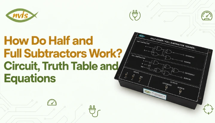
This does not make half and full subtractor circuits covered in this article irrelevant. They remain standard way subtraction is taught in digital electronics courses because they build Boolean design skills directly, from truth table to equation to gate level circuit, and they appear frequently as standalone circuits in lab experiments, viva questions and competitive exams, even when production hardware favors adder based approach. Lab trainers such as Nvis 6554 Adders and Subtractors trainers are built specifically around this dedicated circuit approach, letting students patch together half and full subtractor stages by hand and observe truth table behavior directly on hardware rather than only in simulation.
Half and Full Subtractors in Exams: GATE, SSC JE and RRB JE
Half and full subtractors fall under combinational logic circuits, a core topic in the Digital Logic section of GATE syllabus for Computer Science, Electronics and Communication, and Electrical Engineering papers. Questions typically test truth table derivation, Boolean simplification of borrow output using Karnaugh maps, and gate count comparisons between different implementations of the same circuit, exactly the kind of derivation worked through in this article.
For SSC JE and RRB JE, digital electronics topics may be tested through objective questions covering concepts such as logic gates, Boolean algebra, and combinational circuits. Questions on these topics can involve truth tables, Boolean expressions, logic-gate implementations, and circuit diagrams. Practicing the derivation of these results can help candidates handle questions that require more than recalling the final equations.
Digital logic fundamentals may also be relevant in technical selection processes for engineering roles at organisations such as BEL, BHEL, ISRO and Power Grid, depending on the role and recruitment process.
Conclusion
Half and full subtractors are combinational circuits built entirely from XOR, AND, OR and NOT gates, and the difference between them comes down to one input: borrow in. A half subtractor handles a single bit with no incoming borrow, producing D = A ⊕ B and Bo = A’B. A full subtractor adds Bin input so multi bit subtraction can be chained bit by bit, producing D = A ⊕ B ⊕ Bin and Bout = A’B + A’Bin + BBin, and it can be built directly from two half subtractors plus one OR gate.
Working through truth table derivation by hand, confirming Boolean equations against it, and tracing a multi bit example like one worked through above builds a kind of understanding that holds up in a lab viva or a GATE style question, not just on a memorized diagram. For hands-on practice with actual gate level behavior of these circuits, a digital electronics trainer such as Nvis 6554 lets students patch together half and full subtractor stages and verify each truth table row directly on hardware.
FAQs
What is the main difference between a half subtractor and a full subtractor?
A half subtractor has two inputs (A and B) and does not accept a borrow in, so it can only be used for the least significant bit of a subtraction. A full subtractor has three inputs (A, B and Bin), which lets it be chained with other full subtractors to perform multi bit binary subtraction.
What is Boolean equation for a full subtractor's difference and borrow output?
Difference output is D = A ⊕ B ⊕ Bin. The output, after Karnaugh map simplification, is Bout = A’B + A’Bin + BBin.
Can a full subtractor be built using two half subtractors?
Yes. First half subtractor processes A and B, second half subtractor processes first one’s difference output along with Bin, and an OR gate combines two intermediate borrow outputs to produce final Bout.
How many gates are needed to build a half subtractor and a full subtractor?
A half subtractor needs three gates: one XOR, one AND and one NOT. A full subtractor can be implemented using seven basic gates from the simplified Boolean equations, or seven gates using two half subtractors and an OR gate.
Why do real processors use adders instead of subtractors for binary subtraction?
Yes. They fall under combinational logic circuits in Digital Logic syllabus for GATE (CS, ECE and EE papers) and are a standard topic in SSC JE and RRB JE Electronics and Electrical papers, often tested through truth table and circuit diagram questions rather than pure recall.
Are half and full subtractors important for GATE, SSC JE and RRB JE exams?
Yes. They fall under combinational logic circuits in Digital Logic syllabus for GATE (CS, ECE and EE papers) and are a standard topic in SSC JE and RRB JE Electronics and Electrical papers, often tested through truth table and circuit diagram questions rather than pure recall.


