





TL;DR
- The article is aimed at engineering students, diploma students, and GATE/SSC JE/RRB JE aspirants to have an easy-to-understand explanation about multiplexer and demuxer concepts from their exams.
- A multiplexer (MUX) selects one of several input signals and routes the selected signal to a single output. A demultiplexer (DEMUX) performs the reverse operation by routing one input signal to one of several outputs based on the select lines.
- The number of data inputs in a MUX or outputs in a DEMUX is determined by 2^n, where n is the number of select lines.
- Truth table and Boolean expression of a 2:1, 4:1, and 8:1 multiplexer is given here with some example calculations to show which select line outputs an output.
- The multiplexer is a part of GATE ECE combinational circuit course; it also appears as an exam question for MUX and DEMUX questions during SSC JE, RRB JE, and PSU technical interview exams.
Also Read,
- Arduino for Embedded Systems Learning: Setting Up Your First Lab Project
- IoT Microcontroller Projects for Engineering Students: From Sensor to Cloud
- ARM Cortex M Microcontrollers Explained: Architecture for Embedded Engineering Students
What You Need to Know Before Multiplexers and Demultiplexers
A multiplexer is a combinational circuit whose output depends on the current input and select-line values, not on previous states. A demultiplexer is also a combinational circuit, but it routes one input signal to one of several outputs based on the select lines. This is different from sequential circuits such as flip-flops and counters, whose outputs can depend on previous states. There are three basic concepts related to digital circuits that should be understood first. Firstly, binary select lines are available for choosing between two options – 0 and 1. With n select lines, a circuit can distinguish between 2^n unique combinations, and this single relationship governs size of every multiplexer and demultiplexer discussed below. Also secondly, basic logic gates such as AND, OR, and NOT gates are used to construct MUX and DEMUX circuits from within a computer system. Thirdly, an idea about how to distinguish between a data line and a control line; within those systems there are data lines that transmit real-time information whereas selection lines determine whether any particular data line should be activated or not. Two common points of confusion when learning multiplexer truth tables are understanding the select-line combinations and identifying which input is connected to the output.What Is a Multiplexer?
Multiplexers are also known by their acronyms such as “MUX” which refers to an electronic device that combines several input signals into one signal through selection paths based on control lines. Any particular selection of lines will determine which single input is linked to an output while others are not considered at once. A multiplexer has an input count that must be a power of 2 based on how many selection wires there are to it. With n select lines a multiplexer is able to pick out from 2^n signals. This gives a standard family of multiplexer sizes: 2:1 (1 select line, 2 inputs), 4:1 (2 select lines, 4 inputs), 8:1 (3 select lines, 8 inputs), and 16:1 (4 select lines, 16 inputs). Multiplexers are similar to rotary selectors for choosing between multiple channels on an antenna set. Lines are switches; only a selected station’s signal is heard by an individual at that time whereas other stations’ signals stay unheard. The same applies to switching behavior; however, an electronic switch is made up of logic gate circuits instead of physical contacts.2:1 Multiplexer: Simplest Case
A 2:1 multiplexer has two data inputs (I0 and I1), one select line (S), and one output (Y). When S = 0, input I0 passes to output; when S = 1, input I1 passes to output.|
S |
Y |
| 0 | I0 |
| 1 |
I1 |
4:1 Multiplexer
A 4:1 multiplexer has four data inputs (I0 to I3), two select lines (S1 and S0), and one output (Y). two select lines together produce four unique combinations, each of which activates exactly one input line.|
S1 |
S0 | Y |
|
0 |
0 |
I0 |
|
0 |
1 |
I1 |
|
1 |
0 |
I2 |
| 1 | 1 |
I3 |
8:1 and 16:1 Multiplexers
An 8:1 multiplexer follows the same pattern with three select lines (S2, S1, S0) selecting among eight inputs (I0 to I7), and its Boolean expression has eight product terms, one for each 3 bit select combination. The 16:1 multiplexer has four select lines and sixteen inputs. Instead of constructing them anew each time, a bigger multiplexer can be built through a combination of several small ones. An 8:1 multiplexer can be constructed using two 4:1 multiplexers followed by one 2:1 multiplexer. The two 4:1 multiplexers share two select lines, while the third select line controls the final 2:1 multiplexer.. Two select lines are applied to both 4:1 multiplexers, while the remaining select line controls the final 2:1 multiplexer. Two select lines are shared by the 4:1 multiplexers, while the third select line controls the 2:1 multiplexer that chooses between their outputs. The same modular design applies to commercial multiplexer ICs as well; this method of implementation is used by engineers when they need an efficient way of performing any kind of logic operation through multiplexers which appear frequently on test papers from universities like GATE level exam questions.What Is a Demultiplexer?
A demultiplexer (DEMUX) performs the reverse data-routing operation of a multiplexer. It has one data input, multiple outputs, and select lines that determine which output receives the input signal. The select-line combination determines which output is selected. In the active-high convention used in this example, the selected output follows the input while the other outputs remain at logic 0. Just like multiplexers, the number of outputs is determined by an 2^n rule according to the number of select lines: a 1:2 demultiplexer requires 1 select line, a 1:4 demultiplexer needs 2, a 1:8 demultiplexer needs 3, and a 1:16 demultiplexer needs 4. A DEMUX can be compared to a railway junction where one incoming route can be directed to one of several outgoing tracks. The select lines act like switching controls that determine the destination based on the selected route. A train is unchanged by switching to another track but it can be redirected towards a different location depending upon that switch setting. Electrically, the input signal remains the same; the select lines simply determine which output receives that signal.1:4 Demultiplexer Truth Table
A 1:4 demultiplexer has one data input (D), two select lines (S1, S0), and four outputs (Y0 to Y3).|
S1 |
S0 | Y0 | Y1 | Y2 |
Y3 |
|
0 |
0 | D | 0 | 0 |
0 |
| 0 | 1 | 0 | D | 0 |
0 |
|
1 |
0 | 0 | 0 | D |
0 |
|
1 |
1 | 0 | 0 | 0 |
D |
Multiplexer and Demultiplexer: How They Work Together
Multiplexers are often paired with demultiplexers for sharing of a single transmission line between many sources and receivers. On the transmission side, there is a multiplexer which picks out from among the multiplexer, selects one of the inputs and sends it through the shared channel.. At the receiving end, the demultiplexer routes the incoming signal to the appropriate output line based on the select lines. To ensure proper operation, the multiplexer and demultiplexer must use corresponding select-line combinations; therefore, For a simple MUX-DEMUX arrangement, the receiver uses the corresponding select-line combination to route the transmitted signal to the intended output. In a simple MUX-DEMUX arrangement, the transmitter and receiver need coordinated selection or timing information so that the receiver can correctly identify the intended channel. This principle is related to time-division multiplexing (TDM), which allows multiple signals to share a communication channel.Worked Example: Implementing a Boolean Function Using a Multiplexer
A frequently asked question in university exams and competitive papers is to implement a given Boolean function using a multiplexer rather than discrete logic gates. Consider function: F(A, B, C) = Σm(1, 3, 5, 6) This means F = 1 for minterms 1, 3, 5, and 6, and F = 0 for all other combinations of A, B, C. Step 1: Choose multiplexer size. With three variables, an 8:1 multiplexer can implement this function directly, using A, B, and C as three select lines and tying each data input to either 0 or 1 based on the truth table. Step 2: Build the truth table.|
A |
B | C | Minterm | F |
| 0 | 0 | 0 | m0 |
0 |
| 0 | 0 | 1 | m1 |
1 |
|
0 |
1 | 0 | m2 | 0 |
| 0 | 1 | 1 | m3 |
1 |
| 1 | 0 | 0 | m4 |
0 |
|
1 |
0 | 1 | m5 | 1 |
| 1 | 1 | 0 | m6 |
1 |
| 1 | 1 | 1 | m7 |
0 |
Common Multiplexer and Demultiplexer ICs
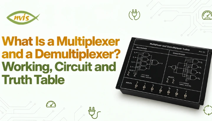
In practice, multiplexers and demultiplexers are implemented using multiple logic gates or dedicated ICs. TTL and CMOS logic families include ICs that implement multiplexer, demultiplexer, and related logic functions. 74151 is an 8:1 multiplexer that comes as a single IC package, often found at digital design labs and cited by textbooks due to its simple pin configuration. The 74153 package has two separate 4:1 multiplexers on a single chip for use where there is need of two independent data selection operations at same time. The 74LS138 is primarily a 3-to-8-line decoder with active-low outputs, but it can also be used as a demultiplexer by using one of its enable inputs as the data input while the three address inputs act as select inputs. Because its outputs are active-low, its demultiplexer behavior is inverted compared with the active-high DEMUX example above, which is worth noting because exam questions sometimes test decoder to demultiplexer conversion specifically. The manufacturer datasheet is a reliable source for precise pin configuration details as well as electrical specifications because there may be slight differences among manufacturers’ models and packages. For students who want to verify this behavior physically rather than only on paper, a dedicated multiplexer and demultiplexer trainer kit lets you build and test a 4 to 1 line multiplexer and a 1 to 4 line demultiplexer using onboard SPDT switches for select line control and LED indicators to read output directly, which makes truth table behavior visible rather than something to only memorize.Applications of Multiplexers and Demultiplexers
Multiplexers and demultiplexers are used in communication, computer, and control systems to route or share signals efficiently when multiple data sources need to use limited communication paths. In communication systems, multiplexing techniques such as time-division multiplexing (TDM) allow multiple signals to share a communication channel. A multiplexer is one of the circuit-level building blocks that can be used for signal selection and routing. A multiplexer is an electronic device that can be found inside of computers for selecting among several inputs going towards one output line within its circuitry. A 2^n:1 multiplexer can implement any Boolean function of n variables by using those variables as the select lines and connecting each data input to the corresponding 0 or 1 value from the function’s truth table hence this problem is often asked on exams. In a communication system, a demultiplexing stage can separate a multiplexed stream into its constituent channels or signals. In memory and I/O systems, decoders are commonly used to select specific memory locations or peripheral devices based on address inputs.Multiplexer vs Demultiplexer: Quick Comparison
| Parameter | Multiplexer (MUX) | Demultiplexer (DEMUX) |
| Number of inputs | Multiple (2^n) | Single |
| Number of outputs | Single | Multiple (2^n) |
| Function | Selects one input, routes to output | Routes single input to one selected output |
| Also known as | Data selector | Data distributor |
| Select lines | n lines for 2^n inputs | n lines for 2^n outputs |
| Common IC examples | 74151, 74153 | 74138 (as decoder/demux) |
| Typical use | Combining multiple signals onto one line | Distributing one signal to multiple destinations |
Where This Topic Shows Up in Indian Technical Exams
In the GATE 2026 Electronics and Communication Engineering syllabus, multiplexers are covered under Digital Electronics and combinational logic topics. This makes multiplexers a relevant concept for GATE ECE preparation. Multiplexers remain part of the current GATE 2026 EC Digital Electronics syllabus, since these are core combinational logic topics evaluated separately from microprocessor architecture. Beyond GATE, digital electronics fundamentals including multiplexers and demultiplexers are commonly tested in SSC JE and RRB JE electronics and electrical papers, and the same concepts frequently come up in technical interviews for PSU recruitment in electronics, telecommunication, and instrumentation roles. Candidates preparing for these exams should be comfortable deriving truth tables from scratch, writing Boolean expression for a given multiplexer or demultiplexer size, and solving Boolean function implementation problems of kind worked through earlier in this article, since these tend to appear as both objective and descriptive questions.Multiplexer and Demultiplexer: What to Remember
Multiplexers choose among many inputs for sending them through an output channel whereas demultiplexers take one input signal and route it to one of several output channels based on the select lines; both are controlled via select lines following the 2^n relationship between select line count and data line count. Knowledge of truth tables and Boolean expressions for 2:1 and 4:1 can be used to generalize this concept to 8:1, 16:1, and more complex multiplexers and demultiplexers. They are useful for selecting and distributing signals in digital systems, including communication and computer systems. Their truth tables, Boolean expressions, and logic-function implementation are important concepts for digital-electronics exam preparation. Once you understand these concepts, practice Boolean-function problems before moving on to related topics such as decoders, encoders, and flip-flops. The worked example above provides a good starting point.FAQs
What is the main difference between a multiplexer and a demultiplexer?
A multiplexer has multiple inputs and one output, selecting one input to pass through based on select lines. A demultiplexer has one input and multiple outputs, routing that single input to one selected output. They perform opposite operations.
How many select lines are needed for an 8:1 multiplexer?
An 8:1 multiplexer needs three select lines, since 2^3 = 8. In general, a multiplexer or demultiplexer with n select lines can handle 2^n data lines.
Can a multiplexer be used to implement any Boolean function?
Yes. A 2^n:1 multiplexer can implement any Boolean function of n variables by connecting the function’s variables to select lines and function’s truth table output values to data inputs, as shown in the worked example in this article.
Is 74138 IC a multiplexer or a demultiplexer?
The 74138 is a 3-to-8-line decoder/demultiplexer. With suitable enable connections, one enable input can be used as the data input while the three address inputs act as select inputs. Its outputs are active-low, so its behavior differs from an active-high 1:8 DEMUX truth table.
Are multiplexers part of GATE syllabus?
Yes. Multiplexers are explicitly listed in the Digital Electronics section of the GATE 2026 Electronics and Communication Engineering syllabus, along with Boolean algebra, Karnaugh maps, and decoders. Demultiplexers are not named separately in syllabus but follow directly from the same combinational logic concepts.
What is the practical difference between a multiplexer and a simple switch?
A mechanical switch requires physical movement to change connections, while a multiplexer changes its output instantly based on electrical logic level applied to its select lines, making it suitable for high speed digital switching where mechanical switches would be far too slow.


