





TL;DR
- This blog is for engineering department heads, lab instructors, and electronics, electrical, and instrumentation students setting up or evaluating a digital electronics laboratory, not just browsing a generic equipment list.
- A digital electronics laboratory needs five categories working together: core lab hardware, test and measurement instruments, ICs and components, simulation and design software, and physical layout and maintenance practices.
- Most equipment lists online stop at listing ICs and trainer kits; a lab actually needs test instruments like a CRO or DSO, a function generator, and a logic probe to diagnose electrical behavior a trainer kit alone cannot show.
- Which experiments a lab must support, based on the relevant university or institutional syllabus and applicable curriculum guidelines, should guide the choice of IC families, trainer kits, and socket count.
- A well equipped digital electronics lab should let a student move from a Boolean expression to a verified physical circuit and back again, using both simulation and hardware, because this dual workflow reflects the practical skills developed in many university laboratory courses and can also help students discuss circuit behavior in technical interviews.
Also Read,
- Arduino for Embedded Systems Learning: Setting Up Your First Lab Project
- IoT Microcontroller Projects for Engineering Students: From Sensor to Cloud
- ARM Cortex M Microcontrollers Explained: Architecture for Embedded Engineering Students
What Is the Purpose of a Digital Electronics Laboratory?
Before listing equipment, it helps to be clear on what a digital electronics lab is actually trying to teach, since that purpose is what every equipment decision should trace back to. A digital electronics lab exists to close the gap between theoretical circuit design and physical circuit behavior. A student can derive a truth table, simplify a Boolean expression using a Karnaugh map, and draw a state diagram entirely on paper or in a simulator, but none of that confirms design actually works once real voltage levels, real propagation delays, and real wiring are involved. A logic gate IC that looks correct on a datasheet can still behave unexpectedly if its supply voltage sags, if an input is left floating instead of tied to a defined logic level, or if two outputs are accidentally shorted together. A lab is where a student learns to recognize and diagnose exactly these failure modes, which a simulation, however accurate its logical model, does not reproduce. This purpose splits naturally into two kinds of work, and a lab’s equipment list has to support both. First is circuit construction: wiring an IC based combinational or sequential circuit correctly, which mainly requires a trainer kit or breadboard, a power supply, and ICs themselves. Second is circuit verification: confirming that the constructed circuit actually behaves as designed, which requires test instruments capable of showing logic levels, timing relationships, and signal quality, not just a static LED indicator. A lab equipped only for construction, with no way to verify signal timing beyond a slow blinking LED, teaches students to trust a working demo without teaching them to diagnose a broken one.What Core Hardware Does a Digital Electronics Lab Need?
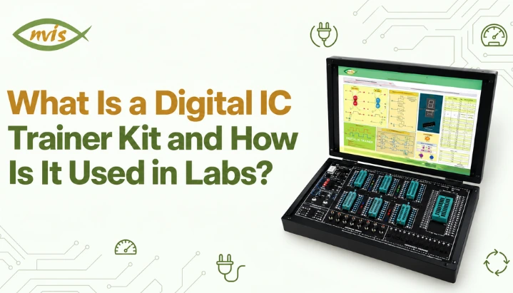
core hardware is what a student directly wires and interacts with during an experiment, and it sets a practical ceiling on which circuits a lab can support at all. A regulated DC power supply is a non-negotiable starting point, since digital ICs require an appropriate and sufficiently stable supply voltage to operate within their specified conditions. Traditional 74-series TTL ICs commonly use a nominal 5 V supply, while many 4000-series CMOS devices support a wider supply-voltage range. The exact operating range depends on the specific IC family and part number. A lab needs either individual bench power supplies at each workstation or a trainer kit with a built in regulated supply, since an unregulated or fluctuating voltage is one of most common causes of an IC behaving unpredictably during an experiment, and diagnosing that cause without a stable reference supply wastes significant lab time. Digital IC trainer kits are a central piece of equipment in many digital electronics labs. Depending on the model, they may combine a regulated power supply, ZIF IC sockets, logic input switches, LED indicators, and an onboard clock generator on a single board. ZIF socket lets an IC be inserted or removed without any force on its pins, which matters considerably for equipment shared across dozens of student groups every semester, since repeated insertion and removal can put mechanical stress on DIP IC pins, making a ZIF socket useful in a shared laboratory environment. NvisTech’s guide to digital IC trainer kits covers exactly how these subsystems work together during an experiment, from ZIF socket handling to reading a wrong LED output as a diagnostic clue rather than just a failure. Breadboards and discrete IC bases still have a role even where trainer kits are available, particularly for larger multi IC projects, such as a digital clock built from cascaded counter ICs, where a trainer kit’s fixed socket count and switch and LED count can become a practical constraint. A lab that only ever uses trainer kits for every experiment, without giving students breadboard experience, leaves a gap for kind of open ended project work that a fixed trainer kit layout cannot accommodate. Patch cords and connecting wires, in sufficient quantity and in more than one color, round out the core hardware list. This sounds like a minor detail, but a lab that runs short of patch cords, or where cords are inconsistently colored so students cannot visually trace a connection at a glance, loses meaningful time every session to wiring confusion that has nothing to do with actual circuit being studied.What Test and Measurement Instruments Are Required?
This is the category most equipment lists shortchange, and it is exactly where a lab’s ability to teach diagnostic skill, rather than just circuit assembly, actually lives. A CRO or, more commonly in newer labs, a digital storage oscilloscope (DSO) is highly useful for observing actual signal waveforms and becomes particularly important for sequential-logic and timing-related experiments rather than on off LED indication a trainer kit alone provides. An LED tells a student whether an output is currently high or low; An oscilloscope shows waveform rise time, fall time, glitches, and timing relationships between signals. These observations can help students understand propagation delay, setup and hold-time behavior, and other timing effects. Where JK flip-flop experiments are included, an oscilloscope can help students examine the timing behaviour associated with race-around conditions in level-triggered JK configurations. A dual-channel oscilloscope is particularly useful for sequential-circuit experiments because it allows students to compare signals such as a clock and flip-flop output simultaneously, since comparing two waveforms against each other is a routine diagnostic step. A function or pulse generator supplies a controllable clock or trigger signal independent of a trainer kit’s fixed onboard clock, which matters for experiments that need to vary clock frequency deliberately, such as demonstrating a ripple counter’s accumulated propagation delay at increasing frequencies until the counter’s output becomes unreliable. Without an external, adjustable clock source, this kind of frequency dependent behavior is difficult to demonstrate directly. A digital multimeter (DMM) is needed for measuring supply voltage, checking continuity on a suspected broken connection, and confirming a specific pin’s DC voltage level when an LED reading alone is ambiguous. It is a lower cost, higher volume instrument compared to an oscilloscope, and a lab should generally stock more DMMs than oscilloscopes so each student group has ready access to one without waiting. A logic probe can indicate whether a signal is at a recognised logic-high or logic-low state, and some models can also indicate high-impedance or pulse activity, is a fast way to trace a signal through a circuit without setting up an oscilloscope for every check, and is particularly useful for a student learning to debug a wiring error methodically rather than by trial and error. A logic analyzer, which captures and displays multiple digital signals simultaneously over time, is a more advanced instrument that becomes genuinely useful once a lab’s syllabus extends into multi bit bus behavior or FPGA based digital design, though it is not essential for a lab focused primarily on discrete IC combinational and sequential circuits. An IC tester, where available, can check supported ICs against expected logic behavior and help identify faulty devices before they are used in an experiment, saving considerable diagnostic time in a shared lab environment, where a genuinely faulty IC is a real and recurring possibility after repeated use across many student groups. Without an IC tester, a faulty IC is often only discovered after a student has already spent time incorrectly assuming their own wiring is at fault.What Components and Consumables Should a Lab Stock?
Beyond trainer kits and instruments, a digital electronics lab needs an actual inventory of ICs and small parts, and the specific IC families stocked should be driven directly by the experiments the syllabus requires. For combinational logic, a lab may stock commonly encountered 74-series devices such as 7400 NAND, 7402 NOR, 7404 NOT, 7408 AND, 7432 OR, and 7486 XOR, along with suitable equivalents from newer 74-series families where applicable, along with devices such as the 7483 4-bit binary adder, 7485 magnitude comparator, multiplexers, decoders, and display-driver ICs, depending on the syllabus, multiplexer and decoder ICs such as the 74151 and 74138, and a BCD to seven segment decoder such as 7447. For sequential logic, inventory needs flip flop ICs (7474 dual D, 7476 dual JK), decade and binary counters (7490, 74193), and shift register ICs (74164, 74195). A lab supporting CMOS based experiments alongside or instead of TTL needs corresponding 40 series parts, such as 4013 dual D flip flop, which are associated with CMOS logic and generally have different supply-voltage and current characteristics from traditional 74-series TTL devices. Display and indicator components, including seven-segment displays, including common-anode and common-cathode variants, selected to match the output requirements of the decoder or driver IC being used, LED bar graphs, and small discrete LEDs, are needed both as standalone experiment outputs and as replacements for a trainer kit’s built in indicators when those are already occupied. DIP switches and momentary push buttons supplement a trainer kit’s built in logic switches, particularly for larger projects that need more independent inputs than a single trainer kit provides. A stock of breadboard compatible resistors (particularly current limiting values for LEDs and pull up or pull down values for switch inputs), along with a reasonable supply of connecting wire in multiple gauges, rounds out the consumables list. None of this is expensive individually, but a lab that runs out of a specific IC or a specific resistor value mid semester, with no fast reordering process, effectively loses that experiment for remaining student batches until stock is replenished.What Software Tools Support a Digital Electronics Lab?
A modern digital electronics lab is not purely a hardware exercise, and simulation software plays a specific, complementary role rather than replacing hardware work covered above. General purpose circuit simulation tools, along with logic design focused simulators, let a student design and verify a circuit’s logical correctness before committing it to physical hardware, catching a wrong truth table or Boolean simplification error before the circuit is built, reducing the risk of wiring mistakes or unnecessary component damage during hardware testing. This pre lab verification step is genuinely valuable time wise, since a design that fails in simulation would otherwise consume physical lab time discovering the same logic error through trial and error on hardware. Where a lab’s syllabus extends into programmable logic, an HDL (hardware description language) toolchain such as Xilinx Vivado, used with VHDL or Verilog and an FPGA development board, becomes relevant. Modern digital design workflows often use programmable logic devices such as FPGA often use programmable logic devices such as FPGAs alongside or instead of discrete logic ICs, particularly in prototyping and more advanced digital-design applications. Where a program includes programmable logic or FPGA-based design, adding HDL and FPGA work can give students exposure to digital-design workflows used in many hardware development and prototyping environments. An important distinction, covered in more depth in NvisTech’s comparison of a digital IC trainer kit against a trainer kit simulator, is that simulation software verifies logical correctness under idealized conditions, while physical hardware verifies actual electrical correctness, including voltage levels, timing, and wiring faults that only show up once real components are involved. A lab’s software budget should support pre lab design and post design HDL work, not attempt to substitute for physical trainer kits and test instruments covered earlier.How Should a Digital Electronics Lab Be Organized and Maintained?
Equipment alone does not make a functioning lab; how it is laid out, stored, and maintained determines whether that equipment stays usable and safe across an academic year of continuous student use. Workstation layout should give each student group enough bench space to keep a trainer kit, an oscilloscope or shared access to one, a multimeter, and a component tray open simultaneously, without cables from adjacent stations tangling together. A lab where students must clear their bench to make room for an instrument they need mid experiment loses time to reorganization that has nothing to do with the circuit itself. Grouping ICs, resistors, and small components in labeled trays or bins, organized by IC number or component value rather than by arrival date, is a small organizational choice that measurably speeds up experiment setup, particularly for a lab running multiple sections through same equipment across a week. Electrical safety practices matter even though digital logic ICs operate at low voltages, since mains supply feeding bench power supplies and instruments does not. Standard precautions, proper earthing of instrument chassis, residual current protection on lab’s mains circuit, and a clear rule to avoid changing circuit wiring while power is applied, unless the equipment and procedure are specifically designed for live connections, are standard laboratory practices that should be enforced regardless of how low voltage actual experiment circuits are. Maintenance is the piece most frequently neglected once a lab is operational. ICs do fail with use, and a periodic IC testing or screening routine can help identify faulty parts before they create unnecessary troubleshooting during student experiments scattered through trainer kit sockets and component trays, each one a future source of a student wrongly assuming their own wiring is at fault. Instruments need periodic calibration checks, particularly oscilloscopes and function generators, since a drifted calibration can produce a reading that looks plausible but is quietly wrong. A lab that budgets for equipment purchase but not for ongoing maintenance can see its effective, usable equipment count decline over time, particularly under heavy student use.What Experiments Should a Digital Electronics Lab Cover?
The equipment above is not chosen in isolation; it should support the experiments specified by the relevant university or institutional syllabus. Many such syllabi cover a similar core of combinational and sequential logic experiments. Common undergraduate digital electronics lab experiments include verification of Boolean laws and De Morgan’s theorems, half and full adders and subtractors, multiplexers, demultiplexers, counters, and shift registers. Depending on the syllabus, students may also construct a 4-bit parallel adder using a suitable IC such as the 7483, verify magnitude comparison using a comparator IC such as the 7485, implement functions using multiplexers and decoders, and perform BCD-to-seven-segment decoding, magnitude comparison using 7485, multiplexer and demultiplexer based function implementation using 74151 and 74138, and BCD to seven segment decoding. At the sequential-logic level, a standard experiment set may include clocked SR and JK flip-flop verification, shift register configuration in all four modes (serial in serial out, serial in parallel out, parallel in serial out, and parallel in parallel out), ring and Johnson counter construction, and Mod N counter design, typically asking students to design a counter for a specific modulus and verify it on hardware. NvisTech’s guide to digital electronics projects for engineering students works through several of these designs, including a full Mod 6 synchronous counter example, in more depth than a typical lab manual covers, and underlying flip flop behavior each of these experiments depends on is covered in NvisTech’s guide to flip flop types and working. Mapping this experiment list back onto equipment sections above clarifies why each category matters. Combinational experiments can generally be performed with an IC inventory, trainer kit or breadboard, and basic measurement tools, while sequential experiments create a stronger need for an oscilloscope and adjustable clock source because they involve clock-dependent state changes and timing relationships. Sequential experiments are where an oscilloscope, function generator, and logic probe become especially useful, since they allow students to observe clock edges, signal timing, and transitions that may not be visible from a final LED output alone. A lab that invests in test instruments can still run a combinational experiment set adequately, but sequential experiments are where gaps in test equipment can become more noticeable, particularly when students need to examine clock transitions and timing relationships rather than just slower lab sessions.Digital Electronics Labs in Indian Engineering Colleges
Many Indian engineering colleges and polytechnics include digital electronics laboratory work as part of electronics and related engineering programs. It is commonly included as part of undergraduate electronics-related laboratory coursework, although the semester and course title vary by university, although the semester and course title vary by university, using laboratory manuals and curricula that may be aligned with institutional or university requirements and, where applicable, broader AICTE curriculum guidance. ITI electronics trade courses and diploma polytechnic programs run a similar, though typically more compact, version of the same lab, with practical examinations that require a student to wire an assigned circuit on physical hardware within a fixed time and explain its behavior to an examiner. This practical examination format is precisely why equipment categories covered above matter as a complete set rather than piecemeal. A student who has only practiced on a simulator, without experience wiring and verifying circuits on physical hardware, may find practical exams more challenging when they require hands-on circuit construction and troubleshooting.Does Lab Equipment Choice Matter for GATE, SSC JE, and RRB JE Preparation?
A digital electronics lab’s equipment list is not itself an examinable topic in any competitive exam, but concepts it is built to demonstrate are covered in the relevant digital-logic portions of several engineering competitive-exam syllabi, which makes connection indirect but genuinely significant. Digital logic and related topics form part of the GATE Electronics and Communication Engineering (ECE) and Electrical Engineering (EE) syllabi, covering number systems, Boolean algebra and minimization, combinational circuit design, and sequential circuit design including flip flops, counters, and registers. GATE Computer Science and Information Technology also covers digital logic as prerequisite knowledge for computer organization topics. Physically building and debugging combinational and sequential circuits can reinforce the concepts tested in GATE questions on counters, flip-flops, and related digital logic topics, although exam preparation still requires focused theoretical and numerical practice. For SSC JE and RRB JE, the relevance of digital logic depends on the specific post and current examination syllabus. Candidates should check the latest official notification and syllabus for the relevant recruitment focusing instead on broader electrical and basic electronics fundamentals. Practical electronics experience may also be relevant in some technical interviews or assessments for engineering roles, depending on the organization, recruitment process, and role for electronics and instrumentation roles, where candidates may be asked to explain circuit operation, troubleshooting approaches, or projects involving practical electronics. Aspirants should verify current year’s official syllabus notification from SSC and RRB directly before assuming any subject’s exact weightage, since exam patterns are revised periodically.Basic Lab Setup vs a Well Equipped Lab
equipment categories above scale differently depending on a department’s budget and depth of syllabus it supports, and it helps to see differences laid out directly.| Equipment Category | Basic Setup | Well Equipped Lab |
| Core hardware | Breadboards, individual bench power supplies | Digital IC trainer kits with built in supply, ZIF sockets, and clock generator |
| Test instruments | Digital multimeters only | DMMs, dual trace CRO or DSO, function generator, logic probe |
| Diagnostic tools | None (visual inspection only) | IC tester, logic analyzer for bus level and FPGA work |
| Component inventory | Core 74 series gates and one or two flip flop ICs | Full 74 series and 40 series range, counters, shift registers, display decoders |
| Software | None or informal use of free simulators | Licensed circuit simulator plus an HDL toolchain for FPGA based experiments |
| Experiment coverage | Combinational logic only | Full combinational and sequential syllabus, extendable into FPGA based design |
Building or Upgrading a Digital Electronics Lab
A department setting up a new lab or upgrading an existing one should start from experiment list its syllabus actually requires, then work backward to specific trainer kit socket count, IC families, and instrument tier that the experiment list demands, rather than starting from a generic equipment list and hoping it covers the syllabus. A trainer kit such as NV6550 Digital IC Trainer, built around ZIF sockets, logic switches, LED indicators, and an onboard clock generator, is designed to cover standard combinational and sequential experiment set on a single board, which simplifies core hardware decision considerably, but it still needs to sit alongside test instruments, component inventory, and software covered above to function as a complete lab rather than just a collection of trainer kits. categories covered in this article, core hardware, test instruments, component inventory, software, and physical organization, are not independent purchase decisions. A lab’s overall capability depends on how well its hardware, instruments, components, software, and maintenance practices work together and a department that spends its full budget on trainer kits while treating oscilloscopes and logic probes as optional ends up with students who can build a circuit but cannot fully explain why it works or why it occasionally does not.FAQs
What is the single most important piece of equipment in a digital electronics lab?
There is no single most important piece since a lab needs both construction equipment (a trainer kit or breadboard with a regulated power supply) and verification equipment (at minimum a multimeter and ideally an oscilloscope) to teach circuit building and circuit diagnosis together. A lab strong in one category but missing another leaves a genuine gap in what students can learn.
Do digital electronics labs still need physical trainer kits given how common circuit simulators have become?
Yes. Simulators verify idealized logical behavior quickly and at no component risk, but only physical hardware shows real voltage levels, timing behavior, and wiring faults,which is particularly relevant to university lab practicals and can also help students discuss practical circuit behavior in technical interviews. Many engineering programs combine simulation or design work with hands-on hardware experiments, although the exact balance depends on the institution and syllabus.
What test instruments does a digital electronics lab need beyond a multimeter?
A dual trace oscilloscope or digital storage oscilloscope, a function or pulse generator for an adjustable clock source, and a logic probe for fast point to point signal tracing are core additions. An IC tester and, for FPGA capable labs, a logic analyzer round out a well equipped setup.
How many ICs and trainer kits does a digital electronics lab need?
This depends on batch size and number of parallel experiment stations, but IC families should be chosen to match syllabus experiment list directly, covering standard 74 series gates, an adder and comparator IC, multiplexer and decoder ICs, flip flop ICs, and counter and shift register ICs, rather than stocking parts speculatively.
Is FPGA based equipment necessary for a basic digital electronics lab?
Not for a lab focused strictly on standard undergraduate combinational and sequential logic syllabus, which is built around discrete 74 series and 40 series ICs. FPGA trainer boards and an HDL toolchain become relevant once a program’s curriculum extends into programmable logic design, which increasingly reflects how digital design work is actually done in industry and at PSUs.
Does equipment in a digital electronics lab affect GATE or PSU interview preparation?
Indirectly but meaningfully. equipment itself is not examined, but concepts it demonstrates, combinational and sequential circuit behavior, timing, and diagnosis of a faulty design, are core GATE ECE, EE, and CS topics and may be discussed in technical interviews, particularly when candidates are asked about circuits, projects, or practical electronics experience.

