





TL;DR
- This blog explains what a digital IC trainer kit is, its main components, how it works, and how students use it to test digital circuits in a laboratory. It also explains how the trainer kit fits into a digital electronics lab rather than treating it as just a product.
- Many digital IC trainer kits combine a regulated power supply, IC sockets, input switches, output LED indicators, and a clock or pulse source on one board, so a student can wire and test a digital IC based circuit without building support electronics from scratch each time.
- The trainer kit does not simulate logic, it runs real 74 series or CMOS ICs at their actual voltage levels, which is what separates it from a software simulator and why colleges still require hands-on trainer kit sessions alongside simulation based coursework.
- Understanding how a trainer kit is wired, from ZIF socket to LED indicator, makes it possible to verify a truth table, debug a wrong output, and design a new experiment on kit rather than just following a lab manual step by step.
- A digital IC trainer kit and a digital IC trainer kit simulator solve different problems, trainer kit teaches real electrical behavior, and simulator is a low cost way to plan and pre-verify a circuit before wiring it on actual hardware.
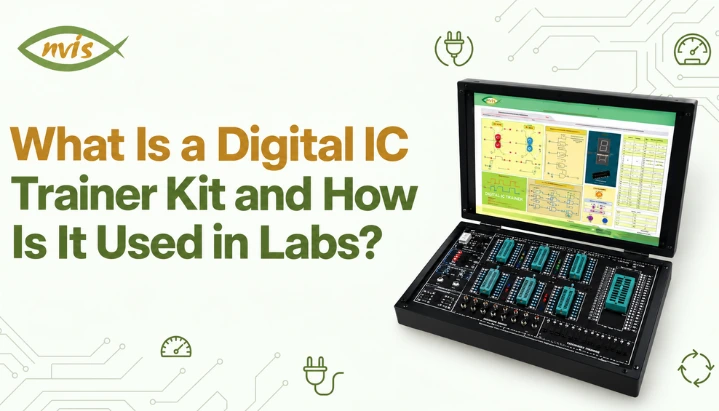
A digital IC trainer kit is a bench top lab instrument built to let students design, wire, and test digital logic circuits using real integrated circuits (ICs) without assembling a power supply, switches, and display indicators separately for every experiment. It combines a regulated DC power supply, zero insertion force (ZIF) IC sockets, toggle based logic switches, LED output indicators, and usually an onboard clock generator on a single portable board. The primary keyword here, digital IC trainer kit, covers a specific category of equipment distinct from a general purpose breadboard trainer or a purely software based digital IC trainer kit simulator.
Some manufacturers and course manuals refer to the same category of instrument more generally as a digital trainer kit or a trainer kit for digital electronics, and terms are used interchangeably in most Indian lab contexts as long as the board is built around digital logic ICs rather than analog components. The distinction that matters is not the name but the track it belongs to, since digital electronics labs in Indian engineering colleges and polytechnics run two parallel tracks today. One track uses software simulation tools to design and verify circuits quickly and without any risk of damaging a component. Another track still requires students to physically wire an IC based circuit and observe its behavior on real hardware, since A basic logic simulator generally does not model physical issues such as loose connections, damaged IC pins, or all real-world electrical effects. More advanced simulation tools can model some timing and electrical characteristics, depending on the model and simulator. A digital ic trainer kit is an instrument built for that second track.
This article covers what a digital IC trainer kit actually contains, how its components work together electrically, step by step process of running an experiment on one, a worked example verifying a full adder IC, where trainer kits fit against digital trainer kit simulator tools, and how trainer kits are used in Indian engineering labs and competitive exam preparation.
Also Read,
- Arduino for Embedded Systems Learning: Setting Up Your First Lab Project
- IoT Microcontroller Projects for Engineering Students: From Sensor to Cloud
- ARM Cortex M Microcontrollers Explained: Architecture for Embedded Engineering Students
What Is a Digital IC Trainer Kit? Fundamentals You Need First
Before internal wiring of a trainer kit makes sense, two prerequisite ideas need to be clear: what a digital IC is at hardware level, and what a lab trainer, as a category of instrument, is meant to solve.
A digital IC is a packaged semiconductor chip containing one or more logic circuits, typically logic gates, flip flops, counters, or registers, fabricated on a single piece of silicon and brought out through a fixed number of pins. The 74-series and 4000-series are two common logic IC families encountered in digital electronics labs. Older 74-series devices include TTL families, while many newer 74-series variants use CMOS technology. The 4000-series is primarily associated with CMOS logic. A digital IC only behaves correctly within its specified supply voltage range, and every experiment involving one requires that supply, along with a way to apply logic level inputs and observe logic level outputs.
A lab trainer, as a category of instrument, exists to remove every piece of supporting electronics an experiment needs other than the IC being studied itself. Without a trainer kit, wiring even a simple two input AND gate experiment on a plain breadboard means separately building a regulated 5V power supply, wiring toggle switches for each input with pull up or pull down resistors, and wiring an LED with a current limiting resistor for each output, all before actual IC under test is even connected. A digital IC trainer kit pre-built all of this supporting circuitry onto one board, so a student connects only IC and specific wires experiment requires.
What Are the Main Components of a Digital IC Trainer Kit?
A typical digital IC trainer kit includes several common subsystems, and understanding what each one does is what makes it possible to use kit for an experiment manual did not already describe.
A regulated DC power supply is the trainer kit’s most fundamental subsystem, since every digital IC needs a stable voltage to operate correctly. Classic 74-series TTL families generally operate from a nominal 5 V supply, with the exact allowable range depending on the specific family and device, and Many 4000-series CMOS ICs support a wider supply-voltage range than traditional 74-series TTL devices, although the allowable range depends on the specific IC and manufacturer. A trainer kit’s onboard power supply regulates incoming mains or external DC input down to this stable, IC safe voltage internally, so a student never needs to build or calibrate this circuit separately, and an unstable or out of range supply, one of most common causes of an IC behaving unpredictably or failing outright, is designed out of experiment entirely.
ZIF (zero insertion force) sockets are mounting points where the actual IC under test is inserted. A ZIF socket uses a small lever that opens and closes socket’s internal contacts mechanically, so an IC can be inserted or removed with no force applied to its pins at all. This matters because a standard IC socket or a breadboard hole requires IC’s pins to be pressed into a tight friction contact, and repeated insertion and removal this way bends or breaks pins over time, particularly on thin, closely spaced pins of a 14 pin or 16 pin DIP (dual in line package) IC. A ZIF socket greatly reduces mechanical stress on IC pins during repeated insertion and removal, which makes it useful for trainer kits that are shared across many students, since a lab kit shared across dozens of student groups every semester sees far more insertion cycles than a single IC would in a permanent circuit.
Logic input switches, typically toggle switches or slide switches, let a student apply a logic 0 or logic 1 to any pin of IC under test without wiring a separate voltage divider or pull up resistor for every input. Depending on the trainer design, each switch may be wired to provide a defined logic-high or logic-low level, often with circuitry that helps reduce unwanted switching effects.
LED output indicators provide a visual indication of the logic state at connected output lines, although whether an LED is on or off for logic 1 depends on the trainer kit’s indicator circuitry, giving an immediate visual readout of circuit’s output state without needing a multimeter or oscilloscope for basic verification. Each LED is wired through its own current limiting resistor internally, so connecting an IC’s output pin directly to indicator input is safe and does not require students to calculate or add a resistor manually.
An onboard clock generator, present on most trainer kits designed for sequential circuit work, produces a continuous square wave at a fixed or adjustable frequency, used to drive clock input of flip flops, counters, and registers during an experiment. Many trainer kits pair this with a manual clock pulser, a single debounced push button that generates exactly one clean clock pulse per press, which is essential for observing a sequential circuit’s state change one step at a time rather than watching a continuously running counter blur past on LED indicators.
How Does a Digital IC Trainer Kit Work?
At circuit level, a digital IC trainer kit works by presenting every subsystem described above as a fixed voltage, pre conditioned signal available at labeled connection points, so only wiring a student adds is between IC under test and those points.
When a student inserts an IC into a ZIF socket and wires a patch cord from a logic switch to one of IC’s input pins, switch delivers a clean logic level voltage directly to that pin, at exact voltage IC’s datasheet specifies as a valid logic 1 or logic 0 input, VIH and VIL respectively. IC then processes that input according to its internal logic function, and its output pin, wired through another patch cord to an LED indicator, drives that LED on or off depending on whether output voltage crosses IC’s defined output high threshold, VOH, or falls at or below its output low threshold, VOL.
This is core distinction between a trainer kit and a purely visual demonstration board: LED is not programmed to represent a logic state, it is physically driven by actual voltage IC outputs, which means an incorrect logic level, poor connection, or other hardware issue can produce an unexpected indicator state; the exact LED behaviour depends on the trainer kit’s indicator circuitry, exactly as it would in any real digital circuit. A student debugging a wrong LED output on a trainer kit is debugging the same category of problem, an incorrect voltage level, a floating input, or a timing violation, that shows up in professional hardware design and testing work.
For sequential circuits, clock generator or manual pulser connects to IC’s clock input pin the same way, and LED indicators on output pins change state only in response to that clock signal, exactly reproducing edge triggered or level triggered behavior of flip flop under test. NvisTech’s guide on flip flop types and working covers internal SR, D, JK, and T flip flop behavior a trainer kit experiment is built to demonstrate, including why edge triggering rather than level triggering is what makes LED indicators change state predictably on a shared clock line.
How Do You Run an Experiment on a Digital IC Trainer Kit?
Running a trainer kit experiment follows a consistent sequence regardless of which specific IC or circuit is under test, and understanding this sequence is what lets a student design a new experiment rather than only reproducing one from a lab manual.
The first step is identifying IC’s pinout from its datasheet, specifically which pins are inputs, which are outputs, and which two pins are supply (VCC) and ground (GND) connections, since connecting these two incorrectly is one of fastest ways to damage an IC permanently. Most trainer kit manuals and many kits themselves print a pinout reference chart for common ICs kit supports, directly on board or in an accompanying manual, precisely to make this step fast and error free.
The second step is inserting IC into an available ZIF socket and closing socket’s lever, then connecting VCC and GND pins to trainer kit’s regulated supply outputs using patch cords, before wiring anything else. Connect the IC’s supply and ground correctly before applying normal input signals, and follow the device datasheet’s power-up and input-voltage requirements, which can, on some IC families, cause unpredictable internal states.
The third step is wiring each input pin to a logic switch, setting each switch to the first row of the experiment’s truth table, typically all logic 0 inputs, and wiring each output pin to an LED indicator. At this point, LED indicators show IC’s output for that first input combination, and the student records it.
The fourth step is systematically stepping through every remaining input combination in the truth table, one switch change at a time, recording LED state after each change, and comparing the full recorded set against the IC’s datasheet truth table. Any mismatch at this stage points to a wiring error, a damaged IC, or occasionally an incorrect assumption about IC’s pin function, and working through which of these it is builds exactly debugging skill a hands on lab session is meant to teach, one that a pure simulation exercise cannot replicate since a simulated IC cannot be miswired or damaged.
For sequential circuits, a fifth step applies: after setting data inputs correctly, the student manually triggers a single clock pulse using a pulser button and records the output state after that specific pulse, repeating this across the sequence of pulses the experiment requires, rather than reading a continuously changing output.
Worked Example: Verifying a 7483 Full Adder IC on a Trainer Kit
Working through one complete experiment shows exactly how the general procedure above applies to a specific IC, and why a trainer kit experiment produces more diagnostic information than simply trusting a datasheet truth table on paper.
Problem: Using a compatible 7483-family 4-bit binary adder, verify the addition of 0110 (6) + 0011 (3). Check the exact IC variant and its datasheet before making connections and produces the expected sum and carry output. Confirm the exact device variant and pinout from its manufacturer’s datasheet before making connections.
Step 1: Identify pinout. For the specific 7483-family device used in this experiment, verify the manufacturer’s datasheet for the VCC, GND, input, output, and carry-pin assignments before making connections.
Step 2: Insert and power IC. Insert 7483 into a 16 pin ZIF socket, close lever, and connect pin 5 to trainer kit’s 5V output and pin 12 to ground before wiring any other pin.
Step 3: Set inputs for first operand, 0110 (decimal 6). Wire A1 through A4 to four logic switches and set them to 0, 1, 1, 0 respectively, Follow the bit-order convention specified in the datasheet for the exact 7483-family device being used. In the convention assumed here, A1 is the least significant bit and A4 is the most significant bit. Therefore, for the binary number 0110, connect A1 = 0, A2 = 1, A3 = 1, and A4 = 0.
Step 4: Set inputs for second operand, 0011 (decimal 3), and carry in. Wire B1 through B4 to four more switches and set them to 1, 1, 0, 0 (B1 = 1, B2 = 1, B3 = 0, B4 = 0), representing binary 0011. Set carry in input C0 to logic 0, since this is a standalone addition with no carry coming in from a previous stage.
Step 5: Read sum and carry out LED indicators. Wire Σ1 through Σ4 and C4 to five LED indicators. For 6 + 3 = 9, the expected 4 bit sum in binary is 1001 (Σ1 = 1, Σ2 = 0, Σ3 = 0, Σ4 = 1) with no overflow, so C4 should read logic 0. If the LED pattern shown matches this exactly, the IC is verified as functioning correctly for this input combination.
Step 6: Cross check with a second input combination. A single correct result does not rule out a coincidental wiring error that happens to cancel out, so standard lab practice is to repeat procedure with at least one more input pair, commonly one that forces a carry out, such as 1000 (8) + 1000 (8) = 10000, which exceeds 4 bits and must produce C4 = 1 with a sum output of 0000. Confirming both a non carry and a carry generating case on trainer kit gives reasonable confidence that IC and wiring are both correct, which is the same verification logic used, at a larger scale, when validating an arithmetic logic unit (ALU) design in a computer organization course.
This same six step structure, identify pinout, power IC safely, apply inputs matching expected truth table or operation, read outputs on LED indicators, and cross check with a second data point, applies to verifying any combinational IC on a trainer kit, from a single logic gate to a multiplexer or a magnitude comparator.
What Circuits Can You Build on a Digital IC Trainer Kit?
A digital IC trainer kit’s ZIF sockets, switches, and indicators are general purpose, which means the same board supports a wide range of experiments spanning both combinational and sequential logic, rather than being built for a single fixed circuit.
On combinational side, a trainer kit supports experiments with basic logic gates (AND, OR, NOT, NAND, NOR, XOR, XNOR), half and full adders and subtractors, multiplexers and demultiplexers, encoders and decoders, magnitude comparators, and BCD to seven segment display decoders, all of which produce an output that depends only on current input state and can be verified using switch and LED procedure worked through above.
On sequential side, a trainer kit with a clock generator supports experiments with SR, D, JK, and T flip flops, ripple and synchronous counters, shift registers, and small finite state machines such as sequence detectors, all of which additionally require manual clock pulser step to observe state changes one clock edge at a time. NvisTech’s guide to digital electronics projects for engineering students works through fifteen specific projects across both categories in more depth, including a full worked design example for a Mod 6 synchronous counter that extends directly onto a trainer kit once underlying flip flop excitation equations are derived.
A trainer kit’s ZIF socket count and switch and LED count together set a practical ceiling on how large a single experiment can get without external wiring, so a board with a limited number of sockets is generally sufficient for individual gate, flip flop, and small counter experiments, while a multi IC design, such as a complete digital clock built from cascaded counter ICs, may need either a trainer kit with more sockets or careful sequential reuse of available ones across build stages.
Digital IC Trainer Kit vs Digital IC Trainer Kit Simulator: What Is Difference?
A digital IC trainer kit simulator is software that recreates logical behavior of ICs, switches, and indicators on screen, letting a student build and test a circuit by dragging virtual components onto a canvas rather than wiring physical hardware. Tools built specifically around this idea, alongside general purpose logic circuit simulators, let students design a circuit, run it, and observe simulated LED outputs without touching a real IC, a real power supply, or a real patch cord.
The core difference is what each tool actually verifies. A simulator verifies logical correctness, whether circuit produces right output for a given input according to ideal Boolean behavior of each component, and it does this instantly, at zero component cost, with no risk of damaging anything through a wiring mistake. A physical trainer kit verifies electrical correctness in addition to logical correctness, whether actual voltage levels, timing, and current draw of a real IC behave as expected under real wiring, including effects of a loose connection, an incorrectly biased input, or a timing violation that a simulator’s idealized model does not represent unless it is specifically built to model non ideal behavior.
In many engineering programs, simulation and physical hardware are used as complementary approaches, although the exact laboratory requirements vary by university and institution. A simulator is well suited to designing and pre verifying a circuit’s logic before committing it to physical hardware, catching a wrong truth table or a design error cheaply and quickly, while a trainer kit session is where a student confirms that design actually works on real components and learns to diagnose physical, electrical failure modes that only show up once wires, connectors, and real ICs are involved. Neither tool fully replaces the other for a lab course aiming to teach both circuit design and hands-on hardware skill.
| Aspect | Digital IC Trainer Kit (Hardware) | Digital IC Trainer Kit Simulator (Software) |
| What it verifies | Real electrical and logical behavior | Idealized logical behavior only |
| Component risk | ICs can be damaged by miswiring | No component risk |
| Cost per experiment | Uses shared physical hardware | Free or low cost, unlimited reuse |
| Debugging skill built | Wiring, voltage levels, timing faults | Logic design and truth table errors |
| Typical lab role | Hands on verification and viva demonstration | Pre design and quick iteration |
| Access | Limited to lab hours and shared kits | Available anytime on a personal device |
Digital IC Trainer Kits in Indian Engineering Labs
Digital electronics and digital system design laboratory courses commonly include hands-on experiments with digital circuits, although the exact equipment and laboratory setup varies by institution and curriculum. Depending on the course, laboratories may also use equipment such as a cathode-ray oscilloscope (CRO) or digital storage oscilloscope (DSO) for combinational and sequential logic experiments in second and third year electronics, electrical, and instrumentation engineering programs. The same category of trainer kit, scaled up with more IC sockets and additional peripheral modules, also appears in ITI (Industrial Training Institute) electronics trade labs and diploma polytechnic labs, where hands on IC level verification remains a core practical examination component.
Where a laboratory course includes physical hardware assessment, students may be required to wire an assigned circuit, explain its truth table or state diagram, and demonstrate correct operation to an examiner within a fixed time. A student who has only ever built a circuit in a simulator commonly needs extra practice time on their first physical trainer kit session specifically to get comfortable with ZIF socket handling, patch cord routing, and reading LED output under lab lighting, none of which a simulator screen requires.
Do Digital IC Trainer Kits Matter for GATE, SSC JE, and RRB JE Preparation?
A digital IC trainer kit itself is lab equipment, not an examinable syllabus topic, so no GATE, SSC JE, or RRB JE paper asks a question about trainer kit specifications directly. value for exam preparation is indirect but real: digital logic concepts a trainer kit is used to verify, logic gate behavior, combinational circuit truth tables, and sequential circuit timing, are exactly topics GATE Electronics and Communication Engineering (ECE), Electrical Engineering (EE), and Computer Science (CS) papers test under digital circuits and digital logic, and working through those concepts on real hardware builds a more durable, debuggable understanding than memorizing a truth table alone.
For SSC JE and RRB JE, the relevance of digital logic depends on the specific post and current examination syllabus. Candidates should refer to the latest official notification and syllabus for the relevant recruitment. Trainer-kit experience can also be useful for developing practical understanding that may be relevant in technical interviews or laboratory assessments, depending on the organization and role. Trainer-kit experience may also be useful when preparing for practical assessments or technical discussions for electronics-related roles, depending on the organisation and recruitment process. Aspirants should verify current year’s official syllabus notification from SSC and RRB directly before assuming any subject’s exact weightage, since exam patterns are revised periodically.
Which Digital IC Trainer Kit Is Right for a Lab or a Student?
Choosing between trainer kit types depends primarily on which stage of digital electronics a lab or a student is working through, and how many students share the kit.
A basic digital IC trainer kit, sometimes listed by a vendor simply as a trainer kit for digital electronics, built around ZIF sockets, logic switches, LED indicators, and an onboard clock generator, such as NV6550 Digital IC Trainer, covers combinational and sequential IC experiments in one compact board and can support many common undergraduate digital electronics experiments, depending on its available sockets, inputs, outputs, clock facilities, and supported IC families, from basic gate verification through flip flop, counter, and register experiments. A linear IC trainer kit, by contrast, is built around analog ICs such as operational amplifiers rather than digital logic ICs, and is not interchangeable with a digital IC trainer kit despite similar naming, since supporting circuitry, power rails, and typical experiments differ substantially between analog and digital IC work.
For a college setting up a new lab or replacing aging equipment, number of ZIF sockets, range of supported IC families (TTL, CMOS, or both), presence of a variable clock generator rather than a fixed frequency one, and availability of a companion digital IC trainer kit simulator for pre lab preparation are specifications worth comparing across vendors, since these directly determine how much of standard undergraduate digital electronics syllabus a single kit can cover without additional equipment.
Conclusion
A digital IC trainer kit is built to remove every piece of supporting electronics a digital logic experiment needs, a regulated supply, input switches, output indicators, and a clock source, so that what remains to wire and debug is the actual IC under test and its real electrical behavior. That real behavior, voltage levels that can be marginal, connections that can be loose, and timing that can be violated, is exactly what a software simulator cannot fully substitute for, which is why trainer kit sessions remain a required part of digital electronics lab courses even as simulation tools have become faster and more accessible.
Understanding a trainer kit well enough to use it independently means being able to do four things: read an IC’s datasheet to identify its pinout and supply requirements, wire it into a ZIF socket safely, apply and verify a truth table systematically using switches and LED indicators, and diagnose a wrong result by tracing it back to a wiring error, a timing issue, or a genuinely faulty IC. These are the same skills a PSU technical interview or a university lab practical examination expects a student to demonstrate, not just recite.
The most reliable way to build that understanding is to run a six step verification procedure worked through above on a real trainer kit, starting with a simple gate IC and working up to a flip flop or counter experiment, rather than relying on a simulator alone or a textbook truth table.
FAQs
What is the main purpose of a digital IC trainer kit?
A digital IC trainer kit provides a regulated power supply, ZIF IC sockets, logic switches, LED output indicators, and a clock source on one board, so a student can wire and test a real digital IC based circuit without building this supporting electronics separately for every experiment.
Is a digital IC trainer kit the same as a digital IC trainer kit simulator?
No. A trainer kit is physical hardware that runs real ICs at real voltage levels and shows their actual electrical behavior, while a simulator is software that models idealized logical behavior on screen. Most digital electronics lab courses use both, a simulator for design and pre verification, and a trainer kit for hands on hardware verification.
Why do trainer kits use ZIF sockets instead of regular IC sockets?
A ZIF (zero insertion force) socket uses a mechanical lever to open and close its contacts, so an IC can be inserted or removed without any force on its pins. This prevents pin damage that repeated insertion and removal causes on a standard socket or breadboard, which matters for a shared lab kit that sees frequent IC changes every semester.
What ICs can be tested on a digital IC trainer kit?
Most digital IC trainer kits support standard 74 series TTL and 40 series CMOS ICs, covering logic gates, adders and subtractors, comparators, encoders and decoders, multiplexers, flip flops, registers, and counters, as long as IC’s package fits an available ZIF socket and its supply voltage matches kit’s regulated output.
Do engineering colleges in India still use physical trainer kits given how common simulators have become?
Yes. Many engineering college and polytechnic digital electronics laboratories continue to use physical trainer kits alongside or after simulating alongside or after simulator based design work, since lab practical examinations typically require wiring and demonstrating a circuit on real hardware, which a simulator alone does not prepare a student for.
Can a digital IC trainer kit damage an IC if wired incorrectly?
Yes. Incorrect power connections can permanently damage an IC. Applying input signals outside the device’s specified limits can also cause problems, so students should follow the manufacturer’s datasheet and the trainer kit’s operating instructions. Following pinout identification and power first wiring sequence described above significantly reduces this risk.