• Nvis Technology
  • Nvis Technology
  • Nvis Technology
  • Nvis Technology
  • Nvis Technology
  • Nvis Technology
Nvis Technology

Head Office

141-A, Electronic complex, Pardesipura,Indore - 452010 India

Phone: +91 73899 00887 , +91 98932 70303

Email:info@nvistech.com

Request a Quote

Looking for a quality and affordable builder for your next project?


    Nvis Technology

    Toll Free

    +91 73899 00887

    We are happy to meet you during our working hours. Please make an appointment.

    • Monday-Saturday: 9:00 AM - 5:30 PM (IST)
    • Sunday: Closed

    How Lithium-Ion Batteries Work in Electric Vehicles: A Complete Beginner’s Guide

    TL;DR

    • This blog is for engineering students, freshers, and tech learners who want to understand what a lithium ion battery is, how it powers electric vehicles, and why this technology is at the center of India’s clean mobility transformation.
    • A lithium ion battery stores energy as chemical potential and converts it to electrical energy by moving lithium ions between two electrodes, a process that is clean, efficient, and highly repeatable.
    • EV lithium ion batteries are not single cells but large packs made of hundreds to thousands of individual cells arranged in series and parallel, managed by a Battery Management System to deliver safe, reliable power.
    • Battery chemistry matters. LFP (Lithium Iron Phosphate) is dominating India’s EV market due to its lower cost, superior thermal stability, and longer cycle life, while NMC offers higher energy density and longer driving range for premium EVs.
    • Battery engineering is one of the fastest-growing and highest-paying technical specialisations in India’s EV sector, and students from electrical, mechanical, and electronics backgrounds are all well-positioned to enter this field.
    Every electric vehicle on the road today from Tata Nexon EV cruising on Delhi highways to Ather 450X navigating Bengaluru traffic runs on the same fundamental technology: lithium ion battery. Understanding what a lithium ion battery is and how it works is not just an academic exercise. It is the foundation of every career in EV engineering, every design decision in clean mobility, and every policy debate about India’s energy future. This guide walks you through a complete picture from basic chemistry inside a single cell to how thousands of those cells come together in an EV battery pack, to why different battery chemistries suit different driving conditions, and what this all means for India’s rapidly growing electric vehicle ecosystem.

    Also Read,

    What Is a Lithium Ion Battery?

    Before understanding EV batteries, it helps to understand the underlying battery technology. A lithium ion battery is a rechargeable battery that stores and releases energy through the movement of lithium ions between two electrodes. Unlike internal combustion engines, it does not burn fuel or produce exhaust gases. Instead, it relies on controlled electrochemical reactions to provide quiet, efficient, and clean energy storage and delivery. The key to this technology is lithium itself. Lithium, the most electrochemically active alkali metal, is the lightest of all the metals on the periodic table, and gives up its outermost electron readily. Low weight, high electrochemical potential makes lithium an ideal battery building material for high energy density batteries .A lithium ion battery can typically store about 150 to 300 watt-hours of energy per kilogram, compared to around 30 to 50 watt-hours per kilogram for conventional lead-acid batteries. This energy density is the reason for the replacement of the lead-acid batteries in consumer electronics, and why lithium ion batteries are used to power EV battery packs for EVs, scooters and buses.

    Four Core Components of a Lithium Ion Battery

    Every lithium ion battery whether inside your smartphone or a 40 kWh EV battery pack is built from four essential components. These components work together to store and release electrical energy through a controlled chemical process.

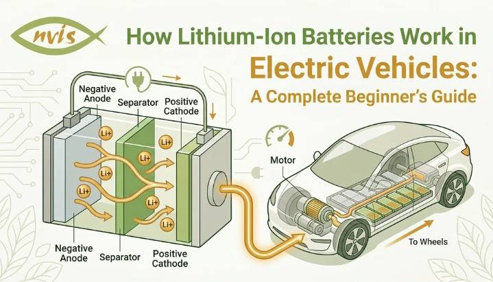
    Cathode Positive Electrode

    The positive electrode of a battery is called cathode. The use of a material in the cathode is also the most critical factor in the character of a battery, that is, its energy density, thermal stability, cost and cycle life. On the cathode side of EV lithium ion batteries, the three most popular compounds are lithium iron phosphate (LFP), lithium nickel manganese cobalt oxide (NMC), and lithium nickel cobalt aluminum oxide (NCA). There are different proportions of properties in each chemistry. LFP has less energy density, but is more thermally stable and has a longer service life. Greater energy density (more driving range) but more careful thermal management with NMC. The selection of the cathode material is the most critical one that the battery designer has to make. During discharge, lithium ions move from the anode to the cathode through the electrolyte, while electrons flow through the external circuit to power the vehicle.

    Anode Negative Electrode

    Anode is a negative electrode and acts as a lithium storage site during charging. In almost all present EV lithium ion batteries, the anode is fabricated of graphite, which is a layered carbon-based material that contains a structure capable of fitting lithium ions in between the layers, known as intercalation. In charging, the lithium ions pass from the cathode, through the electrolyte, and into the graphite anode where they become stored. During discharge, lithium ions move from the anode to the cathode through the electrolyte, while electrons flow through the external circuit to power the motor. Today it is the industry standard, but research is actively underway on silicon-graphite blend anodes that could greatly increase the amount of lithium that can be stored in each anode, and thus the energy density without adding weight.  

    Electrolyte Ion Highway

    The electrolyte is the medium through which lithium ions travel between two electrodes. In current EV lithium ion batteries, electrolyte is typically a liquid made from lithium salts dissolved in an organic solvent. This liquid allows ions to move freely between cathode and anode while not conducting electrons meaning electrons must take an external circuit route, which is what creates usable electrical current. The electrolyte is a critical determinant of a battery’s operating temperature range, charging speed, and safety characteristics. It must remain stable across a wide voltage window and resist breaking down under thermal and electrochemical stresses of EV operation. One of the key reasons liquid electrolytes are a safety concern  in battery fires is that many organic solvents are flammable which is why next-generation solid-state batteries aim to replace liquid electrolyte with a solid ceramic or polymer material.

    Separator Safety Barrier

    A separator is a thin, porous membrane placed between cathode and anode. Its job is simple but critical: prevent two electrodes from making direct contact (which would cause a short circuit) while allowing lithium ions to pass through its pores. One important safety feature of modern separators is that their pores close at high temperatures. If a cell begins to overheat, this automatic pore-closing shuts down ion transport and acts as an internal thermal fuse, helping prevent runaway heating from escalating into a fire.

    How Does a Lithium Ion Battery Work? Charging and Discharging Explained

    Now that four components are clear, the working principle of a lithium ion battery becomes straightforward to understand. Everything revolves around movement of lithium ions between cathode and anode back and forth, charge after charge.

    Discharging: How Battery Powers Motor

    When you turn on an electric vehicle and press the accelerator, the battery begins discharging. Here is what happens inside each cell at that moment. Lithium ions, which were stored in graphite anode during previous charge, begin migrating through electrolyte toward cathode. As these positively charged ions travel across, they leave behind electrons in anode. Those electrons cannot travel through the electrolyte because the electrolyte is electronically insulating, while the separator prevents direct contact between the electrodes. Instead, they flow out through external circuits through the vehicle’s power electronics, to the electric motor, and back to the cathode. This electron flow is electrical current that drives the motor. The process continues until lithium ions have largely migrated back to the cathode, at which point the battery is discharged and the state of charge is low.

    Charging: Storing Energy Back in Battery

    When you plug an EV into a charger, the process reverses exactly. charger supplies external voltage that pushes lithium ions from cathode, through electrolyte, and back into graphite anode for storage. Electrons are simultaneously driven from cathode to anode through an external circuit by the charger’s voltage. This reversibility is what makes lithium ion batteries rechargeable. Electrochemical reactions at both electrodes are designed to be reversible hundreds to thousands of times without significant structural damage though gradual degradation does occur with each cycle, which is why batteries slowly lose capacity over years of use.

    Regenerative Braking: Recovering Energy in Motion

    Electric vehicles have one significant advantage over conventional brakes: they can recover kinetic energy instead of wasting it as heat. When you lift off the accelerator or apply brakes in an EV, the motor switches to generator mode. The vehicle’s motion drives the motor to generate electricity, which flows back into the battery pack charging it slightly with energy that would otherwise be lost as brake heat. This regenerative braking is managed by EV’s power electronics and coordinated with the battery management system to ensure safe, efficient energy recovery.

    From Single Cell to EV Battery Pack Understanding Architecture

    One of the misconceptions is that the EV consists of one large battery. In fact, an EV lithium ion battery pack consists of multiple individual cells connected to a precisely designed battery architecture that is organized into a layered hierarchy that ensures the desired voltage, capacity and safety margins for driving the vehicle. Most lithium-ion cells have a nominal voltage between approximately 3.2V and 3.7V depending on the chemistry of the cell. This is not enough for a motor controller which works on 300-800 volts. The answer is to string many cells together each cell with its voltage added to the rest. Cells in parallel: Same voltage, greater total current capacity and energy storage. A module is a collection of cells that are bundled together with structural and monitoring systems. A battery pack comprising a thermal management system, high-voltage connectors, electrical protection devices, and a protective casing is then created from multiple modules. For example, Tata Nexon EV is based on a 30-40 kWh battery pack as per the battery variant. The Ather 450X electric scooter has a lesser 2.9 to 3.7 kWh pack that is better suited for city use. Both are lithium ion batteries scaled to vastly different applications. BMS is an important piece that controls the pack voltage, temperature, provides cell balancing, and protects cell voltage from over-charge, over-discharge and thermal extremes. The BMS is a layer of intelligence that is needed to operate large-format batteries in conjunction with the EV lithium ion battery pack.

    Types of Lithium Ion Battery Chemistries Used in EVs

    Not all lithium ion batteries are the same. chemistry of cathode material creates significant differences in performance, safety, cost, and suitability for different applications. Understanding major chemistry types is essential for anyone studying EV engineering.

    NMC Lithium Nickel Manganese Cobalt Oxide

    NMC is one of most widely used chemistries in passenger EVs globally. Its cathode blends nickel, manganese, and cobalt in varying ratios most common being NMC 811 (80% nickel, 10% manganese, 10% cobalt) and NMC 622. Higher nickel content means more energy density and greater driving range, which is why NMC remains the chemistry of choice for premium EVs where range is the primary selling point. The trade-off is that nickel-rich NMC chemistries are more thermally sensitive and require sophisticated cooling systems to remain safe under fast charging or aggressive driving. They are also more expensive, partly because cobalt is a relatively rare and geographically concentrated material with complex supply chain ethics.

    LFP Lithium Iron Phosphate

    LFP uses lithium iron phosphate as cathode material, iron being one of most abundant metals on Earth. This chemistry has a lower energy density than NMC, meaning a larger and heavier pack is needed to achieve the same range. But LFP makes up for this with significant advantages that are especially relevant for India’s EV market. LFP is thermally stable up to around 250 to 270 degrees Celsius before any risk of thermal runaway significantly higher than nickel-rich chemistries. This makes LFP batteries considerably safer, which directly addresses one of biggest consumer concerns about EV adoption in India following fire incidents in 2022. LFP also offers a much longer cycle life typically 3,000 to 6,000 full charge-discharge cycles versus 1,000 to 2,000 for NMC and costs roughly 30% less to manufacture. These advantages have made LFP dominant chemistry for India’s EV market. Tata Motors uses LFP cells in popular models such as the Nexon EV and Tiago EV. Tata Punch EV uses a 40 kWh LFP pack specifically chosen for mass-market affordability and safety. LFP batteries have become one of the dominant EV chemistries globally, and their adoption in India is expected to remain particularly strong given the country’s price sensitivity, high ambient temperatures, and longer expected vehicle ownership periods.  NCA Lithium Nickel Cobalt Aluminum Oxide NCA was the chemistry that Tesla used in many of its early models, particularly in cylindrical 18650 and 2170 cell formats. NCA delivers very high energy density, enabling long ranges that make Tesla’s vehicles stand apart. It achieves this through a high nickel content, with aluminum added for structural stability. However, NCA has lower thermal stability than LFP and remains primarily used in certain long-range EV applications, while many manufacturers are increasingly adopting NMC and LFP chemistries depending on performance and cost requirements.

    Indian EV Battery Landscape What You Need to Know

    India’s battery ecosystem is evolving rapidly, and local operating conditions are strongly influencing battery technology choices. One important factor shaping battery adoption in India is the country’s demanding operating environment. Summer temperatures are extremely high and above 40 degree Celsius all across the country in most of the states and above 45 degree Celsius in states of Rajasthan, Gujarat and Maharashtra. High ambient temperatures cause more degradation of the batteries and the probability of thermal events in the nickel-rich chemistries. LFP chemistry is one of the reasons for its strong traction in India as compared to other countries around the world because of its high thermal stability characteristics. The annual demand for lithium ion batteries in India is expected to grow from 3 GWh in 2020 to nearly 260 GWh in 2030 – a staggering 100-fold rise in the next decade. The technology of the battery is the largest cost of an electric vehicle (EV) (40-50%) and the single largest factor in EV pricing and affordability. The government has declared batteries as a national priority. The scheme for the manufacturing of Advanced Chemistry Cell (ACC) is Production Linked Incentive (PLI) with an objective of building 50 GWh of domestic manufacturing of cell. In India, several companies like Tata Group, Reliance Industries and Exide Energy Solutions will be setting up large-scale battery manufacturing facilities. India has also discovered 5.9 million tonnes of lithium reserves in the Reasi district of Jammu & Kashmir, which could significantly reduce its dependence on lithium imports in the future, but commercial extraction could take several years depending on exploration, environmental approvals, infrastructure development, and economic viability. The supply chain problem is, at the present time, a very real problem. While the majority of the cathode active materials, separator membranes and electrolyte salts for the Indian EV batteries are still being imported, the main source is China, Japan and South Korea. Domestic companies such as Epsilon Advanced Materials (Telangana, Karnataka) and Himadri Specialty Chemicals are trying to develop their Indian manufacturing capacity for cathodes and anodes, but it will take several years for such capability to be established.

    Challenges Facing EV Lithium Ion Battery Technology

    As much as knowing about what they can do, it’s crucial to know what they can’t do – particularly for students who might be developing the next generation of solutions. The most hazardous problem is “thermal runaway.” If a lithium ion cell is damaged, overcharged, or exposed to excessive heat, exothermic reactions can trigger a self-reinforcing increase in temperature known as thermal runaway, potentially leading to fire or explosion. This is mainly because of the EV fire incidents, which prompted the changes in the AIS-156 safety standard in India in 2022. Thermal management is an ongoing research and engineering issue; some of the latest BMS designs, ceramic coated separators and using LFP chemistry are countermeasures. Consumers’ challenges of charging speed and range anxiety are linked. Fast charging charges in a large amount of energy within short periods of time, thus creating heat and stress for the cell structure. The next challenge for battery engineers is to get the battery charged faster, while at the same time not having to sacrifice cycle life. Frequent fast charging can cause degradation of batteries more quickly than slower charging, especially if fast charging takes place at high temperatures or when multiple fast charges occur at high speeds. All lithium ion batteries will deteriorate over time from cycle life and long term degradation. Over time, battery degradation reduces available capacity and driving range. For example, a vehicle that originally delivers 300 km of range may offer noticeably less range after several years of use, depending on operating conditions and battery chemistry.Managing battery degradation will remain an ongoing engineering and user-education challenge. if it can be addressed with intelligent BMS algorithms and user behaviour, and through thermal control. With the increasing penetration of EVs in India, battery packs are starting to reach their end-of-life, and recycling and second-life applications are gaining significance. While a battery incapable of powering a vehicle at performance is no longer fit for use as a vehicle power source, it still has 70-80% of its original capacity – more than enough for stationary grid storage use. The next big engineering and policy challenge in India’s EV ecosystem is building a reverse supply chain to recycle batteries and utilize them for second-life applications.

    Career Opportunities in Lithium Ion Battery Engineering for Students

    If you are studying electrical, electronics, mechanical, or materials engineering in India right now, lithium ion battery for EV domain is one of most direct routes into a high-growth, high-impact career. Battery Technology Engineer is among the fastest-growing and highly sought-after roles in India’s EV sector. Work involves evaluating cell chemistries (LFP, NMC, NCA), designing and validating battery packs, developing thermal management systems, and ensuring compliance with safety standards like AIS-156, AIS-038, and UN ECE R100. According to industry data, Battery engineering roles often command a salary premium due to growing demand and a shortage of specialized talent, reflecting genuine scarcity of qualified talent. The career pathway includes working on the lab testing side as a Battery Research Associate, then as a Battery Systems Engineer for pack development and BMS integration, and finally as a Battery Technology Specialist and Chief Battery Technologist for innovation in gigafactory scale. Compensation varies significantly based on company, location, specialization, and experience, but battery engineering roles generally offer competitive salaries due to strong industry demand. Advanced R&D and functional safety roles may exceed ₹35 LPA depending on expertise and responsibilities. Employers seek candidates with proficiency in electrochemistry basics, thermal management system design, battery modeling using MATLAB/Simulink, battery modeling algorithm development in Python or C, CAD skills for pack structural design and understanding of safety standards and testing procedures. Students who have done the fundamental coursework in engineering along with doing some projects (even small scale lithium ion pack projects with BMS controller) and get an internship from companies like Tata AutoComp, Log9 Materials, Exicom, Ather Energy or Amara Raja are well equipped to get into this field. Active efforts are being made to establish battery engineering teams by companies like Tata Motors, Mahindra Electric, Ola Electric, Ather Energy, Bosch India, Exide Energy Solutions, Log9 Materials, Reliance Industries (New Energy) and joint ventures being set up around India’s upcoming gigafactories. Bengaluru, Pune, Chennai and Delhi NCR corridor are primary hiring hubs. The programs with accreditation from ASDC (Automotive Skills Development Council), NSDC and AICTE have good recognition among the automotive employers in India for both certification and structured learning. IIT Madras offers courses on EV and battery technologies, IIT Delhi has similar courses and IISc Bengaluru is a research centre for battery materials and energy storage.

    Conclusion

    A lithium ion battery is not just a component inside an electric vehicle. It is technology reshaping how India moves and how Indian engineers, entrepreneurs, and policymakers think about energy security, clean transportation, and industrial competitiveness. Understanding how a lithium ion battery works from movement of ions between cathode and anode, to architecture of a full EV pack, to differences between LFP and NMC chemistry gives you the foundation to engage meaningfully with every conversation in EV space. Whether you are designing battery packs, developing BMS algorithms, writing policy briefs, or simply evaluating your next vehicle purchase, this knowledge matters. India’s lithium ion battery market continues to grow rapidly, supported by government initiatives such as FAME and PLI programs, domestic manufacturing investments, and rising EV adoption. PLI for Advanced Chemistry Cells, domestic gigafactory investments, and the sheer scale of EV adoption that is already underway. The engineering talent gap in battery technology is real and it represents an open door for students who are willing to build deep expertise now. Start with first principles. Build a small project with lithium ion cells and a BMS board. Follow what Tata Agratas, Reliance, and Log9 are building. Understand why India is shifting to LFP. And position yourself for one of the most consequential engineering specializations of the next decade.

    FAQs

    Tags: Lithium-Ion Batteries Work

    EV Battery Life Cycle Explained: Factors Affecting How Long Your Battery Lasts

    TL;DR

    • This blog is for engineering students, EV owners, and technology learners in India who want to understand EV battery life cycle, what battery cycle life means, what degrades it, and how to make a battery last longer.
    • Battery cycle life is the number of complete charge-discharge cycles a battery can deliver before its capacity drops to 80% of its original value. This number varies widely by chemistry, temperature, and how the battery is used.
    • Four biggest factors that shorten EV battery cycle life are heat, deep discharging, frequent fast charging, and calendar aging and all four are manageable with the right habits and vehicle technology.
    • LFP chemistry outlasts NMC in cycle count terms by a significant margin (3,000 to 6,000 cycles versus 1,000 to 2,000), which is a major reason Indian EV makers like Tata Motors have shifted to LFP for their mainstream models.
    • When an EV battery drops below 70 to 80% of its original capacity, it is not dead; it still holds strong potential for second-life applications in grid storage, solar backup, and stationary energy systems.

    Each time you charge an electric vehicle, something happens inside the battery pack. Electrons and lithium ions are constantly moving within the battery, and with every charge cycle a small amount of degradation occurs. All batteries have a finite lifespan. The difference between a battery that maintains a strong charge for 12 years and a battery that noticeably drops in charge over the course of four years can be attributed to a few understood engineering and behavioral principles.

    EV Battery Life Cycle is no longer a concern limited to battery engineers. It is of critical importance to all EV buyers who consider buying a Tata Nexon EV vs an Ather 450X, students who are interested in pursuing careers in electric battery technology and all the fleet operators who are trying to calculate the total cost of ownership of electric buses or three wheelers. This guide will tell you what battery cycle life really is, what makes it go bad, how India’s operating conditions impact battery cycle life and how you as an EV owner, engineer or researcher can maximize the usefulness of an EV battery.

    Also read 

    What Is EV Battery Cycle Life?

    The term cycle life might sound technical, but it can be easily understood if you know what exactly a cycle represents.

    One charge cycle is considered to be the discharge of and complete recharge of 100% of the battery’s usable capacity. It doesn’t have to be one session in particular. If you use around 40% of the battery each day and recharge it, it would take approximately 2.5 days to complete one full charge cycle. Math does not happen per trip, but rather through time.

    A battery cycle life is the number of complete cycles that a battery can withstand until the capacity drops to 80% of the battery’s rated capacity. The industry benchmark for determining “end of first life” for an EV battery is 80%. The battery is not dead at this point, but there is a noticeable reduction in range that will have a major impact on driving.

    If you want to compare the numbers, then a lithium-ion NMC battery in a typical passenger EV can last for as many as 1,000 to 2,000 full cycles before it reaches the 80% mark. Under the same conditions, the life of an LFP (Lithium Iron Phosphate) battery, which is also gaining popularity in the Indian EV market, is between 3000 and 6000 cycles. In the case of an EV owner driving one whole cycle per day on average, the NMC pack can end its first life in 3-5 years of heavy use, whilst the LFP pack can last for 8-16 years. In reality, with partial cycles being the norm, these are much longer.

    However, cycle life alone does not tell the full story. But in actual use, an EV battery’s life cycle depends on a combination of variables temperature, charging patterns, depth of discharge and chemistry  that can greatly impact degradation clocks.

    Two Forms of Battery Degradation

    Before exploring what causes degradation, it helps to know that degradation happens in two distinct ways and both are always happening simultaneously, even when a vehicle is parked.

    Cycle Aging

    Cycle aging is degradation caused directly by repeated charging and discharging of the battery. As the lithium ions move from cathode to anode, and back, small changes occur in the structure of the electrodes. As electrolyte reacts with the surface of the anode during charging, a growing layer called Solid Electrolyte Interphase (SEI) is formed on the surface of the graphite anode. This SEI layer, which is essential for the battery to function, becomes thicker through charge and discharge cycles, which eventually removes some of the active lithium from the battery permanently and causes the internal resistance to rise.

    Lithium ion repeated insertion/extraction into/from the electrode material gradually distorts the crystal structure of the electrode material in cathode. This is one reason NMC batteries generally have lower cycle life than LFP batteries, whose iron phosphate crystal structure is inherently more stable and resistant to long-term structural degradation.

    Over many charge-discharge cycles, the battery gradually loses capacity and experiences increased internal resistance, which is most noticeable as the battery holds less energy after each thousand cycles, and the gradual increase in internal resistance causes the battery to deliver power less efficiently, making performance feel weaker under heavy loads. Under hot-load conditions as it loses maximum power.

    Calendar Aging

    Calendar aging is degradation that happens simply because time passes, regardless of how much battery is used. Even an EV sitting in a garage with a full charge will degrade due to constant electrochemical activity at electrode-electrolyte interface.

    The primary driver of calendar aging is the state of charge (SoC) at which a battery is stored combined with the temperature at which it rests. A battery stored at 100% SoC in a hot environment degrades measurably faster than one stored at 50% SoC in a cool space. This is why EV manufacturers typically recommend not leaving vehicles plugged in at 100% for extended periods, and why parking in shaded areas or covered parking is particularly beneficial in Indian summers.

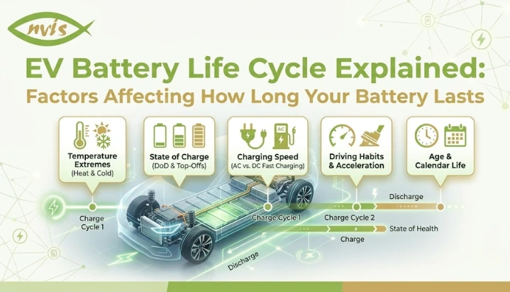
    Together, cycle aging and calendar aging define the total life cycle of an EV battery. key insight is that both processes respond to the same root variables: temperature, state of charge, and discharge depth.

    Key Factors That Affect EV Battery Cycle Life

    No single variable controls EV battery degradation in isolation. The life cycle of an EV battery is a product of how several factors interact over years of use. Understanding each one gives you tools to manage them intelligently.

    Temperature Biggest Threat to Cycle Life

    Temperature is one of the most consistent and significant factors impacting battery life. Lithium-ion batteries perform best between 20 and 40 °C. High and low exposures for extended periods increase calendar aging and cycle aging.

    The higher the temperature, the faster the electrochemical reactions at the cell surfaces, which leads to faster SEI layer growth and the consumption rate of active lithium in parasitic side reactions. Beyond 45℃, the rate of capacity loss increases significantly. This is especially a problem in India, where in summer, ambient temperature in Rajasthan, Gujarat and Madhya Pradesh is regularly above 45°C and vehicles are kept outside for long periods.

    Low temperatures are another problem. Cold has a huge impact on slowing lithium ion movement in the electrolyte, which means less power and charging speed. Worse yet, however, charging at lower temperatures, particularly at high rates, can lead to the formation of metallic lithium on the surface of the anode (lithium plating) in place of the intercalation of clean lithium. Lithium plating is an irreversible loss of active lithium capacity and is permanent. Plating can reduce the charging speed of EVs especially in low temperatures, and the BMS will do its best to avoid plating.

    Thermal management (usually a liquid cooling circuit in four-wheelers and forced air cooling in scooters) is a key factor in the efficiency of real-world battery life, especially in India’s climate.

    Depth of Discharge How Low You Go

    Depth of Discharge (DoD) is the percentage of the battery’s capacity used in each charging cycle. A 100% DoD cycle involves fully discharging the battery from full to empty, and then recharging it back to full. 50% DoD cycle will involve using half of the battery charge during each discharge session.

    DoD and cycle life are strongly and non-linearly related. Batteries discharged shallowly, survive many more cycles than batteries discharged deeply repeatedly. Laboratory studies show that shallow cycling can significantly increase cycle life, whereas batteries repeatedly cycled at 80–100% DoD may reach the 80% capacity threshold after only 500–1,000 cycles.

    That’s why EVs don’t ever allow you to use 0% to 100% of the nominal battery capacity. Battery Management System has room at either end and a protected floor below 0%, and a ceiling above 100%, so that the battery is always in a shallower DoD than it appears. In reality this means that most users who do not push their battery to extremes will experience better real world cycle life than a rated specification.

    Shallow cycling is generally beneficial for battery life and is common among Indian urban commuters, who charge from home mainly at night and seldom let their batteries drop below 20% battery health.

    Charging Speed Fast Charging Trade-off

    One of the hot debates on EV battery longevity is fast charging. 20-30 minutes charging with a DC fast charger is comparable to what you can achieve in a few hours charging from an AC Level 2 home charger convenience is real. The downside is that faster charging places greater stress on the battery.

    The principle of fast charging is to charge a far greater current into the battery within a short period of time. This fast charging rate in battery terms is known as C-rate and creates more heat at the electrode surfaces and causes more lithium ions to be pushed into the graphite anode during the fast charging than slow charging does. The possibility of incomplete lithium insertion increases under high C-rate, leading to an increased risk of lithium plating, especially at low temperatures or when the battery is already partially charged.

    Studies indicate that frequent DC fast charging from a low state of charge (SoC) to 100% is more stressful than slow charging. Several studies have shown that frequent ultra-fast charging can accelerate degradation compared with slower AC charging, although the impact varies by battery design and operating conditions when compared to home charging at the same total energy throughput. The reason your EV may take longer to charge than the fast charger’s maximum charging rate indicates is because the BMS is likely to restrict the flow of current from the fast charger so as not to put excessive stress on the battery.

    In case of LFP batteries, the fast charging is much less damaging because the crystal structure of the cathode material is much more stable. This is another aspect of LFP Chemistry which is practically beneficial for Indian EV users when they go long-distance journeys and depend on public fast charging stations.

    A general rule that comes from battery science is simple: Slow level 2 AC charging at home for everyday driving; fast DC charging on long trips where time really counts.

    State of Charge Storage Idle Risk

    Even when the car is parked, electrochemical reactions continue inside the battery. If a battery is held at a very high or very low SOC for a long time without cycling, degradation will still occur.

    High SoC (e.g. charging battery to 100 per cent or close to it overnight for days at a time) keeps the cathode in a chemically stressed high voltage state. With high SoC storage for a longer period of time, the rate of electrolyte oxidation at the cathode surface will accelerate and the capacity fade rate in NMC chemistry will increase. Very low SoC storage can cause copper dissolution and increase the risk of internal short circuits if cell voltage falls too low in severe cases resulting in copper dissolution and internal short circuit risks.

    Battery engineers suggest that a SoC of approximately 40 to 60% is the best range for storing batteries for a long time. Maintaining 80% charge level for most NMC-based EVs is a good balance for everyday driving, avoiding the extremes of 20% and 100%. Unlike NMC chemistry, which is more sensitive to being charged to 100%, Many manufacturers recommend periodically charging LFP batteries to 100% to improve state-of-charge calibration, though daily charging recommendations vary by vehicle model to improve state-of-charge calibration, though daily charging recommendations vary by vehicle with LFP packs because the upper voltage limit of LFP is lower and less stressful than NMC.

    EV Battery Cycle Life in India A Different Challenge

    India presents a unique combination of conditions that affect the life cycle of an EV battery in ways that differ from European or North American markets. Understanding this context is important for students, engineers, and policy researchers working in India’s EV space.

    Thermal is the most important one. During summers the temperature in most parts of India goes above 40°C and in Jaipur, Ahmedabad and Indo-Gangetic plains reaches above 45°C frequently. These are exactly the temperatures where nickel-rich NMC chemistry fails to cycle as well as it should, and needs additional liquid cooling to achieve good cycle life. This attribute of LFP chemistry offers significantly better thermal stability than NMC chemistry, makes it highly tolerant for the ambient heat conditions in India, a major reason for its supremacy as chemistry for Indian EVs.

    This is evident from a comparison of EV models available in India. Models based on the NMC chemistry, such as the MG ZS EV and the Mahindra XUV400, depend on the use of an active liquid cooling system to get to their rated cycle life in Indian conditions. Real-world data from LFP-equipped EVs generally shows low degradation during the first few years of ownership, though long-term performance varies by usage conditions in India, especially in hot climates. LFP-based batteries such as BYD’s Blade Battery are widely recognized for their thermal stability and suitability for hot-climate operation.contributing to strong performance in Indian operating conditions.

    Yet another contributing factor in India is traffic congestion. The thermal load of the battery from stop-and-go driving is higher than on the highway, and it results in more regenerative braking cycles. Urban EVs in cities such as Mumbai/ Delhi have more partial cycles per day as compared to the EVs used mostly on highways which is good for cycle life but comes with a challenge in the thermal management space.

    India’s warranty standards are reflective of this reality. The majority of EV manufacturers in India provide warranties that last anywhere from 8 years to 1,60,000 km to 2,00,000 km with a minimum capacity retention of 70 to 80% during the warranty period. Tata Motors has taken the extra step with the Curvv EV and Nexon EV 45 kWh, which is a testament to the confidence it has in the performance of LFP chemistry in Indian conditions as it offers a lifetime battery warranty for eligible first private owners, subject to manufacturer terms and conditions.

    How Battery Management System Protects Cycle Life

    Battery Management System is not just a monitoring tool it is the primary mechanism through which EV manufacturers protect EV battery life cycle in real-world operation.

    Every BMS enforces operational boundaries that prevent most damaging behaviors from occurring. It sets a charge ceiling below the battery’s physical maximum, ensuring cells are never stressed at highest voltage states. It sets a discharge floor above true empty, preventing deep discharge damage that would otherwise shorten cycle life dramatically. It adjusts maximum charging current based on real-time temperature readings, slowing down DC fast charging in cold weather to prevent lithium plating, and capping charge power in high-heat conditions to prevent thermal acceleration of SEI growth.

    Modern BMS systems also implement cell balancing ensuring that every individual cell in a pack remains at the same state of charge. Over time, cells develop slight performance differences due to manufacturing variation and non-uniform temperature exposure within the pack. Without balancing, the weakest cell limits the entire pack’s performance, and the rest of cells are either overcharged or undercharged relative to their individual capacities. Balancing extends usable pack life by ensuring no single cell becomes a bottleneck.

    OTA (Over-the-Air) software updates have added a new dimension to BMS capability. Manufacturers like Tata Motors and Ather Energy now push BMS algorithm improvements directly to vehicles in the field, refining SoC estimation accuracy and adjusting thermal management parameters based on accumulated fleet data. This means the BMS protecting your battery in year five may be significantly smarter than the version originally shipped with the vehicle.

    What Happens at End of First Life Second Life and Recycling

    When the SoH of a battery is at 70-80% level, it is no longer optimal for an EV, since the latter demands minimum performance levels based on the range expected. However it is not totally useless.

    A retired EV battery has a considerable amount of energy storage left and can be used for stationary energy storage for 10-15 years at 70-80% of its original capacity. Second-life battery applications is the idea and it’s an emerging area of significance to India’s circular economy.

    Depending on chemistry and remaining SoH, second-life applications may help recover part of a battery’s residual value, potentially reducing overall ownership costs.

    In India, startups such as LOHUM Cleantech, Attero, Nunam and BatX Energies are developing businesses in the field of second life batteries with the support of India’s Battery Waste Management Rules 2022, which have established Extended Producer Responsibility (EPR) frameworks, mandating OEMs and battery manufacturers to collect and process end-of-life batteries. India’s lithium-ion battery recycling volumes are growing rapidly as more EV batteries approach end-of-life, creating significant opportunities for recyclers and material recovery companies with the increasing number of first-generation EVs reaching their battery replacement stage.

    Once batteries can no longer be reused, valuable material is recovered within the lithium, cobalt, nickel, manganese and copper of batteries. Cells are chemically dissolved in recycling processes such as hydrometallurgy, with recovery rates of 95% or more, in order to be used for producing new cells. This completes the EV battery life cycle, enabling the recycling of end-of-life batteries into raw material for future EV batteries.

    Practical Tips to Extend EV Battery Cycle Life

    Knowing the science behind battery degradation is very much the knowledge that leads to actionable habits that prolong EV battery life. These suggestions are valid for EV owners in India only for thermal and usage context.

    For everyday use, maintain 20-80% state of charge. In the case of NMC batteries, it’s the one behavioral change that has the biggest impact on battery life. Within this medium range, full charge doesn’t cause high voltage stress or deep discharge causes low voltage damage. Regularly charging NMC batteries to 100% generally accelerates long-term degradation compared with limiting daily charging to lower levels. Many manufacturers recommend periodically charging LFP batteries to 100% for calibration purposes, although daily charging recommendations vary by vehicle model, because the nominal voltage is much lower, resulting in much lower stress during charging to 100%.

    Opt for home Level 2 charging over DC fast charging for daily use. AC charging is slower, less intensive, produces less heat and provides BMS with sufficient time to balance cells during the charging process. Avoid using a DC fast charger if it isn’t a long highway trip.

    During the hot season in India, park in the shade or under a cover. One of the quickest ways of calendar aging is to subject the battery to thermal stress, particularly at high SoC. A battery which is fully charged (SoC-90%) in the summer of 48° in Jaipur will lose its capacity much more quickly than another battery at 50% SoC in a covered parking area.

    Don’t miss out on OTA software updates. BMS firmware updates are made regularly to enhance the accuracy of SoC estimates and optimize charging algorithms, while also adding in enhancements to the thermal management. Maintaining the software of a vehicle is among the simplest to most effective maintenance steps for the battery’s health.

    If your EV has a battery preconditioning feature, take advantage of it. Tata Nexon EV and BYD Atto 3 models come with a feature that allows the batteries to warm or cool them to an optimum temperature before charging, which is helpful before using a DC fast charger in winter or during extremely hot summer afternoons. The use of preconditioning decreases the risk of lithium plating in cold conditions and decreases heat-induced stress in hot conditions.

    Career Opportunities in EV Battery Lifecycle Engineering

    Battery lifecycle management and degradation analysis have created a new engineering specialization with promising job prospects in the booming EV sector in India.

    Battery Degradation Engineer roles focus on modelling the battery degradation according to various usage patterns, creating algorithms that measure remaining useful life (RUL) and testing these algorithms against actual fleet data. The Battery Validation and Test Engineer positions are geared towards the specification and testing of accelerated aging tests for cells and packs that are exposed to high temperatures, deep discharge cycles and fast charging stress to determine degradation characteristics prior to customer delivery.

    Second-life battery engineering is still a nascent field in which engineers evaluate used battery packs, classify them based on their remaining SoH, configure modules to be used in stationary applications, and develop testing protocols and safety standards for second-life systems. The battery recycling process engineering is also expanding, with battery recycling corporations increasing the capacity of their hydrometallurgical processing and recruiting chemical engineers and electrochemists who have experience in the battery sector.

    Employment skills needed for battery lifecycle positions include knowledge of electrochemistry fundamentals, Python or MATLAB programming skills, understanding of BMS data protocols (CAN bus, OBD-II), and experience with battery cycling equipment such as cyclers and impedance analyzers, including the ability to perform accelerated aging testing per IEC 62660 and AIS-156.

    The Battery Waste Management Rules, 2022 have brought about compliance requirements throughout the value chain, and thus, there is an increased demand for EPR (Extended Producer Responsibility) program management jobs for OEMs, battery manufacturers, and specialized battery recycling companies. With the rising adoption of EVs and strict end-of-life battery policies across the world, The global EV battery recycling market is expected to hit USD 25 billion by 2025 and reach nearly USD 88 billion by 2032, growing at a CAGR of more than 19%.

    Battery lifecycle is a truly interdisciplinary and future-proof domain, which Indian engineering students can specialize on given its mechanical, electrical, chemical engineering aspects.

    Conclusion

    EV battery life cycle is not a predetermined number that appears on a spec sheet. It is a dynamic result affected by chemistry, thermal conditions, charging behaviour, depth of discharge and quality of protection of the pack by Battery Management System. The knowledge of these factors can put EV owners in a position to meaningfully prolong the useful life of their battery, provide tools for engineers to design the next generation of EV batteries and provide a clear path forward of the most impactful technical challenges that still need to be resolved.

    The transition to LFP chemistry for EVs in the mainstream market is one of the biggest technology choices made in the last couple of years, in particular for India. In India, where the summers are hot, LFP’s longer cycle life, superior thermal stability and lower sensitivity to temperature make it much more predictable and promising to use the life of an EV battery in Indian conditions as compared to NMC chemistry without substantial investment in thermal management.

    The first life of a battery isn’t the end of the line. The expanding second-life battery ecosystem under the Battery Waste Management Rules, EPR and start-ups developing infrastructure for recycling makes it important for engineers involved with stationary battery storage as well as battery recycling specialists to understand battery lifecycle management.

    As a student interested in this area, get your feet wet and learn the basics: learn what cycle life is, learn about four major degradation factors, and develop technical expertise in battery testing, BMS data analysis, or electrochemical modeling. The demand for engineers who have the in-depth knowledge of EV battery life cycle, from initial charging to its second life and finally to recycled raw material is on a rise both in India and around the world and this will continue in the foreseeable future.

    FAQs

    EV battery cycle life is the number of complete charge-discharge cycles a lithium-ion battery can complete before its usable capacity falls to 80% of its original rated value. For NMC batteries used in most passenger EVs, typical cycle life is 1,000 to 2,000 full cycles. For LFP batteries, which are increasingly common in Indian EVs, cycle life is 3,000 to 6,000 full cycles. Real-world cycle life depends heavily on temperature, charging habits, and depth of discharge.

    In India, EV batteries typically last 8 to 12 years under real-world conditions, depending on chemistry, local climate, and charging behavior. Global estimates go up to 15 years in moderate climates, but India’s high summer temperatures can accelerate degradation in NMC batteries if thermal management is inadequate. Most Indian EV manufacturers offer battery warranties of 8 years or 1,60,000 to 2,00,000 km, guaranteeing at least 70 to 80% capacity retention during that period.

    Yes, but impact depends on frequency and conditions. Frequent DC fast charging generates additional heat and can accelerate battery degradation compared to slower AC charging, although the exact impact depends on battery chemistry, thermal management, and charging conditions. LFP batteries are considerably more tolerant of fast charging due to their more stable cathode chemistry. Using DC fast chargers occasionally for long trips while relying on Level 2 home charging daily is recommended practice for NMC battery owners.

    Cycle aging is degradation caused by charge-discharge cycles every time battery charges and discharges, small structural changes accumulate in electrode materials. Calendar aging is degradation that happens over time regardless of use, driven primarily by temperature and state of charge at which battery is stored. Both forms of aging always occur simultaneously, and both are accelerated by high temperatures and high states of charge during storage.

    When an EV battery drops to 70 to 80% of its original capacity and is no longer suitable for primary vehicle use, it enters a second life phase rather than being discarded. Second-life EV batteries are repurposed for stationary energy storage applications grid balancing, solar backup, telecom tower power, and home energy storage where lower capacity is not a constraint. In India, startups like LOHUM Cleantech, Attero, Nunam, and BatX are building second-life battery businesses. After second life, cells are recycled using hydrometallurgical or pyrometallurgical processes to recover lithium, cobalt, nickel, and other materials for reuse.

    most effective practices for extending EV battery life cycle in Indian conditions include: keeping daily charge between 20 and 80% for NMC batteries (LFP batteries can be charged to 100%); preferring AC Level 2 home charging over DC fast charging for daily use; parking in shade or covered parking to minimize heat exposure during summer; keeping software updated so BMS benefits from manufacturer improvements; and using battery preconditioning feature before DC fast charging sessions when available. Avoiding prolonged storage at high SoC in hot weather is especially important for Indian summers.

    Tags: EV Battery Life Cycle

    Speed Control of PMSM Motor: A Complete Beginner’s Guide for Engineering Students

    TL;DR

    • This blog is for engineering students, freshers, and EV enthusiasts who want to understand how speed control of PMSM motors works and why it is central to modern electric vehicles and industrial drives.
    • A Permanent Magnet Synchronous Motor (PMSM) does not control its own speed automatically; it needs an intelligent controller to regulate how fast it spins, depending on load and application demands.
    • The three most commonly discussed speed control techniques for PMSM motors are Scalar Control (V/Hz), Field-Oriented Control (FOC), and Direct Torque Control (DTC), each suited to different performance and precision requirements.
    • Field-Oriented Control (FOC) is industry gold standard for PMSM motor controllers in electric vehicles because it delivers high efficiency, smooth torque, and precise speed tracking across a wide operating range.
    • India’s booming EV sector from e-rickshaws to premium four-wheelers is driving massive demand for engineers who understand PMSM motor control, making this one of most career-relevant topics in electrical and electronics engineering today.

    Electric vehicles were once considered a distant future. Today, they are parked outside engineering colleges, running on Indian highways, and being manufactured in cities like Pune, Chennai, and Bengaluru. At the heart of nearly every modern EV sits a Permanent Magnet Synchronous Motor and behind that motor sits a sophisticated speed control system that makes smooth acceleration, efficient cruising, and controlled braking possible.

    If you are studying electrical engineering, power electronics, or mechatronics, understanding speed control of PMSM motors is not just an academic exercise. It is a foundational skill that connects directly to one of the fastest-growing industries in the world.

    This blog breaks down everything you need to know from what a PMSM is, to how different control methods work, to where India stands in this technology landscape and what opportunities await you as an engineering graduate.

    Also Read,

    What Is a PMSM Motor and Why Does It Need Speed Control?

    Before you can understand speed control, you need to understand what makes a PMSM different from a regular motor and why controlling its speed is not as straightforward as it might seem.

    A Permanent Magnet Synchronous Motor has two key parts: a stator (stationary outer section) and a rotor (spinning inner section). The rotor is fitted with permanent magnets instead of electromagnets or copper windings. When alternating current flows through stator windings, it creates a rotating magnetic field. The rotor’s permanent magnets lock on to this rotating field and spin along with it which is why it is called a “synchronous” motor. The rotor always spins at the same speed as the rotating magnetic field, no more, no less.

    Now here is a problem. If the rotor spins in perfect sync with the supply frequency, how do you change its speed? short answer: by changing frequency and magnitude of AC supply fed to stator. But doing this in a way that keeps the motor efficient, stable, and responsive across different loads is the entire challenge of PMSM speed control.

    A PMSM does not self-regulate.Without an appropriate control system, a PMSM cannot reliably maintain desired speed and torque under changing operating conditions and may lose synchronism under varying loads. The PMSM motor controller is a brain that constantly monitors what motor is doing and adjusts electrical input to keep speed and torque exactly where you need them.

    Think of it like cruise control in a car. The driver sets a speed, and the system continuously adjusts fuel delivery to maintain that speed whether the road is flat or uphill. A PMSM controller does the same thing for a motor except it works thousands of times per second.

    What Is a PMSM Motor? Key Characteristics That Make It Special

    PMSM stands apart from induction motors and DC motors for reasons that directly matter to real-world performance.

    High Power Density: A PMSM produces more power per kilogram of motor weight compared to most other motor types. For electric vehicles where every gram of weight affects range, this is a critical advantage.

    High Efficiency: PMSM efficiencies typically range between 92% and 97%, making them an excellent choice for EV applications where battery energy must be used as judiciously as possible.

    Wide Speed Range: PMSM motors maintain high efficiency across a broad range of operating speeds from near-zero to well above rated speed. This suits EV driving profiles, which constantly shift between slow traffic, highway cruising, and regenerative braking.

    Torque at Low or Zero Speed: With an appropriate controller such as FOC, a PMSM can produce rated torque at standstill or very low speeds. This makes it suitable for applications requiring smooth startup and precise control.

    Low Maintenance: With no brushes or slip rings, PMSM motors have fewer mechanical parts that wear out. This reduces long-term maintenance costs, which is important for commercial EV fleet operators.

    These characteristics explain why manufacturers like Tesla (Model 3), BYD, and Indian EV companies increasingly favor PMSM motors in their drivetrains. Tesla Model 3 uses a PMSM-based drive system that combines high efficiency, compact packaging, and advanced motor control strategies to achieve strong performance and long driving range.

    Three Core Methods of Speed Control of PMSM Motor

    Not all PMSM applications need the same level of precision. A simple conveyor belt has very different requirements from a high-performance EV drivetrain. This is why engineers have developed multiple speed control strategies, each with its own trade-offs between simplicity, performance, and cost.

    1. Scalar Control (V/Hz Control) Simple Starting Point

    Scalar control is primarily used with induction motors. Although it can be applied to PMSMs in certain low-performance applications, it is generally unsuitable for high-efficiency PMSM operation because PMSMs require accurate rotor position synchronization and torque control, PMSMs generally require more advanced control techniques such as FOC for stable and efficient operation. The basic idea is simple: since rotor speed depends on frequency of AC supply, you change speed by changing supply frequency. To prevent the motor from losing too much magnetic flux (which would reduce torque), you also scale voltage proportionally hence the name V/Hz (Volts per Hertz) control.

    Imagine turning up a fan speed by simply increasing voltage and frequency of power supply. That is essentially what scalar control does. It is easy to implement, inexpensive, and works well in applications where load remains relatively constant and precision is not critical such as basic pumps, fans, and simple conveyor systems.

    However, scalar control has significant limitations for PMSM motors in demanding applications. It cannot independently control torque and flux. It responds slowly to sudden load changes. It does not use real-time feedback from the motor, meaning it operates essentially blind. For EV applications, where load conditions change every fraction of a second, scalar control is simply not good enough.

    2. Field-Oriented Control (FOC) Industry Standard for PMSM Controllers

    Field-Oriented Control, often called FOC or vector control, is a technique that transformed PMSM motor control from a complex academic challenge into a practical engineering solution. Understanding FOC is essential for anyone working with PMSM motor controllers in modern systems.

    Here is core intuition. A DC motor is easy to control because its magnetic flux and torque are produced by separate, independent current paths. You can increase torque without disturbing flux, and vice versa. An AC motor like a PMSM does not naturally work this way; all three phase currents interact with each other in a rotating reference frame, making independent control of torque and flux seemingly impossible.

    FOC solves this by using mathematical transformations, specifically Clarke and Park transformations to look at motor’s rotating currents from a different reference frame. By transforming three-phase currents into two orthogonal components called d-axis current (flux-producing) and q-axis current (torque-producing), FOC effectively turns a complex three-phase AC motor into something that behaves like a simple DC motor. Torque and flux can now be controlled independently, in real time, with high precision.

    Clarke transformation converts three-phase (a, b, c) quantities into a two-phase stationary reference frame. Park transformation then converts those into a rotating d-q reference frame aligned with the rotor. Once in the d-q frame, two simple PI (Proportional-Integral) controllers handle rest. After computing required voltages, an inverse Park and Clarke transformation converts everything back to three-phase signals, which then drive the motor through a PWM inverter.

    FOC ensures optimal speed and torque control even at very low speeds something scalar control cannot achieve. It automatically compensates for changes in motor load, speed, or operating direction. And it does all of this while keeping efficiency as high as possible, a critical requirement for a PMSM motor for EV applications where every watt matters.

    For EV applications specifically, FOC research conducted using Indian Drive Cycle (IDC) a speed-time profile simulating real Indian traffic conditions has confirmed that FOC-based PMSM control delivers superior performance for vehicles like e-rickshaws and electric scooters. Indian researchers at institutions including NIT Meghalaya and Rajiv Gandhi Institute of Technology, Kottayam, have published significant work on this exact application.

    ParameterScalar ControlField-Oriented Control (FOC)
    Torque-Flux DecouplingNoYes
    Dynamic ResponseSlowFast
    Low-Speed PerformancePoorExcellent
    ComplexityLowMedium-High
    EV SuitabilityNoYes
    Cost of ImplementationLowMedium

    3. Direct Torque Control (DTC) Speed Through Torque

    Direct Torque Control takes a different approach to speed control of PMSM motors. Instead of controlling speed by regulating currents through a rotating reference frame like FOC does, DTC controls speed by directly and continuously selecting an inverter switching state that produces the closest match to desired torque and flux.

    DTC is faster in torque response than FOC and does not require complex coordinate transformations. However, it tends to produce more torque ripple slight fluctuations in torque output that can cause vibration and noise. For applications like high-precision servo drives or very smooth EV driving experiences, this ripple is a disadvantage. Modern DTC implementations use improved switching strategies to reduce ripple, but FOC remains the dominant choice for PMSM-based EV drivetrains.

    How a PMSM Motor Controller Actually Works

    Now that you understand speed control methods, let us trace how a complete PMSM motor controller functions in a real system step by step.

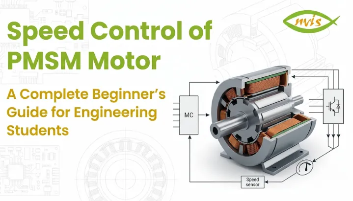
    Step 1 Speed Reference Input: driver (or automated system) provides a desired speed. In an EV, this comes from the accelerator pedal position sensor.

    Step 2 Speed Measurement: A sensor typically an encoder, resolver, or Hall effect sensor measures actual rotor speed and position in real time.

    Step 3 Speed Error Calculation: controller compares desired speed to actual speed. The difference is called speed error.

    Step 4 Torque Reference Generation: A PI controller uses speed error to calculate how much torque motor needs to generate to close that gap.

    Step 5 Current Control (FOC Specific): torque reference is converted into d-axis and q-axis current references. Inner current control loops then adjust stator voltages to drive actual currents toward these references.

    Step 6 PWM Signal Generation: computed voltage references are used to generate Pulse Width Modulation (PWM) signals. These signals switch inverter’s power transistors (typically IGBTs or MOSFETs) at high frequency to produce required voltage waveform.

    Step 7 Motor Response: motor receives controlled three-phase voltage and current, producing right amount of torque to achieve and maintain target speed.

    This entire loop runs thousands of times per second. The outer speed loop typically runs at a lower sampling rate (say, 1 kHz), while the inner current control loop runs much faster (often 10 kHz or higher). This cascaded structure ensures both speed stability and fast dynamic torque response.

    PMSM Motor for EV: Why It Is Motor of Choice in Electric Vehicles

    A PMSM motor for EV applications is not an arbitrary choice. It is the product of decades of research into what motor technology best matches demanding requirements of vehicle propulsion.

    An electric vehicle motor must produce high torque at low speeds for acceleration from standstill, maintain high efficiency across a wide speed range during normal driving, handle regenerative braking smoothly, fit compactly within a vehicle chassis, and survive years of thermal and mechanical stress. PMSM ticks every one of these boxes.

    In the constant-torque region, where the motor operates below its rated speed, FOC typically increases q-axis current (the torque-producing component) while maintaining an optimal d-axis current reference, enabling Maximum Torque Per Ampere (MTPA) operation and high efficiency.

    In a constant power region when the motor exceeds its rated speed a technique called field weakening is applied. Here, a negative d-axis current is introduced to reduce effective magnetic flux, allowing the motor to spin faster than its base speed without violating voltage or current limits. This is analogous to shifting gears in a conventional car where you trade torque for speed.

    Regenerative braking is another area where PMSM and FOC shine together. When the driver decelerates, the motor switches to generator mode, converting kinetic energy back into electrical energy that recharges the battery. FOC manages this transition seamlessly, without jerks or instability.

    Indian EV manufacturers and research institutions have taken notice. FOC-based PMSM control systems have been validated for e-rickshaw applications under Indian Drive Cycle accounting for India’s specific driving conditions including stop-and-go traffic, low speeds, and frequent load changes from passenger numbers. Companies operating in India’s EV ecosystem, from Tata Motors and Ola Electric to smaller EV startups, are building drivetrain systems around PMSM motor controllers that implement exactly these principles.

    Various market studies project strong growth for India’s EV sector through the coming decade, driven by policy support, rising consumer adoption, and investments in manufacturing, represents one of fastest-growing technology markets in Asia. The government’s target of 30% EV penetration by 2030 means motor control engineering is no longer a niche academic specialization, it is a mainstream career track.

    Sensorless Speed Control: Next Frontier

    Traditional PMSM controllers rely on physical sensors, encoders or resolvers to measure rotor speed and position. These sensors add cost, increase system complexity, and can fail in harsh industrial or automotive environments. Sensorless control eliminates this dependency by estimating rotor position mathematically from measurable quantities like back-EMF (voltage generated by spinning rotor itself) and motor current signatures.

    Sensorless control techniques are typically divided into two operational categories. In the medium-to-high speed range, machine model-based methods often estimate rotor position using back-EMF and observer-based techniques, machine model-based methods use mathematical observers like Model Reference Adaptive System (MRAS) to estimate rotor position from back-EMF. At very low speeds (below 10% of base speed), signal injection methods are used instead, since back-EMF is too small to measure reliably.

    For EV applications, sensorless control is particularly attractive because it reduces hardware cost, eliminates a potential failure point, and simplifies mechanical assembly. However, sensorless algorithms must be robust enough to handle dynamic, unpredictable conditions of real-world driving. This remains an active area of research, with Indian institutions contributing meaningfully through publications in IEEE and other international journals.

    Career Opportunities in PMSM Motor Control for Engineering Students in India

    If you are an engineering student reading this, here is a practical question you are probably asking: what does understanding PMSM speed control actually do for my career?

    The answer is more direct than you might expect.

    The electric vehicle industry in India is creating thousands of engineering roles across motor design, power electronics, embedded systems, and control algorithm development. Companies like Tata Motors, Ola Electric, Ather Energy, Bajaj Auto, and numerous EV startups are actively hiring engineers who understand motor control fundamentals.

    A solid grasp of PMSM speed control techniques particularly FOC implementation is directly applicable to roles in EV drivetrain engineering, motor controller firmware development, power electronics design, simulation and validation using MATLAB/Simulink, and embedded control systems development using platforms like TI’s C2000 microcontrollers or NXP’s motor control DSPs.

    Beyond EVs, PMSM motor controllers are used in industrial servo drives, CNC machine tools, wind power generation systems, aerospace actuators, and robotics. skill transfers across sectors. Engineers who can simulate a FOC algorithm in MATLAB, understand dq-axis transformations, and validate results against real hardware are genuinely valuable in today’s market.

    For structured learning, students can explore EV engineering certification programs, online motor-control courses, and industry training platforms covering PMSM control, power electronics, and EV drivetrain systems in EV engineering that cover PMSM field-oriented control, motor controller design, and drivetrain integration with recognition by NEAT AICTE and ASDC. Your university electrical machines and power electronics labs, if equipped with PMSM training systems, are also an excellent place to start hands-on experimentation with V/Hz and FOC speed control techniques.

    Conclusion

    Speed control of the PMSM motor is one of the most consequential areas of modern electrical engineering. It is technology that determines how smoothly your electric scooter accelerates, how efficiently a factory robot positions itself, and how far an EV can travel on a single charge.

    From simple logic of scalar V/Hz control to mathematical elegance of Field-Oriented Control, each technique represents a different answer to the same fundamental challenge: making a synchronous motor respond intelligently to changing demands. FOC, with its ability to independently control torque and flux, has become the dominant solution for PMSM motor controllers in electric vehicles precisely because it delivers high performance without sacrificing efficiency.

    India’s EV revolution makes this knowledge timely and career-relevant. As the country moves toward 30% EV penetration by 2030, demand for engineers who can design, simulate, and validate PMSM control systems will only grow. Understanding these concepts now before you step into your first job gives you a genuine edge.

    If you are an engineering student, start with basics: understand the dq-axis model, simulate a simple FOC loop in MATLAB or Simulink, and experiment with a PMSM training kit if your college has one. Concepts may seem abstract at first, but every hour you invest in understanding PMSM speed control today translates directly into engineering skills that India’s EV industry needs tomorrow.

    Frequently Asked Questions (FAQs)

    The speed of a PMSM depends on the frequency of AC supply to its stator. By varying this frequency using a power inverter and a control algorithm, the motor’s speed can be precisely regulated. The PMSM motor controller continuously measures actual speed, compares it to desired speed, and adjusts stator voltage and frequency to correct any deviation.

    FOC separates torque-producing and flux-producing components of stator current, allowing each to be controlled independently. This enables high efficiency, fast torque response, smooth operation at low speeds, and seamless regenerative braking all of which are critical requirements for PMSM motors for EV drivetrains. Scalar control cannot meet these performance demands, and DTC, while fast, produces more torque ripple.

    Both use permanent magnet rotors, but they differ in their back-EMF waveforms and how they are controlled. A PMSM produces a sinusoidal back-EMF and is driven with sinusoidal currents (typically via FOC), resulting in smoother torque. A BLDC motor produces a trapezoidal back-EMF and is driven with square-wave currents in a six-step commutation pattern, which is simpler but produces more torque ripple. For premium EVs where ride quality and efficiency matter, PMSM with FOC is generally preferred choice.

    Sensored controllers use encoders, resolvers, or Hall effect sensors to measure rotor position and speed. Sensorless controllers use mathematical algorithms to estimate rotor position from motor voltage and current measurements, eliminating need for physical position sensors. Sensorless methods reduce cost and improve reliability but are more complex to implement, especially at very low speeds.

    In FOC-based PMSM control, speed and torque control are cascaded. The outer speed control loop compares desired speed to actual speed and generates a torque reference. inner torque control loop then adjusts stator currents to produce exactly that torque. This cascaded structure allows both precise speed tracking and fast torque response, which is why PMSM motor controllers in EVs can feel both smooth and responsive simultaneously.

    Students with a strong foundation in PMSM speed control can pursue careers in EV drivetrain engineering, power electronics design, embedded motor control firmware development, simulation and testing using MATLAB/Simulink, and industrial servo drive development. In India, companies like Tata Motors, Ola Electric, Ather Energy, and various EV startups are hiring engineers with exactly these skills, and demand is expected to grow significantly as India targets 30% EV penetration by 2030.

    Working Principle of PMSM Motor: A Complete Guide for Engineering Students

    TL;DR

    • This blog is for electrical and mechanical engineering students, EV enthusiasts, and technology learners who want to understand how a PMSM motor works from basic construction to real-world applications.
    • A PMSM (Permanent Magnet Synchronous Motor) runs by locking the rotor’s permanent magnetic field in sync with the rotating magnetic field produced by the stator.
    • The working principle of the PMSM motor relies on electromagnetic interaction, no brushes, no slip rings, no rotor windings, which makes it highly efficient and low maintenance.
    • Unlike induction motors, PMSM rotors run at exactly synchronous speed with zero slip, giving it precise speed and torque control.
    • PMSMs are preferred motor choice for electric vehicles, industrial drives, and robotics and understanding them is increasingly valuable for engineering careers in India and globally.

    Imagine two magnets facing each other. When you spin one, the other naturally follows it trying to stay aligned. That simple idea is at the heart of how a PMSM motor works.

    This blog explains the working principle of the PMSM motor in plain language, from what it is and how it is built, to exactly how it generates torque, what makes it different from other motors, and why it matters in today’s world of electric vehicles and smart drives. Whether you are preparing for exams, exploring career options, or just curious about what powers your EV scooter, this guide will give you a solid, practical understanding.

    Also read,

    What Is a PMSM Motor?

    Before diving into the working principle, it helps to know what we are actually talking about.

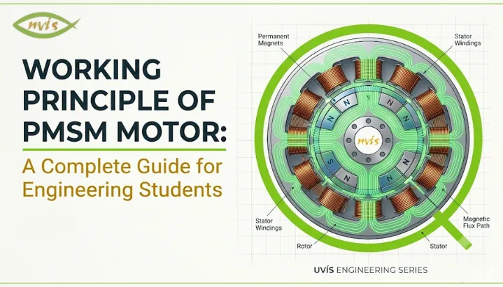
    A Permanent Magnet Synchronous Motor (PMSM) is a type of AC motor where the rotor uses permanent magnets instead of windings or electromagnets to create a magnetic field. stator, on other hand, is supplied with three-phase alternating current that produces a rotating magnetic field.

    The key word here is “synchronous.” The rotor spins at exactly the same speed as the rotating magnetic field of the stator. There is no lag, no slip, two fields are always in lock-step.

    Think of it like two gears perfectly meshed together. One gear (stator field) is driven by electricity. Another gear (rotor) follows it at the exact same rate.

    This synchronous behavior, combined with permanent magnets on the rotor, gives PMSM its signature advantages: high efficiency, compact size, precise control, and minimal energy loss.

    Construction of a PMSM Motor: What Is Inside?

    To understand the working principle of a PMSM motor, you first need to know what it is made of. There are three core parts.

    Stator

    A stator is the outer stationary part of a motor. It contains three-phase copper windings distributed in slots around a laminated silicon steel core. When three-phase AC supply is connected to these windings, they produce a rotating magnetic field (RMF) that sweeps continuously around the stator’s inner circumference.

    This rotating magnetic field is the “driving force” of PMSM. Its speed depends on supply frequency and number of poles in the motor.

    Rotor

    The rotor is the inner rotating part. Unlike a conventional synchronous motor that needs DC excitation through slip rings, PMSM rotor carries high-strength permanent magnets typically made from Neodymium-Iron-Boron (NdFeB) or Samarium-Cobalt (SmCo). These are rare-earth magnets known for their exceptional magnetic strength and thermal stability.

    magnets create a constant, steady magnetic field in the rotor. This is what makes PMSM fundamentally different; no external excitation is needed to maintain the rotor’s magnetic field.

    Based on how magnets are mounted, PMSMs are classified into two types: Surface-Mounted PMSM (SPMSM), where magnets are fixed on the outer surface of the rotor, and Interior PMSM (IPMSM), where magnets are embedded inside the rotor core. The IPMSM variant offers additional reluctance torque and is widely used in EV traction applications.

    Air Gap

    Between the stator and rotor is a small air gap typically just fractions of a millimeter. Magnetic flux passes through this air gap to create interaction between stator and rotor fields. Keeping this gap uniform and tight is crucial for efficiency and performance.

    What Is the Working Principle of PMSM Motor?

    Now comes the most important part in understanding exactly how a PMSM motor generates motion.

    Step 1 Creating Rotating Magnetic Field

    When three-phase alternating current is supplied to stator windings, it creates a magnetic field that rotates continuously. This happens because three phases (R, Y, B) are offset from each other by 120 degrees in time, so their combined effect produces a field that sweeps smoothly around stator circumference.

    The speed of this rotating magnetic field is called synchronous speed (Ns). It is defined by formula:

    Ns = 120f / P

    Where f is supply frequency (in Hz) and P is number of poles.

    For example, at 50 Hz with 4 poles, Ns = 120 x 50 / 4 = 1500 RPM.

    Step 2 Magnetic Field Interaction and Torque Generation

    permanent magnets on the rotor create a constant magnetic field. When the stator’s rotating magnetic field sweeps past the rotor, it interacts with the rotor’s permanent magnetic field.

    According to electromagnetic principles, when two magnetic fields interact with an angular offset between them, a torque is produced. This torque tries to pull the rotor’s magnetic axis into alignment with the stator’s rotating field.

    A good analogy is to imagine a compass needle placed inside a rotating external magnetic field. needle continuously chases external fields, trying to align with it. The rotor in a PMSM does exactly the same, but it “catches up” and locks on, spinning in synchronism.

    Torque is theoretically maximum at a 90° torque angle, but in practical PMSM drives the angle is kept lower to ensure stability and efficient control. This is why precise control of this angle is critical in advanced PMSM drives.

    Step 3 Synchronous Speed Operation and Zero Slip

    Once the rotor locks onto a rotating magnetic field, it runs at exactly synchronous speed. There is zero slip between rotor and stator field.

    This is a key differentiator from induction motors, where the rotor always runs slightly slower than the stator field (slip is necessary for induction to occur). In a PMSM, since the rotor magnetic field is independently created by permanent magnets, no induction is needed and slip is zero.

    This zero-slip property translates directly into stable speed control, better efficiency, and more predictable torque behavior which is why PMSM motors are preferred in servo drives and EV applications.

    Step 4 Electronic Commutation via Inverter

    Unlike a brushless DC (BLDC) motor that uses a trapezoidal back-EMF, a PMSM produces a sinusoidal back-EMF. This means PMSM motors require a sinusoidal current supply, precisely timed and controlled by an inverter (typically a three-phase PWM inverter).

    The inverter adjusts frequency, magnitude, and phase of supply current to control speed and torque of the motor. This is done based on continuous feedback from a rotor position sensor (like an encoder or resolver), which tells the controller exactly where the rotor’s magnetic axis is at any instant.

    This is why PMSM is always paired with an advanced motor controller; it cannot simply be plugged into a direct AC supply way an induction motor can.

    PMSM Motor Working Principle: Role of Field-Oriented Control (FOC)

    Once you understand the basic working principle of the PMSM motor, the natural next step is understanding how it is controlled in real applications.

    The dominant control strategy for PMSMs is called Field-Oriented Control (FOC), also known as vector control.

    Here is the core idea: in a PMSM, total stator current can be mathematically split into two components. First is d-axis current (Id), which controls magnetic flux. The second is q-axis current (Iq), which controls torque production.

    By controlling Id and Iq independently similar to how you separately control voltage and current in a DC motor you get extremely fast and precise control over both speed and torque. This is what enables PMSM motors to accelerate and decelerate with exceptional smoothness, making them ideal for robotics, servo systems, and EV drivetrains.

    d-q transformation (Park’s transformation) is a mathematical tool that converts three-phase rotating currents into these two simplified control components. It is a key topic in power electronics and motor drives courses, and understanding it gives you a real advantage in industries building smart motor systems

    PMSM vs Induction Motor: Key Differences

    A common question engineering students ask is why use a PMSM when induction motors are simpler and cheaper?

    The answer lies in performance demands. Here is a quick comparison:

    Parameter

    PMSM Motor

    Induction Motor

    Rotor Construction

    Permanent magnets

    Copper/aluminium cage windings

    Rotor Excitation

    Not required

    Required (induced)

    Slip

    Zero (synchronous)

    Always present (2-8%)

    Efficiency

    Higher (often above 92-95%)

    Slightly lower

    Power Density

    High compact and lightweight

    Lower for same output

    Speed Control

    Precise, wide range

    Good but less precise

    Cost

    Higher initial cost

    Lower initial cost

    Maintenance

    Very low (no brushes or slip rings)

    Low, but slip rings needed in wound rotor types

    Best Applications

    EVs, servo drives, robotics

    Industrial pumps, fans, general industry

    For applications where energy efficiency, compact size, and precise speed control matter more than upfront cost, PMSM is a better choice. This is exactly why electric vehicles, aerospace actuators, and CNC machines use PMSMs.

    Advantages of PMSM Motors

    Understanding why PMSM motors are so widely adopted helps you appreciate engineering decisions behind modern systems.

    The most significant advantage is high efficiency. Since no current is needed to excite the rotor (magnets do that job on their own), rotor copper losses are eliminated. PMSM motors generally achieve higher efficiency than comparable induction motors because rotor copper losses are eliminated. Under comparable operating conditions, a meaningful difference at industrial scale.

    A compact form factor is equally valuable. High-strength rare-earth magnets create intense magnetic flux in a small volume, allowing PMSM motors to deliver high torque and power from a much smaller and lighter frame than conventional motors. This is critical in EVs, where every kilogram matters for range.

    PMSM motors can generate rated torque at zero speed when controlled by an appropriate inverter and motor drive, which makes them ideal for traction applications where high starting torque is required without need for additional starting circuits.

    absence of brushes, commutators, and slip rings results in significantly lower maintenance requirements and longer operational life, an important consideration for industrial deployments running 24/7.

    Finally, sinusoidal current supply results in smooth, ripple-free torque production, which reduces vibration and acoustic noise particularly valued in robotics and medical equipment.

    Applications of PMSM Motors in India and Globally

    The PMSM motor is no longer limited to specialty applications. It is now found across sectors, and its presence in India is growing rapidly.

    Electric Vehicles

    The single biggest driver of PMSM adoption worldwide is the EV industry India’s EV market has experienced rapid growth in recent years, driving increasing demand for high-efficiency traction motors such as PMSMs., with two-wheelers and three-wheelers commanding over 93% of that volume. Indian motor and powertrain manufacturers are actively developing PMSM-based solutions for electric two-wheelers, three-wheelers, commercial vehicles, and industrial applications and other Indian powertrain manufacturers are actively producing PMSM motors for electric two-wheelers, three-wheelers, e-tractors, and commercial vehicles with power outputs ranging from 400 W to over 150 kW.

    Globally, the EV traction motor market was valued at USD 11.3 billion in 2024 and is projected to grow at a CAGR of over 33% through 2035. PMSMs and BLDC motors continue to gain market share over induction motors in EV drivetrains because of their efficiency advantage.

    Industrial Automation and Servo Drives

    Precision manufacturing, CNC machining centers, conveyor systems, and robotic arms rely on PMSM-based servo drives for their ability to execute fast, accurate movements. combination of zero slip and FOC control makes PMSM motors ideal for applications requiring rapid acceleration, deceleration, and position holding.

    HVAC and Compressors

    Variable-speed compressors in air conditioning systems including inverter AC units common across Indian households use PMSM technology to vary compressor speed with demand, reducing energy consumption significantly compared to fixed-speed alternatives.

    Renewable Energy Systems

    Wind turbine generators increasingly use PMSM-based direct-drive configurations that eliminate gearboxes, reducing mechanical complexity and maintenance requirements. This is an area of growing interest in India’s renewable energy expansion.

    Aerospace and Defense

    High-performance actuators, flight control systems, and electric propulsion for drones and UAVs use PMSM motors for their combination of high power density and precise controllability.

    Career Opportunities for Engineering Students in PMSM and Motor Drives

    If you are an electrical, electronics, or mechanical engineering student in India, understanding the working principle of PMSM motor opens up career pathways in some of the fastest-growing sectors.

    Motor drive design and power electronics are in high demand across EV startups, established automotive companies like Tata Motors and Mahindra, and global Tier-1 suppliers setting up India operations. Roles in embedded control systems for motor controllers require knowledge of FOC algorithms, d-q modeling, and inverter design, all topics built on understanding PMSM fundamentals.

    Research and development roles at institutions like IIT (Indian Institutes of Technology), NIT, and ISRO also engage with advanced motor technologies for aerospace and clean energy applications. Publications in motor control, magnet design, and EV drivetrains are active areas of academic research.

    At industry level, core companies like BHEL, Siemens India, ABB India, and Bosch India regularly hire engineers with motor drives expertise for product development and application engineering positions. With India’s push toward domestic EV manufacturing under FAME II and PLI schemes, demand for motor systems engineers is expected to grow consistently through the rest of the decade.

    Understanding PMSM theory is also foundational for pursuing advanced certifications in power electronics (like IEEE certifications), MATLAB/Simulink-based motor modeling, and embedded motor control using platforms like STM32, NXP, or TI microcontrollers.

    Conclusion

    The working principle of the PMSM motor comes down to a beautifully coordinated electromagnetic interaction: a rotating magnetic field from a stator that permanent-magnet rotor locks onto and follows at exactly synchronous speed. No slip, no rotor windings, no brushes. Just precise, efficient, low-maintenance rotation driven by interaction of two magnetic fields.

    What makes PMSM so relevant today is not just its physics but its positioning. As India accelerates EV adoption, scales up industrial automation, and builds out renewable energy infrastructure, PMSM motors are at the center of that transition. Understanding this technology gives engineering students a direct line into some of the most exciting and rapidly expanding career domains in electrical engineering.

    Start with basics: rotating magnetic field, synchronous speed, torque angle. Then move into control FOC, d-q modeling, inverter design. Each layer you add builds practical knowledge that has genuine market value in India’s evolving engineering landscape.

    FAQs

    The PMSM motor works by creating a rotating magnetic field in the stator using a three-phase AC supply. permanent magnets on the rotor lock onto this rotating field and spin at the same synchronous speed. The working principle of the PMSM motor is based on electromagnetic torque produced when the stator field and rotor field interact at an angular offset.

    The main difference is in the rotor. An induction motor has a wound or cage rotor that relies on electromagnetic induction to produce torque, resulting in slip between rotor speed and synchronous speed. A PMSM rotor carries permanent magnets that create a constant field independently, eliminating slip and improving efficiency. PMSMs also require an inverter and position feedback for operation, unlike basic induction motors.

    A PMSM requires a sinusoidal current precisely timed with rotor position to produce smooth, efficient torque. A standard AC supply does not provide this level of control. A three-phase inverter, guided by rotor position feedback from a sensor, generates correctly shaped and phased current to drive the motor. This is fundamentally different from a simple induction motor that can run directly from the grid.

    PMSMs are classified into two main types based on magnet placement. Surface-Mounted PMSM (SPMSM) has magnets fixed on the outer surface of the rotor and offers simpler construction and control. Interior PMSM (IPMSM) has magnets embedded inside the rotor core, which adds reluctance torque and improves performance at high speeds. IPMSM is widely used in electric vehicle traction applications for this reason.

    . What magnet material is used in PMSM motors and why?

    Field-Oriented Control (FOC), also called vector control, is an advanced control technique used to drive PMSM motors. It decomposes stator current into two independent components flux-producing current (Id) and torque-producing current (Iq) enabling separate, precise control of each. This approach gives PMSM motor fast dynamic response and smooth torque control needed in EVs, robotics, and servo systems. FOC is a critical topic in power electronics and motor drives for any engineering student targeting careers in these industries.

    Tags: working principle of PMSM motor pmsm motor working principle

    What is a BLDC Motor? Full Form, Working Principle, and Applications Explained

    TL;DR 

    • This blog is for engineering students, technology learners, and freshers who want to understand BLDC motors clearly from basic concept to real-world application, without prior background in electrical machines.
    • The full form of BLDC motor is Brushless DC Motor and removal of mechanical brushes is a single design change that defines everything about its superior performance.
    • Electronic commutation using Hall effect sensors or back-EMF detection replaces the role of brushes, giving motor precise rotor position awareness and smooth, efficient switching.
    • BLDC motors outperform brushed DC motors in efficiency, lifespan, and noise levels which is why they are found in electric vehicles, drones, robotics, and consumer appliances worldwide.
    • Understanding BLDC motors is foundational for anyone entering fields of embedded systems, motor control, electric vehicles, or industrial automation.

    Introduction

    The electric motor is one of the basic components in modern engineering. Motors convert electrical energy into mechanical motion, ranging from fan cooling a notebook computer to powering an electric vehicle. Brushed DC motors were the most common motors used in low-power or variable-speed applications for much of the twentieth century. Simple, cost-effective, and well-known, but with the inherent limitation of using mechanical brushes.

    Brushes wear down. They create friction. They produce electric noise. They restrict top speed and performance of the motor. But with the advent of reliable power electronics and microcontrollers, many of these compromises have been significantly reduced.

    To overcome these limitations, BLDC Motor (Brushless DC Motor) was born. The BLDC motor eliminated the root cause of the most performance and durability problems in brushed motors by replacing the mechanical commutation system with an electronic one. Today, BLDC motors are among the most widely used motor types in the world, found in applications ranging from consumer electronics to aircraft systems.

    This guide offers a step-by-step introduction to BLDC motors, covering their full form, construction, working principle, commutation methods, types, advantages, limitations, and applications.

    Also Read,

    What is a BLDC Motor?

    A BLDC motor (Brushless DC Motor) is an Electronic Commutated Electric Motor that uses direct current and has no mechanical brushes and commutator.

    In a typical brushed DC motor, the current is conducted to the windings of the rotor through a rotating commutator ring with the assistance of carbon brushes. This contact allows current to flow through the rotor windings, producing a magnetic field that causes rotation. It is a working system, but using physical contact between brushes and commutators causes friction, heat, wear and sparking – all of which affect the performance and lifespan of the system over time.

    In contrast, a BLDC motor uses a different construction and commutation method. The rotor is made of permanent magnets and the stator has stationary copper windings. Current switching to the stator windings is more precisely controlled in sequence using an electronic controller instead of a mechanical brush-commutator pair. The electronically controlled switching generates a rotating magnetic field that is acted upon by the permanent magnets in the rotor to generate the rotation.

    The outcome is a motor without physical contact  between rotating and stationary components in the electrical circuit, eliminating the primary cause of wear and energy loss of brushed motors.

    BLDC Motor Full Form

    The full form of the BLDC motor is Brushless DC Motor. Each word in this name carries technical meaning:

    • A brushless motor operates without mechanical carbon brushes. Commutation is handled electronically.
    • The DC motor is powered by direct current. Internally, the electronic controller converts this into sequenced AC signals to drive stator windings.
    • A motor machine converts electrical energy into mechanical rotational energy.

    It is important to note that although BLDC stands for Brushless DC Motor, its stator windings are energized using electronically switched AC waveforms. The motor is operated from a direct current source, but the windings in its stators are driven by alternating currents which are switched in sequence by an electronic controller. In motor engineering, a BLDC motor is considered a DC motor because it operates from a DC supply, even though its stator windings are driven by electronically switched AC waveforms.

    Construction of a BLDC Motor

    A BLDC motor consists of three principal components: stator, rotor, and electronic controller.

    Stator

    A stator is a fixed outer structure of a motor. It is equipped with three-phase copper winding on a laminated steel core. When energized in a certain order, this creates a rotating magnetic field within the motor. The structure of the stator of a BLDC motor is much like that of an AC induction motor or a PMSM motor.

    The number of the stator poles affects the torque characteristic and the speed range of the motor. The more poles there are, the smoother the torque at low speeds.

    Rotor

    The rotor is the rotating part of the motor. The BLDC motor’s rotor is also equipped with permanent magnets, unlike brushed DC motors that feature windings on the rotor. The magnets are usually constructed from high energy rare earth materials like Neodymium Iron Boron (NdFeB) which offer a powerful magnetic field within a small space.

    Alternating north-south pole pairs of permanent magnets are placed around the rotor. The rotor magnets align with and follow the rotating magnetic field created by the stator, causing the rotor to rotate.

    Electronic Controller

    Unlike all mechanically commutated motors, a BLDC motor system is controlled using an electronic controller. The controller performs the same commutation function that brushes and a commutator perform in a brushed DC motor, but electronically and without any physical contact.

    The controller continually samples the rotor position either by sensors or by indirect methods and automatically switches the current in the three phases of the stator in the right sequence at the right time. This exact electronic switching is referred to as commutation, and is the essence of BLDC motor operation.

    How Does a BLDC Motor Work?

    The process of a BLDC motor operates on the principle of the interaction between the rotating magnetic field produced by the stator and the magnetic field of the permanent-magnet rotor.

    When stator phases are energized in sequence, they create a rotating magnetic field. The permanent magnets on the rotor continuously align with this field, producing rotation in the rotor toward the energized phase. Once the rotor aligns with that magnetic field, the controller will change the current to the next phase. The new field continues to be followed by the rotating rotor. The next stage is then energised and the rotor follows once more.

    By continuously switching current between the three phases of the stator, the effect is that of a rotating magnetic field, and the rotor follows the rotating magnetic field continuously, thus achieving smooth rotation.

    The timing of the switching sequence needs to be accurate to the rotor’s true position. If switching occurs too early or too late, the torque output will decrease and the motor may lose synchronisation. That is why rotor position feedback is so important to the operation of BLDC motors.

    The idea of timing requirements is similar to that of a relay race: imagine it’s a relay. The runners do not retrieve the baton at the proper times: too early or too late and the team loses its advantage. The BLDC controller does the same switching between the stator phases and uses the position of the rotors as a timing reference.

    Commutation Methods in BLDC Motors

    Commutation refers to the process of determining when and how to switch current between stator phases. In a BLDC motor, this is done electronically using one of two primary methods.

    Sensored Commutation Hall Effect Sensors

    Hall effect sensors embedded in the stator are commonly used to detect rotor position in most BLDC motors found in servo, robotics and EV applications. Three Hall sensors are typically spaced 120 electrical degrees apart. The permanent magnets, as they pass each sensor, trigger a position signal as the rotor rotates. These three signals are used by the controller to calculate the rotor position correctly with sufficient accuracy, which in turn is used to time the commutation.

    Hall sensor based commutation is reliable, gives accurate position feedback at low velocity and has a smooth motor start-up. The downside is that extra wiring, additional hardware, possible failure points and increased cost.

    Sensorless Commutation Back-EMF Detection

    As the rotor rotates, a voltage is induced in the stator winding that is not currently energized. This voltage created is known as the back-EMF or back electro-motive force. This back EMF can be sensed by the controller during the non-active phase, and it can be used to determine the position of the rotor without using any physical sensor.

    The drawback of the sensorless commutation is that the back-EMF is proportional to the rotor speed at very low speeds or standstill, making the measurement unreliable. This means that sensorless BLDC motors are not as well suited for applications that demand smooth low-speed or zero-speed operation.

    Types of BLDC Motors

    BLDC motors are classified based on their physical rotor-stator configuration.

    Inrunner BLDC Motor

    In an inrunner BLDC motor, the conventional arrangement for most electric motors is having a permanent magnet rotor inside stator windings. Inrunner motors have a compact rotor geometry and are typically used in drones, RC aircraft, and/or high-speed industrial spindles where they can achieve high rotational speeds in a short amount of time.

    Outrunner BLDC Motor

    The rotor is placed outside of the stator in an outrunner BLDC motor, with permanent magnets attached to the rotating outer housing surrounding the inner stator coils. The outrunner configuration will, of course, generate more torque at lower speeds which is the reason why this type is used in applications such as drone propellers, camera gimbals, and e-bikes wheel hubs.

    Advantages of BLDC Motors

    The change from brushed to brushless motor design is a set of consistent but significant benefits.

    Higher Efficiency: BLDC motors convert more of the electricity into mechanical energy since there is no friction in the brushes, no electrical loss in the commutator. Typical efficiencies are higher, at 85-90%, than the 75-80% for comparable brushed motors.

    Eliminating brushes removes the primary source of wear in DC motors, significantly extending operational lifespan in DC motors. The BLDC motors can run for tens of thousands of hours with little maintenance, suitable for embedded and continuous duty applications.

    In brushed DC motors, arcing between the brushes and commutator generates electrical noise and electromagnetic interference (EMI). BLDC motors generate significantly less electrical noise, particularly important in precision electronics, medical equipment, and communication devices.

    An electronic controller for the BLDC motor system can control speed and torque by high precision within a wide range of operation. This makes BLDC motors ideal for situations where repeatable and controlled motion is needed.

    High Power Density: BLDC motors deliver high power output in a compact and lightweight form factor in a small space and lighter weight. This small form factor power delivery is especially beneficial when space and portability are limited, like in wearables, handheld tools and drones.

    Low Maintenance: BLDC motor systems need much less periodic maintenance than brushed motors as they do not require brushes to be inspected or replaced. This minimizes downtime and operating expenses for industrial and commercial applications.

    Limitations of BLDC Motors

    Although BLDC motors have some benefits, there are also some engineering issues to consider when designing with BLDC motors.

    The initial cost of a BLDC motor system is generally higher than that of brushed motor alternatives as these systems include both rare-earth permanent magnets and drive electronics.

    Control Complexity: A BLDC motor can’t simply be connected directly to a DC power supply and operated. It needs a special electronic drive system for commutation, timing and protection. This makes the design more complex and puts demands on embedded control software.

    In the case of motors with trapezoidal commutation with Hall sensors, there may be small torque variations between the phases called torque ripple. This is manageable in many applications but in precision positioning applications where smooth torque delivery is crucial this can be a problem.

    Low-Speed Performance with Sensorless Control – Sensorless BLDC motor systems with back-EMF detection are incapable of performing well at very low speeds due to the low level of back-EMF signals at this speed. If fine low speed control is required, sensored systems or more advanced control algorithms are required.

    Applications of BLDC Motors

    This combination of high efficiency, small size, long life and controllability makes BLDC motor the standard choice in a wide variety of modern technologies.

    Electric Vehicles and E-Mobility

    BLDC motors are widely used in electric bicycles, electric scooters, and various auxiliary systems in electric vehicles. Some EV traction systems also use permanent-magnet motor technologies closely related to BLDC designs. These motors are highly efficient and reliable under variable load conditions and are suitable for personal electric mobility applications.

    Drones and UAVs

    Drones and Unmanned Aerial Vehicles (UAVs) are generally equipped with Outrunner BLDC motors. A high power-to-weight ratio, precise speed control, and quick throttle input response are crucial for stable and agile flight.

    Robotics and Industrial Automation

    BLDC motors are used in precision, reliability and low maintenance applications like robotic joints, conveyor systems and automated guided vehicles (AGVs). In manufacturing applications, having precise speed control with variable loads becomes very useful.

    Consumer Appliances

    BLDC motors are commonly used to power washing machines, air conditioner compressors, cooling fans of computers and servers for their energy saving properties and low noise emission. Energy efficient BLDC fan motors are widely used in residential and commercial buildings in India owing to the BEE star ratings encouraging the use of less energy in ceiling fans.

    HVAC Systems 

    The advantages of BLDC motor technology to HVAC Systems (Heating Ventilation Air conditioning) are variable speed operation, saving energy, and increasing service life of the compressor & blower fan.

    Medical Equipment

    BLDC motors provide quiet, precise, and reliable actuation in medical equipment , including infusion pumps, surgical tools, prosthetics, and respiratory equipment. BLDC motors are consistent in fulfilling these requirements.

    Aerospace Systems 

    For flight control surfaces, fuel pumps and auxiliary power systems in aircraft, reliability and power density are important design factors for BLDC motors.

    BLDC Motor vs Brushed DC Motor

    When the learner has prior knowledge with DC motors, a direct comparison helps him understand the significance of the brushless design.

    A brushed DC motor has a commutator that rotates and has carbon brushes in contact with it that conduct the current to the windings on the rotor. Commutation is always by contact, and in turn, is limited because the brushes wear away over time. Friction, heat, and electrical noise are all created when touching the object. Mechanical limitations of commutator assembly limit the maximum operating speeds.

    All of this is avoided in a BLDC motor by moving the windings to the stator and replacing mechanical commutation with electronic switching. The rotor is the only component that contains permanent magnets and there is no component that wears out in the electrical circuit. The speed limit depends upon the magnetic and thermal design of the motor and NOT mechanical contacting limits. This makes the system more efficient since there are no losses due to friction or commutation.

    The disadvantage of this is that a BLDC motor must be operated by an electronic controller. A brushed motor can be operated by just applying a voltage. The BLDC motor needs to be driven by a properly sequenced drive system that adds complexity and cost to the design, but also allows for much greater optimization of motor performance.

    BLDC Motor vs PMSM Motor

    BLDC motors are commonly used along with PMSM motors (Permanent Magnet Synchronous Motor) in similar application scenarios. The difference is that both are equipped with permanent magnet rotors and electronic controllers.

    The main technical difference is related to the back-EMF waveform and commutation strategy:

    The BLDC motor generates trapezoidal back-EMF and is generally operated using square-wave current switching. This is more easily done, but results in some torque ripple from commutation steps.

    A PMSM motor produces sinusoidal back-EMF and is typically driven using advanced sinusoidal current control methods such as Field-Oriented Control (FOC). This results in smoother torque and less ripple, but more complicated control electronics.

    BLDC motors are also commonly used in practical engineering applications where they need to be simple, inexpensive, and reasonably performative such as in fans, pumps and general-purpose drives. PMSM motors are well suited for applications that demand precise and quiet motor torque in a broad speed range, such as servo drives, electric vehicles (EVs) and precision motion systems.

    Conclusion

    BLDC motor is a new generation of electric motor. In most applications, BLDC motors offer significantly higher efficiency, longer service life, and better controllability than brushed motor technologies, by replacing mechanical brushes and commutators with an electronic control system and moving windings to the stator.

    Drone propulsion systems, EV powertrains, home appliances, and medical devices are just a few examples of the numerous technologies where BLDC motors play a crucial role in modern engineering. Beyond performance benefits, their increased use is due to greater industry trends in intelligent control, energy saving, and electrification.

    The study of BLDC motor, its acronym and working principle, commutation and its applications will help engineering students and technology learners to have a solid understanding of the BLDC motor which will help them in motor control, embedded systems, electric mobility and industrial automation work.

    FAQs

    The full form of the BLDC motor is the Brushless DC Motor. It is a type of DC-powered electric motor, where the mechanical brushes and commutators have been replaced with an electronic controller that controls the current switching of the motor’s stators.

    As in an ordinary brushed DC motor, current is transferred to the windings on the rotor via the carbon brushes in contact with a rotating commutator. A BLDC motor gets rid of this contact altogether, with windings on the stationary stator, and permanent magnets on the rotor. It uses an electronic controller that eliminates friction, wear and electrical noise by eliminating brushes.

    The position of the permanent magnet rotor is detected by hall effect sensors detecting the change in magnetic field. This positional information is used by an electronic controller to sequence and time the energisation of stators. The accurate feedback of rotor position is crucial for smooth commutation and efficient torque generation.

    While a brushed DC motor can be put into operation by applying a voltage, the BLDC motor needs to be controlled by an electronic controller.The controller energizes the stator phases in the correct sequence to generate a rotating magnetic field that the rotor follows. It is required to switch the stator phases in the correct sequence and produce the rotating magnetic field needed for rotor motion.

    Sensored BLDC motors have Hall sensors installed within the stator to directly sense the rotor’s position. This ensures safe commutation at any speed, even at low speeds and standing operation. In Sensorless BLDC motors, rotor position is determined by measuring the back-EMF on an unenergized stator phase. This not only saves on cost and complexity but is also less effective at very low speeds because back-EMF signals are very low at such speeds, making accurate measurement difficult.

    The motors are both permanent magnets and have a different back-emf characteristic; they also use electronic controllers but with different control strategies. The BLDC motor generates trapezoidal back-EMF while its square-wave commutation is easier to accomplish than sine-wave, but generates some torque ripple. A PMSM motor generates sinusoidal back-EMF, and employs sinusoidal current control like Field Oriented Control, which makes the motor produce smoother torque and lower noise, but at the expense of the electronics.

    Tags: BLDC Motor, bldc motor full form, full form of bldc motor

    Solar EV Charging Station Concepts Explained: How It Works, Types, and Road Ahead

    TL;DR 

    A solar EV charging station uses photovoltaic panels to convert sunlight into electricity for charging electric vehicles, reducing dependence on fossil-fuel-based grid power. This guide explains core concepts, system architecture, types, key components, real-world challenges, and the growing role of solar powered EV charging stations in India’s clean energy transition.

    5 Key Points

    • This blog is for engineering students, technology learners, and EV enthusiasts who want to understand how a solar EV charging station works from basic photovoltaic principles to system-level design, with strong relevance to India’s EV infrastructure landscape.
    • Charging an electric vehicle from solar energy is not as direct as connecting a panel to a car; it requires a carefully designed system of converters, controllers, storage, and chargers working in coordination.
    • Solar based EV charging stations are classified into three main architectures: off-grid, grid-tied, and hybrid, each suited to different deployment scenarios and energy availability conditions.
    • Maximum Power Point Tracking (MPPT) is critical control technology that ensures solar panels always operate at their highest efficiency regardless of weather or shading conditions.
    • India’s PM E-DRIVE scheme and National Solar Mission are supporting EV and renewable energy infrastructure development, making solar EV charging a significant growth area in clean energy engineering.

    Introduction

    EVs are transforming the way people and the transportation sector operate. With the transition to EVs, however, an important and legitimate question arises: where is the electricity for charging EVs sourced from? The environmental value of EVs is greatly diminished when powered by a coal or natural gas-based grid. The benefits of electric mobility are most pronounced when the electricity used for charging comes from clean energy sources. 

    This forms the foundation of one of the most important solar EV charging concepts: the direct coupling of renewable solar energy  generation with EV charging infrastructure.

    A solar powered EV charging station generates electricity from sunlight using photovoltaic (PV) panels and delivers that energy to EV batteries through a controlled charging interface, reducing dependence on carbon-intensive grid electricity.

    The concept is scientifically proven and is particularly attractive in countries such as India, which enjoys high solar irradiation and is one of the fastest-growing EV markets globally. Understanding the complete energy flow from solar panel to EV plug is valuable for engineering students, EV enthusiasts, and clean energy learners.

    This document provides an overview of the complete conceptual understanding of solar based EV charging stations: Physics of solar charging, components of solar based charging stations, types of charging stations, control mechanism, challenges in the real world, and policy environment that is influencing the deployment of solar based charging stations in India.

    Also read

    What is a Solar EV Charging Station?

    A solar EV charging station is an EV charging station that uses solar PV (solar power) to provide 100% or a portion of the required power. A solar powered EV charging station generates its own electricity at the station from solar panels and uses the electricity generated to charge the electric vehicles connected to it, instead of drawing electricity from the national grid which a country relies on in many instances, and which is still generated from fossil fuels.

    In essence, the flow of energy is as follows: the sun’s photons enter the solar panels which generate direct current (DC) electricity. This DC electricity may be stored in batteries, supplied directly to DC chargers, or converted to alternating current (AC) through an inverter for AC charging applications. The EV charger is then able to provide the correct voltage and current for charging the EV battery pack.

    Solar based EV charging station refers to a variety of deployments from a small, roof-top mounted system to a large-scale solar micro-grid to power hundreds of commercial EV fast chargers along a highway corridor.

    The main difference between a solar EV charging station and a traditional EV charging station is the generation source of electricity—solar versus non-solar. The charging hardware, cables, connectors, and power electronics are similar. The difference is at the fundamental level: the way that energy feeding that hardware is generated and managed.

    Core Components of a Solar EV Charging Station

    Understanding a system requires understanding each component’s function and how they interact. A solar EV charging station is not a single device but an integrated energy system.

    Solar Photovoltaic (PV) Panels

    The energy is supplied mainly by solar panels. They produce direct current (DC) electricity by the photovoltaic effect, which is a quantum effect in which photons from sunlight excite electrons within semiconductor materials, creating an electric current through the photovoltaic effect (usually silicon) creating an electric potential difference.

    The two popular panels used in EV charging applications include monocrystalline panels with high efficiency (19-23%) and polycrystalline panels which are less expensive but slightly less efficient. Monocrystalline panels are typically preferred for large-scale solar EV charging deployments because they provide higher energy output per square meter than most alternative panel technologies. In solar carports, rooftop arrays, and ground-mounted installations, this higher efficiency helps maximize energy generation where space is limited, solar carports, rooftop arrays, or ground-mounted installations, monocrystalline panels are often the preferred option due to their high energy output per square meter.

    The solar array determines the amount of power that the station can generate. A 10 kW system can typically generate around 40–50 kWh per day in India, which may support multiple two-wheelers or partial charging for one electric car, depending on battery size and usage 

    MPPT Charge Controller

    Solar panels are not always able to generate the theoretical maximum power. The output is continuously changing as a function of the changing irradiation, temperature, partial shading, and age of the panels. The Maximum Power Point Tracking (MPPT) controller, an electronic device, continuously controls the operating point of a solar array to maximize the power extracted from the array under real-time conditions.

    The MPPT controller is placed in between the solar panels and the battery bank/inverter. It continuously monitors panel voltage and current and adjusts operating conditions to maximize power output to ensure that the system operates at the maximum power transfer point, continuously. It can be either Perturb and Observe (P&O) or Incremental Conductance.

    The practical energy harvest gain that an MPPT controller can deliver for PV systems over those that are not optimized for it is in the range of 15-30%. MPPT is crucial in a solar EV charging system where the yield of energy equals charging power.

    Battery Energy Storage System (BESS)

    Solar energy is renewable, but it’s not continuous. It is present during the day, and depends on cloudiness, season and the time of day. However, EV charging demand can happen in the morning, before commuters leave, as well as evening, when commuters come home, or at night. The problem of solar generation not matching the demand for charging EVs is a major engineering issue for solar EV charging.

    A Battery Energy Storage System (BESS) addresses this by storing electricity produced by the solar panels during times of high electricity generation (when the sun is out) and releasing it when there is low or no electricity generation (typically at night). This allows stations to power EVs during late evening and night, when solar generation is unavailable, and utilize the sun’s solar energy collected earlier in the day.

    Lithium-ion is the most prevalent battery chemistry for EV charging applications, characterized as having high energy density, good cycle life and a downward cost curve. In lower cost installations, lead-acid batteries are sometimes used, but they have a shorter cycle life and take up more room than lithium-ion batteries and are not ideal for high utilization charging stations.

    Power Inverter

    The power generated by solar panels is Direct Current (DC). Most chargers, especially Level 2 AC chargers, use alternating current (AC) to connect with the on-board charger. A power inverter converts DC electricity from solar panels or batteries into AC electricity at the required voltage and frequency 

    With grid-tied solar EV charging systems, the inverter also controls the sync of the charging station to the electric grid to synchronize the output of the charging station with the electric grid’s frequency and phase before any excess power is sent back to the grid.

    In hybrid systems, bidirectional power conversion equipment can charge batteries from the grid when solar generation is insufficient and may also support controlled battery discharge. Such capability is crucial to hybrid station architecture that is described in the next section.

    EV Charging Unit

    An EV charging unit is the hardware that connects to the battery of a vehicle at a station to the power system at the station. The charging level indicates the speed that the charger can deliver and is where the chargers are divided.

    Charging classifications vary by region. Internationally, Level 1 charging generally refers to low-power charging from standard household outlets and typically delivers around 1.5–3 kW. Level 2 charging provides higher power levels, while DC fast charging offers the fastest charging speeds. They have the lowest top speed and they are only recommended for very light use or overnight residential charging.

    Level 2 chargers operate at higher power levels and provide faster charging than Level 1 chargers  and provide 7-22 kW. They have been the most prevalent design in public and semi-public EV charging stations with solar PV installations, and provide a reasonable compromise between fast charging times and system complexity.

    Level 3 (DC fast chargers) are high-powered DC chargers that provide rates of up to 50 kW to 350 kW or more, and skip the vehicle’s onboard charger. They can charge many four-wheeler EVs to approximately 80% in 20–45 minutes. Solutions based on solar powered DC fast charging are technically challenging to develop considering the need for large solar arrays or extensive battery storage to provide reliable high power outputs.

    Energy Management System (EMS)

    The intelligence layer of a station is the Energy Management System. It tracks, in real-time, the solar generation, battery SoC, grid import/export and individual charger load and takes control decisions to maximize performance, minimize cost, and maintain system stability.

    EMS controls the timing of charging EVs from solar energy and storage batteries, when to charge from the grid to balance the solar power, when to export excess solar energy back to the grid, and how to split the energy available to multiple simultaneously connected EVs.

    Advanced deployments can also include demand forecasting, based on weather forecasts, to predict solar generation and dynamic pricing to move charging to off-peak hours.

    Types of Solar EV Charging Stations

    Solar EV charging station architectures differ based on their relationship to the utility grid and their energy storage configuration. Three primary types are used in practice.

    Off-Grid Solar EV Charging Station

    An off-grid solar EV charging station operates independently of the utility grid. Electricity is supplied through solar panels and battery storage, with no grid connection available.

    The architecture can be adapted to those places where it is not possible to connect to the grid, or the cost of such a connection is too high, such as a highway rest stop in the countryside, remote industrial facilities, or off-the-grid communities. It is also the ideal architecture for areas where the quality and/or availability of grid power are compromised.

    One of the biggest drawbacks of off-grid solar EV charging is that the energy supply is 100% weather dependent. For instance, during the monsoon season in India, solar irradiances can be low for long periods of time, significantly reducing available charging capacity unless sufficient battery storage or backup energy sources are available. It is important that the system is sized correctly with sufficient battery back-up to achieve acceptable uptime.

    Grid-Tied Solar EV Charging Station

    A grid-tied solar powered EV charging station is plugged into the utility grid and produces solar electricity as well. Solar generation is exported when more electricity is generated than is used locally. If there is a lack of generation from the sun, it is replaced by importing from the grid.

    This helps to remove the risk of energy unavailability as the grid provides a virtually unlimited backup power source. It also gives station operators the opportunity to generate revenue through net metering for any extra energy they export.

    The trade off is that a station’s environmental benefit is lessened as solar energy is complemented by grid electricity, which could have a high carbon intensity. The proportion of energy supplied by solar versus the grid depends on the station’s solar generation capacity, local weather conditions, charging demand, and the carbon intensity of the grid.

    In the urban and peri-urban areas of India, the grid-tied solar EV charging stations are the most prevalent architecture, as the grid is connected and the energy export policy allows net metering.

    Hybrid Solar EV Charging Station

    Hybrid solar EV charging station: It is a combination of solar generation, battery energy storage and grid connection in one integrated system. This architecture overcomes the limitations of off-grid systems, where energy availability can be unreliable 

    A typical hybrid energy usage priority order is Solar Direct to Chargers 1st, excess solar to Battery 2nd, battery to chargers during periods of low solar generation 3rd, and finally grid import 4th. When the charger demand and the battery storage are met, surplus energy can be exported to the grid also.

    For example, a hybrid system may combine a 45 kW rooftop PV array with a 100 kWh battery bank to support multiple EV chargers throughout the day. The system charges the battery bank during daylight hours using solar energy and supplies stored energy to EV chargers during nighttime or peak-demand periods.

    Hybrid systems are the most technically complex and expensive solar EV charging architecture, but they also offer the greatest operational flexibility and are expected to play a major role in future large-scale deployments as battery costs continue to decline. It is also the most flexible and is the direction toward which the large-scale infrastructure of solar EV charging is headed as the costs of batteries continue to drop.

    How Energy Flows Through a Solar EV Charging Station

    Mapping the flow of energy from sun to battery helps to understand the functioning of all the parts as a system.

    Solar radiation strikes the PV panels, which convert sunlight into direct current (DC) electricity. The MPPT controller then ensures the solar array operates at its maximum power point for optimal efficiency.

    Depending on charger architecture, solar-generated DC power may either be converted to AC through an inverter or conditioned and supplied to DC fast chargers through dedicated power electronics. It also synchronizes with the grid in grid tied systems. All these flows are monitored simultaneously by the Energy Management System and it makes switching decisions, real-time, to ensure stable, consistent power is delivered to EV chargers.

    The EV charger supplies conditioned electrical power, while charging parameters are coordinated with the vehicle’s battery management system (BMS) to ensure safe and efficient charging including the voltage, current and termination condition to safely and efficiently charge the battery.

    When solar generation exceeds station demand, surplus energy is stored in batteries or exported to the grid. In cases where solar generation is unavailable (such as at night or during heavy cloud cover), the battery bank discharges to maintain charger availability, in hybrid and grid-tied systems, final backup is provided by the grid.

    Advantages of Solar Powered EV Charging Stations

    The case for solar EV charging infrastructure is built on a combination of environmental, economic, and strategic arguments.

    Low-Carbon Charging: Solar EV charging stations can significantly reduce transportation-related emissions and, under favorable conditions, move EV charging closer to a near-zero-carbon energy model. The full carbon-reduction potential of electric mobility is achieved only when both the vehicle and the electricity source are clean. This is the most crucial difference to note when compared to traditional grid-tied EV charging.

    Lower Operating Energy Costs: After system payback, solar-generated electricity has near-zero fuel cost, significantly reducing long-term operating expenses. The cost to the station of energy consumption is much lower for long-term energy than for power from the grid, for stations with high energy usage.

    Reduced Grid Stress: Large-scale EV charging can place significant stress on distribution infrastructure, especially during peak demand periods. Charging stations also help to provide solar generation to meet some of this demand-side pressure in regions where distribution infrastructure is limited.

    Solar generation with battery storage offers energy autonomy to stations located in remote and/or grid-unreliable areas that cannot be achieved by conventional grid-only generation.

    Energy Export Benefits: Grid-tied and hybrid stations can export excess solar energy to the grid through net metering/feed-in tariff schemes, which can increase additional revenue sources and enhance station economics.

    Challenges in Solar Based EV Charging Stations

    There are also definite engineering and economic difficulties with solar charging systems. The knowledge of these constraints is necessary to make realistic evaluation of the places and ways this technology can be effectively used.

    Solar Intermittency: Sunlight is available only during the day, and is dependent on atmospheric conditions, season and geography. An EV charging station using solar power cannot ensure that EVs can be charged at all times. Solar generation can be deeply impacted for weeks during monsoon seasons throughout most of India.

    High Initial Capital Cost: The initial investment cost of a solar EV charging station is much higher than that of a conventional grid-connected charging station, due to the combination of solar panels, MPPT controllers, battery storage, inverters and the EV charging hardware. Even with the drop in the prices, battery energy storage is still a major cost factor.

    Land and Space Requirements: Solar EV charging infrastructure requires significant unshaded area for solar panel installation. The approximate area of unshaded ground or roof for a 10 kW array is 50-60 square meters. If a lot of cars are charged at the same time, then the land area needed is much larger for large-scale stations, which may be problematic in dense urban settings.

    System Design Complexity: Local solar irradiation, charging demand, peak loads, available panel area, and grid interaction must all be carefully analyzed during system design, peak demand, panel available area, charging interaction with the grid etc. are all factors that need to be carefully analyzed to design a solar EV charging system. If it is undersized, it will not provide the charging capacity that is needed; if it is oversized, it will be more expensive, but not necessarily more effective.

    Solar Panels and Batteries will degrade over time. Panels will lose around 0.5-1% efficiency every year. The cycle life of the battery decreases as the number of charge/discharge cycles increases. This degradation should be taken into account in the long-term planning process for station performance.

    Solar EV Charging in India: Policy and Real-World Deployments

    The solar EV charging market in India is at a critical juncture. Solar powered EV charging deployment is especially suitable for the country given the presence of abundant solar resources with average peak sun hours typically ranging from 4-7 hours per day across most parts of the country.

    On the policy front, the Government of India’s PM E-DRIVE scheme, launched in October 2024, is a major initiative dedicated to the development of electric vehicle charging infrastructure. MNRE and related agencies have proposed and supported various renewable-energy initiatives relevant to solar EV charging. 

    The private sector deployment is also gaining momentum. Indian Oil Corporation has pledged investment in setting up National Highway Solar Charging Stations. Several private-sector companies have deployed solar-integrated EV charging infrastructure across India, including large charging hubs and renewable-energy-powered charging facilities.

    Emerging policy initiatives are encouraging greater renewable-energy integration in EV charging networks. Some emerging policy discussions have explored higher renewable-energy integration targets for EV charging networks. These policy developments may encourage greater integration of solar energy within India’s EV charging ecosystem in the growing public charging network in India.

    Rajasthan, Gujarat, Maharashtra, Karnataka, and Tamil Nadu are among the states that are taking a proactive approach in promoting solar PV based EV charging, with their state-level policies and EV charging open-access renewable energy support.

    Vehicle-to-Grid (V2G) and Future of Solar EV Charging

    Vehicle-to-Grid (V2G) technology is a new idea that can enhance solar EV charging infrastructure.In a V2G-enabled system, the EV battery can both draw energy from the grid and supply energy back to it.

    This provides a very strong extra functionality in the context of solar EV charging. Distributed EV battery storage  can take up extra solar energy when demand is high in the middle of the day and discharge it into the grid when demand is high in the evening. The large-scale stationary battery represented by an EV fleet helps buffer solar intermittency of solar generation and eliminate the need for dedicated stationary battery storage at stations.

    V2g technology is in early deployment stages worldwide, and is currently constrained by regulatory, technical and commercial challenges, in particular, battery warranty concerns and bidirectional charging hardware standardization. It is, however, a logical progression of the solar powered EV movement, and is expected to see broader commercial adoption over the coming years as regulatory and technical barriers are addressed.

    A more immediate step towards this integrated energy future is the smart charging system, which gives the station operators or grid managers control over the speed and timing of charging in accordance with the availability of solar energy and grid conditions. Smart charging protocols are already being used in a number of deployments across India and the world for solar charging.

    Conclusion

    A solar EV charging station embodies two of the most critical transportation and energy transitions of today: transition to electric mobility and transition to renewable energy generation. They provide a pathway toward low-carbon transportation and, when powered primarily by renewable energy, can significantly reduce lifecycle emissions.

    In the solar EV charging domain, the engineering and technology students are involved in the areas of photovoltaics, power electronics, battery systems, control engineering, grid integration, and embedded software. One of the most multi-disciplinary problems in clean energy engineering, and a problem with a clear societal impact.

    Specifically in India, the combination of exceptional solar resources, a fast-growing EV market, ambitious policy framework and need to reduce urban air pollution makes Solar powered EV charging infrastructure a critical technology investment. The process of deployment is gaining speed with the PM E-DRIVE scheme, the MNRE solar schemes, and the private sector.

    Concepts outlined in this guide from MPPT controllers and BESS to grid-tied vs off-grid architectures and V2G potential will give a grounding in a technology that is going to scale.

    FAQs

    A solar EV charging station is an electric vehicle charging station that receives its power from solar PV panels, either 100% or a portion of the power. A solar EV charging station is a solar-powered charging station that generates clean, renewable energy on-site, which helps to decrease EV charging carbon emissions.

    Direct solar-to-EV charging is technically possible under specific conditions, but most practical systems require power conditioning and either grid support or energy storage to ensure safe and reliable charging. The DC electricity generated by the solar panels will fluctuate and need to be conditioned, regulated for both voltage and current, to be safe for charging an EV battery. Grid-tied solar EV charging stations provide a stable power supply by supplementing solar generation with grid electricity when required. For reliable and constant charging output, it is essential to have dedicated battery storage or grid connection.


    MPPT: Maximum Power Point Tracking. It is an electronic control method which continuously optimizes the operating point of a solar array to generate as much power as possible for any given irradiation and temperature conditions. For solar EV charging applications, MPPT can achieve an overall improvement in energy harvest of 15-30%, thus directly enhancing the available solar energy for EV charging. If there is no MPPT, the system is used at less than its maximum output on most days.

    Off-grid solar EV charging stations are fully solar powered and self-contained with battery storage. It can be used in remote areas but should be properly sized to meet the required energy levels. The grid tied solar powered EV charging station is always connected and uses solar energy to reduce the dependence on the utility grid and export excess energy in accordance with net metering agreements.

    This will depend on the EV’s battery capacity and how much they charge every day. If an EV consumes around 10–15 kWh per day, a solar system in the range of 3–5 kW may often be sufficient in many parts of India, depending on solar resources, system losses, and charging patterns. This estimate assumes typical solar conditions and includes approximate system-performance considerations. If the battery size for a 2 or 3-wheeled vehicle is smaller (2-5 kWh), a 2-3 kW solar installation should be sufficient.

    The PM E-DRIVE scheme launched in 2024 has a budget of Rs 2,000 crore to deploy public EV charging infrastructure in India. MNRE and related renewable energy programs have introduced various incentives and support mechanisms for solar and EV infrastructure. There are a handful of states, such as Gujarat, Rajasthan, and Karnataka, that provide extra support such as land subsidies, no conversion cost and renewable energy provisions that allow solar EV charging operators to operate more economically and efficiently

    Tags: Solar EV Charging Station

    What is a PMSM Motor? Full Form, Working Principle, and Applications Explained

    TL;DR

    PMSM motor stands for Permanent Magnet Synchronous Motor, an advanced AC motor that uses permanent magnets in its rotor to deliver high efficiency, precise control, and compact power. This guide explains how it works, why it outperforms traditional motors, and where it is used in the real world.

    5 Key Points

    1. This blog is for engineering students, freshers, and technology learners who want to understand PMSM motors from scratch with no prior motor knowledge required.
    2. PMSM motor full form is Permanent Magnet Synchronous Motor, a type of AC motor where the rotor uses permanent magnets instead of electromagnets or rotor windings.
    3. The rotor of a PMSM rotates in perfect sync with the stator’s rotating magnetic field, which gives it precise speed and torque control that traditional induction motors cannot match.
    4. PMSM motors are more energy-efficient than induction motors because they eliminate rotor copper losses entirely for the same reason electric vehicles like Tesla and other EVs rely on them.
    5. Understanding PMSM motors is foundational knowledge for anyone pursuing careers in electric vehicles, robotics, industrial automation, or power electronics.

    Introduction

    Electrical motors have played a key role in industrial and technological progress for more than 100 years. Induction motors were used in factories, and modern motors are used in today’s electric vehicles and robots. One of the most important innovations of the last few decades has been the Permanent Magnet Synchronous Motor or PMSM motor.

    PMSM motor has been widely applied in a large number of high-performance applications such as electric vehicles, electric bicycles, and robotics due to its high efficiency, small size, and precise controllability. It is used for electric vehicle power trains, servo systems, industrial automation, aircraft actuators and medical instruments applications that demand performance, reliability and energy efficiency.

    This guide is a systematic introduction to PMSM motors which include full form, PMSM definition, construction, working principle, types, advantages, limitations, control techniques and applications. The aim is to develop a comprehensive and technically sound knowledge of this type of motor technology, step by step, without any prior specialization in electrical machines.

    What is a PMSM Motor?

    A Permanent Magnet Synchronous Motor (PMSM) is an AC synchronous electric motor whose rotor magnetic field is created by permanent magnets, instead of by rotor windings or induced current.

    Synchronous” is a name given to a characteristic of this motor, namely the rotor speed is a perfect match to the rotating magnetic field generated by the stator. This speed is called synchronous speed and is directly proportional to the frequency of AC supply and number of magnetic poles of the motor.

    The difference between a PMSM and induction motor is that a PMSM motor uses a rotor that is made of high-strength permanent magnets, usually of the Neodymium Iron Boron (NdFeB) variety, to provide a constant magnetic field for the rotor. This avoids any need for electrical excitation for the rotor altogether.

    The outcome is a motor that delivers high efficiency, high torque, minimal rotor losses and accurate speed and position control in one, compact machine.

    PMSM Motor Full Form

    The full form of PMSM is Permanent Magnet Synchronous Motor. This name is a direct description of each of the fundamental characteristics of machine:

    • Permanent Magnet rotor field is produced by permanent magnets, not by electrically energized coils
    • Synchronous rotor speed is synchronized with frequency of stator’s rotating magnetic field
    • Motor machine converts electrical energy into mechanical rotational energy

    When learning full form, you get an instant conceptual base. All its defining properties are directly connected to every key behavior of this motor, its efficiency advantage, its control requirements and its torque characteristics.

    How Does a PMSM Motor Work?

    To understand how a PMSM motor works, you first need to understand two basic concepts: stator and rotor.

    Stator is the stationary outer part of a motor. It contains copper windings connected to an AC power supply. When alternating current flows through these windings, it creates a rotating magnetic field inside the motor.

    The rotor is the part that spins and is inside. A PMSM is a machine in which the rotor is designed with permanent magnets inside or attached. These magnets produce a permanent magnetic field (without requiring any external power).

    Switching on the motor will result in the following:

    1. The current that flows through the stator windings produces a rotating magnetic field.
    2. Permanent magnets on the rotor are attracted to this rotating field and try to align with it.
    3. The rotor follows the spinning field so that it remains aligned with the field.
    4. The rotor is rotating at the same speed as the magnetic field of the stator. So this is what ‘synchronous’ means.

    Imagine the rotor magnets continuously aligning themselves with the rotating magnetic field produced by the stator. The revolving magnet (rotor) drives the revolving ring of magnets (stator field) in the same direction with the same speed, due to the interaction between the two. The basic principle of operation of a PMSM motor is synchronized motion.

    Construction of a PMSM Motor

    A PMSM motor is built around two main physical components.

    Stator

    Stator is made of laminated steel sheets wound with three-phase copper windings. These windings are wound around the inner circumference of the motor housing. These windings, when connected to 3-phase AC supply, generate a rotating magnetic field which is to be used to turn the rotor.

    Rotor

    This is the difference between PMSM and most other motors. The rotor contains high-strength permanent magnets. The most commonly used magnet materials are:

    • Neodymium Iron Boron (NdFeB) most widely used, offering strongest magnetic field per unit of volume
    • Samarium Cobalt (SmCo) excellent for high-temperature environments
    • Ferrite lower cost, but weaker magnetic performance

    Depending on how magnets are arranged, PMSM motors are classified into two main types.

    Surface-Mounted PMSM (SPMSM)

    In this design, the permanent magnets are permanently attached to the outer surface of the rotor. Easier to make, and better at low speeds. This design is less appropriate, however, for very fast speed machines due to the increased exposure of the magnets.

    Interior PMSM (IPMSM)

    In this case, magnets are placed within the rotor core. This is a stronger design, is more capable of high speed and has more torque per volume. Interior PMSM motors are commonly used in electric vehicles for this reason.

    What Makes PMSM Motors Different from Induction Motors?

    Basic electrical machines have been taught, and if you have, you have most likely come across an induction motor. It is one of the most popular motors used worldwide. So what makes a PMSM motor different and in many cases, better?

    One of the main differences lies in the rotor design and method of magnetic field generation.

    Induced current is used in an induction motor to create the magnetic field in the rotor. This process, called electromagnetic induction, works fine but it comes with a cost. induced current flowing through the rotor creates heat, known as rotor copper losses. The wasted heat directly lowers efficiency.

    This is no longer a problem with a PMSM motor. The rotor already has permanent magnets, so there is no need to have induced current. No losses due to the rotor copper. A greater portion of the input electrical energy is transformed to useful mechanical output.

    This means that PMSM motors are typically 2-5% more efficient than similar induction motors. While this is a relatively small amount, at an industrial level, it means considerable energy and cost savings.

    Further, a PMSM can deliver a high level of torque with very low speeds since no rotor current is needed, which is important for electric vehicle performance and precision servo systems.

    Key Advantages of PMSM Motors

    It is not just a coincidence that PMSM motors are being used by more industries. These motors possess unique advantages that make them a popular choice for today’s demanding and high-performance applications.

    High efficiency: No electrical excitation of the rotor means that there are no copper losses in the rotor. The PMSM motors are commonly used in energy-saving applications with efficiencies of over 90%, resulting in a direct reduction in energy use and operational costs.

    High Power Density: PMSM motors have a much higher power to size and weight ratio than conventional motors. Their small size and output is perfect for drones, robotics, portable electronics and electric vehicles, where space and weight restrictions are paramount.

    PMSM has precise speed and torque control characteristics, which means that the motor speed is directly related to the frequency of the supply current. PMSM motors can be coupled with other modern control technologies such as Field Oriented Control (FOC) or vector control and achieve precise speed and torque performance even with varying loads.

    Brushless Design: Unlike conventional DC motors, PMSM motors do not use brushes or slip rings and do not feature any brushes or slip rings which can wear out. This not only reduces maintenance, but also prolongs the life and makes them cleaner to use.

    Wide Speed Range: PMSM motors are able to operate efficiently at a wide range of speeds, from very slow speed to high speed. This versatility allows them to be used in numerous variable-speed applications such as pump drives and compressors.

    Low Noise and Vibration: Smooth magnetic field action between stator and rotor guarantees that the motor has a very low vibration and noise level when compared to the other motor types.

    Limitations of PMSM Motors

    As with any technology, there are some drawbacks to PMSM motors, which engineers and learners need to be aware of.

    Higher Initial Cost: Permanent magnets, particularly rare-earth magnets such as neodymium, cost a lot of money. This will increase the initial price of a PMSM motor over an equivalent induction motor. This is balanced, however, by lower operating costs and longer life over time.

    Unlike Self-Starting: Not Self-Starting: A PMSM cannot start directly from a fixed-frequency AC supply and is not able to start-up directly from a fixed-frequency AC power supply. It requires a variable-frequency drive (VFD) or an electronic controller to get started and control its operation. This further complicates the system and increases the price.

    Temperature Sensitivity: Permanent magnets may lose their magnetic properties when they are heated to excessive temperature. Heat is an important factor in motor design that should be considered in order to ensure long-term reliability. .

    Complex Control Requirements :To achieve the full performance potential of a PMSM, appropriate control electronics and algorithms must be used. This is not a plug-and-play motor; it requires setup and tuning of the drive system.

    Applications of PMSM Motors

    Efficiency, size and control have turned the PMSM motors into the heart of many of the most significant technologies of today.

    Electric Vehicles (EVs): This is perhaps the most apparent one. Modern EVs require high torque for rapid acceleration, efficient regenerative braking, and extensive speed range which PMSM motors satisfy. Interior PMSM motors are employed by the majority of top EV manufacturers for their drive train.

    Industrial Robotics and Automation: Robotic arms, CNC machines, and automated assembly lines rely on accurate and repeatable motion. Industrial automation demands speed and position accuracy, which PMSM motors and servo drives are able to provide.

    HVAC Systems Heating, ventilation, and air conditioning compressors and fans increasingly use PMSM motors to meet energy efficiency regulations and reduce electricity consumption.

    Aerospace: Power-to-weight ratio is important in aerospace applications. PMSM motors offer the high performance needed in a light package for use in actuators, flight control surfaces and in auxiliary systems.

    Medical Equipment: Medical equipment must be operated quietly, smoothly and precisely, such as surgical robots, MRI machines, infusion pumps and diagnostic instruments. The PMSM motors are able to satisfy these requirements reliably.

    Wind Turbines: Direct-drive wind turbines use large-scale PMSM generators to convert wind energy into electrical power with high efficiency and low maintenance. Large scale PMSM generator to convert the wind power into the electric power with high efficiency and low maintenance.

    Consumer Electronics & Appliances: The use of PMSM technology also can be found in high-end washing machines, air conditioners and hard disk drives, where power consumption is reduced and performance increased.

    PMSM vs BLDC Motor: What is the Difference?

    Many students have questions regarding the difference between PMSM motor and BLDC (Brushless DC) motor as both the motors are brushless and permanent magnets are used in both.

    The only difference is the form of the back EMF (electromotive force) that they create:

    • A BLDC motor produces a trapezoidal back EMF waveform and is typically controlled with square-wave commutation.
    • A PMSM motor produces a sinusoidal back EMF waveform and operates with sinusoidal current control, which results in smoother torque output and lower noise.

    From the practical point of view, PMSM motors provide smoother operation and reduced torque ripple, which is more suitable for precision servo applications. BLDC motors are more straightforward to control and cheaper to use for things such as fans and pumps where it is not as important as absolute smoothness.

    PMSM Motor Control Techniques

    To make a PMSM motor perform optimally, there is a need for the motor to be equipped with an intelligent drive system. There are two types of control methods in use in industry:

    Field Oriented Control (FOC) Also known as vector control, FOC is a method of controlling stator currents that separates torque and flux control. This enables the torque and speed of the motor to be set independently as in a separately excited DC motor. FOC is a common control method for high performance PMSM applications.

    Direct Torque Control (DTC): DTC controls torque and flux directly based on the appropriate voltage vectors. It generally provides faster dynamic response than FOC, although it may produce higher torque ripple, but may include more torque ripple.

    Either method calls for the immediate measurement of a motor’s position and speed; this is usually done with shaft-mounted encoders or resolvers.

    Conclusion

    The PMSM motor is one of the most important developments in electric motor technology. It eliminates rotor losses, has higher efficiency and allows precise control, all within a compact, maintenance-free package.

    Housed in everything from electric vehicles to robotic arms, from medical devices to wind turbines, PMSM motors are quietly driving technologies that are hallmarks of modern engineering.

    Knowing the full form of PMSM motor, construction, working principle, and applications is a basic knowledge for engineering students and technology learners for their career in power electronics, EV technology, robotics and industrial automation.

    The increasing transition to electrification and energy efficiency in the world will only increase demand for engineers that have knowledge of and can work with PMSM technology.

    FAQS

    The full form of the PMSM motor is Permanent Magnet Synchronous Motor. A type of AC motor, it utilizes permanent magnets in the rotor to produce a steady magnetic field, which allows for precise and efficient speed control.

    The biggest difference is the rotor design. In an induction motor induced currents are responsible for the magnetic field and this gives rise to rotor copper losses. A PMSM motor is a type of motor that employs permanent magnets, which means that there are no rotor copper losses, and that the motor is more efficient and has a greater degree of control.

    PMSM motors offer high torque at low speeds, excellent efficiency across a wide speed range, and compact power density, all critical requirements for electric vehicle drivetrains. They also support efficient regenerative braking, helping extend the vehicle’s range.

    No, a PMSM motor is not self-starting from a fixed AC supply. It requires a variable-frequency drive or electronic controller to ramp up from zero speed and synchronize the rotor with the stator field.

    Two main types are Surface-mounted PMSM (SPMSM), where magnets are placed on the rotor surface, and Interior PMSM (IPMSM), where magnets are embedded inside the rotor. IPMSM designs offer better mechanical robustness and are preferred for high-speed applications like EV drivetrains.

    The most commonly used magnet material is Neodymium Iron Boron (NdFeB), valued for its extremely high magnetic strength in a compact volume. Samarium Cobalt (SmCo) is used in high-temperature environments, while ferrite magnets are used in cost-sensitive, lower-performance applications.

    Tags: PMSM motors

    Working Principle of Electric Vehicle: A Complete Beginner’s Guide 2026

    TL;DR
    This guide explains the working principle of electric vehicles in simple terms from how the battery stores energy to how the motor converts it into motion. Whether you are a student, fresher, or tech enthusiast, this blog breaks down every key concept step by step, without assuming prior knowledge.

    5 Key Points

    • This blog is for university students, freshers, and first-time learners exploring electric vehicle technology. This guide simplifies EV concepts without sacrificing technical accuracy.
    • The electric vehicle working principle is built on one core idea: converting stored electrical energy into mechanical motion using a motor, controller, and battery.
    • Unlike petrol engines with thousands of moving parts, EVs have around 20 moving components making them simpler, cleaner, and cheaper to maintain over time.
    • Regenerative braking is one of the most innovative features of EVs; it recaptures energy during deceleration and sends it back to the battery, extending driving range.
    • Understanding the working principle of EV technology today opens doors to careers in automotive engineering, clean energy, embedded systems, and sustainable mobility.

    India sold more than 2.3 million EVs in 2025, representing around 8% of the nation’s new vehicle registrations. This figure continues to rise in 2026

    The parking lots are being filled with Tata Nexon EVs as well as Mahindra’s new electric SUVs. Ola and Ather’s e-2Ws can be seen on the streets every day. Delhi, Mumbai and Nagpur have public bus services operating electric buses. In 2025 alone, the number of EVs sold globally reached 20 million, accounting for 25% of all new vehicles sold globally.

    However, here’s an interesting question: Do you know the workings of an electric vehicle?

    Most people believe that it operates on a battery and a motor and that is correct, but it still doesn’t tell the entire story. EV technology is the culmination of an accurate and intricate system that operates seamlessly, from accelerating to braking.

    It is clearly explained in this guide, progressively and without jargon. For those considering EV for the first time, you’ve come to the right place.

    What Is an Electric Vehicle?

    An electric vehicle uses electricity as its primary source of power instead of fossil fuels such as petrol or diesel.

    A conventional internal combustion engine (ICE) vehicle uses petrol or diesel as fuel to generate heat which is then transformed into mechanical energy through a multitude of mechanical events including the movement of pistons, crankshafts, camshafts and exhaust systems. It’s always a lossy process: part of the energy that is released when you burn something is not used to make things move.

    An EV doesn’t involve combustion at all. Instead, three fundamental systems perform propulsion: a battery pack containing electrical energy, an electric motor that translates the electrical energy into rotary power, and a controller that controls the entire propulsion system. A petrol car is equipped with around 2,000 moving mechanical parts, whereas a Battery Electric Vehicle (BEV) typically has only around 20 moving parts in its drivetrain

    A basic working principle of electric vehicle technology is the direct conversion of electrical energy into mechanical energy, which is cleaner and also much more energy-efficient than combustion.

    Core Components of an Electric Vehicle and Their Functions

    In order to grasp the working principle of an EV, it’s essential to comprehend each of its key components and their functions. Consider these to be organs of a car, each with a specific function, and the system fails when the organ malfunctions.

    1. Battery Pack: Fuel Tank of an EV

    The energy journey starts in any electric vehicle with a battery pack.

    Modern EVs use a much larger and more advanced version of the lithium-ion batteries found in smartphones. These packs are made up of thousands of individual battery cells assembled in modules, then into a battery pack under the vehicle chassis.

    The battery stores energy in chemical form and is charged using Direct Current (DC). During charging, electrical energy is converted into chemical energy inside the battery cells whether it is at home or at a public charging station.

    capacity of the battery is measured in kilowatt-hours (kWh). The higher the kWh rating, the more energy stored, which is the more range available when driving. For instance, the battery in Tata Nexon EV Max is 40.5 kWh, offering a range of around 437 km on a full charge, based on standard test conditions. The Mahindra BE 6e, features a 79 kWh battery pack with a claimed range of around 680 km under test condition.

    2. Battery Management System (BMS): Brain Behind Battery

    It’s not good enough to have just a battery pack. There is also a need for a monitoring and protection system to be maintained at all times.

    BMS monitors the voltage, temperature and charge of each battery cell. It prevents over charging or over discharging of any cell which can cause battery damage or safety hazards.

    BMS also calculates two important metrics:

    • State of Charge (SoC): How much energy is currently stored essentially the battery percentage shown on your dashboard.
    • State of Health (SoH): overall condition of battery relative to its original capacity, which degrades slightly over time.

    If anything goes wrong a cell overheating, voltage spiking beyond limits BMS triggers a fault alert and can shut down the affected section to protect the system.

    3. Inverter: Language Translator of EV

    This is a technical hint which most novices are unaware of.

    battery stores and delivers DC (Direct Current) electricity. However, most electric motors employed in vehicles, including AC induction and Permanent Magnet Synchronous Motors (PMSM) operate at AC (Alternating Current).

    This is what the inverter does.

    The inverter takes the Direct Current from the battery and changes it to Alternating Current which powers the motor. It does so by a technique known as Pulse Width Modulation (PWM) where the current is switched on and off very frequently to simulate an alternating wave. The inverter also regulates speed and torque of the motor in real time by varying the frequency and amplitude of this wave.

    An inverter can be considered as a translator between two languages of electricity. If not, the battery and motor would not be able to communicate to each other.

    4. Electric Motor: Where Electricity Becomes Motion

    The electric motor is the heart of EV working principle. It’s the one thing that actually propels a car.

    The motor is based on the principles of electromagnetism. Alternating current passing through the coils produces a rotating magnetic field. This field will interact with a magnet or induced current in the rotor of the motor, making it spin. The drivetrain delivers that rotary force known as torque to wheels.

    There are several types of motors used in EVs:

    • Brushless DC (BLDC) Motors: High efficiency, compact, and low maintenance. Commonly used in electric scooters and bikes.
    • Permanent Magnet Synchronous Motors (PMSM): Deliver high torque density and fast responsiveness. Found in premium EVs like Tesla Model 3.
    • AC Induction Motors: Durable and cost-effective. Often used in commercial vehicles and buses.

    There is one key benefit to electric vehicle motors; they provide 100% of its torque from a complete stop whereas petrol engines have to fire up to achieve full torque. That is why EVs feel so quick and responsive during acceleration.

    5. Power Control Unit (PCU) / Controller: Decision-Maker

    The entire system is held together with a controller.

    Pressing the Accelerator Pedal does not directly increase the power to the motor. You are telling the controller how much electric energy to extract from the battery, you are telling the inverter what to do and you are telling the motor how fast to spin.

    controller adjusts power delivery using current feedback from your pedal position, vehicle velocity, battery state-of-charge and other sensor data. It’s a layer that makes decisions and decides what exact electrical instructions to give.

    Controllers are sophisticated microprocessor-based systems that frequently include safety features, energy optimisation algorithms, diagnostics and more.

    EV Working Principle: Step-by-Step Energy Flow

    Now that you understand individual components, let us trace complete energy flow in a moving electric vehicle. This is where the working principle of EV technology becomes genuinely clear.

    Step 1 – Energy Storage: The battery pack stores electrical energy in DC form, charged from an external power source (home socket or charging station).

    Step 2 Signal from Driver: You press accelerator. A sensor detects pedal position and sends a signal to the controller.

    Step 3 Controller Response: controller processes signal and determines how much current to draw from battery.

    Step 4 Inversion: inverter converts DC current from battery into AC current and adjusts its frequency to control motor speed.

    Step 5 Motor Rotation: AC current flows into an electric motor, creating a rotating magnetic field. rotor spins, generating torque.

    Step 6 Power Transfer: torque is transmitted through drivetrain (and a single-speed transmission in most EVs) to wheels, propelling vehicles forward.

    Step 7 Thermal Management: Throughout this process, the thermal management system monitors temperatures across battery, inverter, and motor, using coolant circuits to prevent overheating.

    The entire chain from battery to wheel happens in milliseconds, continuously and seamlessly.

    Regenerative Braking: EV’s Most Clever Feature

    The working principle of an electric vehicle is one of the most innovative, which is called regenerative braking and it needs to be explained in its own right.

    When a vehicle brakes in a conventional car, the kinetic energy of the moving vehicle is lost by friction between the brake pads and discs, which is converted to heat. That heat will be lost.

    EVs do something different.

    An electric motor now becomes a brake when the foot is lifted off the accelerator or pressed on the brake pedal. Rather than consuming electricity to create motion, the motor temporarily acts as a generator during braking. The wheels drive the motor, which then produces electricity and sends it back to the battery. This electricity goes back to the battery and is stored.

    result? You are regaining the energy that is lost.

    In some driving situations, especially in stop-and-go urban driving, regenerative braking can extend an EV’s driving range by up to 20%. It also minimizes brake pad wear and tear, which helps to lower the overall maintenance cost.

    This is one of the main reasons that EVs are particularly well suited to urban driving environments like the Bengaluru, Mumbai, or Delhi cities where frequent braking is not a loss of energy for the vehicle, but an opportunity to recover it.

    How EV Charging Works: From Grid to Battery

    It is not possible to comprehend the working principle of electric vehicles unless one understands what happens when energy is introduced into batteries.

    EVs come equipped with a charging port and an onboard charger. Onboard charger is used when you connect to a power source to transform incoming AC power from the grid to your battery’s DC power. Unlike AC chargers, DC fast chargers (Level 3) bypass the onboard charger and supply DC power directly to the battery at much higher speeds.

    EV charging is broadly categorised into three levels:

    Level 1 Charging: In countries like the US, it uses a standard 120-volt household socket. In India, slow charging is usually done through a standard 230-volt domestic outlet. Adds roughly 8-15 km of range per hour. Suitable for overnight charging.

    Level 2 AC Fast Charging: Uses a dedicated 240-volt charging unit (home wall box or public AC charger). Adds approximately 40-80 km of range per hour. most common charging method for daily use.

    Level 3 DC Fast Charging: Delivers DC power directly to battery at high wattage (50 kW to 350 kW). Can charge a battery to 80% in 20-45 minutes depending on vehicle and charger rating. Available at highway charging stations and commercial hubs.

    An interesting aspect is that while fast charging, the BMS learns and regulates charging speed when approaching the 80-100% charge rate to protect battery health and reduce thermal stress. That is why the remaining 20% of the charge time is always longer than the initial 80%.

    Types of Electric Vehicles: Not All EVs Are Same

    Many people don’t know that the term “electric vehicle” is used to describe a wider variety of vehicles than most. Recognizing differences is a vital aspect of comprehending comprehensive EV working principle panorama.

    Battery Electric Vehicle (BEV)

    This is the most basic EV! BEVs are powered by 100% electricity that is stored in a battery pack. No fuel tank, no internal combustion engine and no tailpipe emissions. They include Tata Nexon EV, Hyundai Ioniq 5 and the Tesla Model 3. The range of BEVs is usually 200-500 km, depending on battery size.

    Hybrid Electric Vehicle (HEV)

    HEVs are hybrid vehicles that have a petrol and electric motor, as well as a small battery. The battery is charged using regenerative braking and there is no plug-in charging for the engine. The electric motor helps the engine when accelerating to help conserve fuel. The Toyota Camry Hybrid is a popular model to be sure.HEVs usually provide limited pure-electric driving capability, but they do generate considerable fuel savings.

    Plug-in Hybrid Electric Vehicle (PHEV)

    PHEVs are considered an intermediate step toward full electrification. They’re also larger than HEVs, and can be charged with a plug-in to a socket. At present, the PHEVs are capable of operating in pure electric mode for a maximum of 30 to 80 km and then switching to petrol engine. This makes them more convenient for Indian consumers with range anxiety and low access to public charging stations.

    Fuel Cell Electric Vehicle (FCEV)

    FCEVs are fuelled by hydrogen. The onboard fuel cell uses hydrogen and oxygen to produce electricity to operate an electric motor. There is only water vapour emitted. The FCEVs are in their infancy in India, but the path is one to watch in the mass transport sector like trucks and buses.

    Why EV Working Principle Matters for Students and Freshers

    Knowing EV working principles is not only useful as general knowledge but also as a skill that could be useful in your future career, especially for engineering/technology students, but even for students in business.

    India’s EV industry is becoming one of the country’s fastest-growing sources of new jobs. Companies such as Tata Motors, Ola Electric, Ather Energy, Mahindra Electric, and newer entrants like BYD India, are actively hiring in the mechanical engineering, embedded systems, battery technology, power electronics, software and supply chain management domains as of 2026. In 2025, electric four-wheelers sales jumped 76.9% YoY and the trend is catching momentum to hire significantly.

    Charging infrastructure development, grid management, battery recycling, and electric vehicle data analytics are also key areas seeing growth as a result of the transition to electric mobility.

    Academically speaking, EV technology is in an environment that is multi-disciplinary (electrical, mechanical, computer, and materials). The interactions between these systems provide you with a solid conceptual background to further your studies in specialised courses, research projects or internships in this field.

    The concept of EV systems has become mainstream now. It is the basis of a growing industry that will shape transportation over the next few decades.

    Conclusion

    The working of electric vehicles is based on a single consistent process: electrical energy stored in a battery pack is fed through an inverter, transformed to the correct shape, and then sent to an electric motor that generates mechanical power required to move wheels. A controller is responsible for controlling all the stages of this flow in real-time and BMS will make sure that the battery continues to operate safely during the process. Regenerative braking completes the energy loop by capturing energy as the vehicle slows down, and then storing it.

    This is a system that is precision and efficient, not combustion and heat. It’s more than just an alternative to petrol cars, it’s a total engineering revolution in transportation that will soon become mainstream on the planet and in India.

    This is an opportunity for students to develop this understanding if they are starting to delve into this field. This will be expanded into career-relevant skills through a deeper study of battery chemistry, power electronics, and motor control systems.

    FAQs

    The key in the working principle of an electric vehicle is to convert the stored electrical energy in the battery to mechanical energy through the use of an electric motor. A controller will control the flow of electricity with driver input and an inverter will convert DC power to AC power for the operation of the motor. The outcome is smooth and efficient propulsion, and no direct emissions.

    A petrol vehicle The heat being generated in an I.C.E. burning fuel and converting the heat to mechanical work is an inefficient process. The working principle of the EV is completely different from combustion, as it directly converts electrical energy into mechanical energy with a great efficiency. The EV also has much fewer moving parts and therefore requires much less maintenance.

    Regenerative braking is a braking technology that allows the electric motor to work in reverse as it slows the vehicle down and acts as a generator. It is able to transform the vehicle’s kinetic energy into electrical energy and store it in a battery. This process can increase the driving range of an EV by as much as 20% in city driving conditions, and will also help to decrease physical brake component wear.

    Most modern electric vehicles have lithium-ion battery packs, which are of a similar but much larger size than those found in smartphones. These packs are made up of thousands of individual cells that are packaged into modules. Lithium Iron Phosphate (LFP) batteries are also being adopted by some newer EVs, whose increased thermal stability and longer cycle life make them better.

    There are four primary types of BEVs: fully electric, Hybrid Electric Vehicles (HEVs), which have a petrol engine and a self-charging electric motor; Plug-in Hybrid Electric Vehicles (PHEVs), which have both plug-in electric range and petrol back-up; and Fuel Cell Electric Vehicles (FCEVs), which use hydrogen to generate electricity onboard.

    Absolutely. As of 2026, India’s electric vehicle sector is one of the fastest-growing industries in the country. EV sales crossed 2.3 million units in 2025 and continue rising. Understanding the working principle of EV technology creates career opportunities across automotive engineering, power electronics, battery technology, software, and infrastructure development. It is a foundational skill set for decades of sustainable mobility already underway.

    Tags: Working Principle of Electric Vehicles

    Components of Electric Vehicle: A Beginner’s Complete Guide

    TL;DR

    • This blog is for university students, freshers, and technology learners. This guide explains what are the main components of electric vehicle systems without assuming any prior engineering knowledge.
    • Electric vehicles replace traditional combustion engines with a battery-powered electric motor system, a fundamental shift that changes almost every part of how a vehicle works.
    • The core components of an electric vehicle include the traction battery pack, electric motor, inverter, onboard charger, and controller, each playing a distinct and critical role. 
    • Understanding how EV components interact from energy storage to motion to normal regulation helps you grasp why EVs are more efficient, lower in maintenance, and better for the environment.
    • The EV industry is one of fastest-growing technology sectors globally, and knowing these components gives you a solid foundation for careers in automotive engineering, energy, or sustainable technology.

    The switch to EVs is one of the biggest engineering transformations in modern transport. Conventional ICE (internal combustion engine) vehicles rely on burning fossil fuels to generate mechanical power, while EVs use a completely different energy chain that is all based around the storage, conversion and management of electrical energy.

    This shift is not simply about replacing one energy source with another. This shift requires a completely new set of components designed to operate together within an integrated electrical system. The knowledge of the components of EV architecture is not just about being technically interested, but is essential for any aspiring engineer in the automotive industry, sustainable energy, power electronics, or EV policy.

    The EV market is growing rapidly around the world, as battery prices drop, emission mandates from governments increase and charging station investments are pouring in. With EVs gaining traction, engineers, students, and consumers alike would benefit from understanding the primary elements of an EV system as well as how they work together.

    This guide provides fundamental information on the key sections of an electric vehicle system in a non-technical and easy-to-understand manner. This article explains the role and purpose of each component, whether you are a student, a curious learner or a potential EV tech enthusiast.

    What Makes an Electric Vehicle Different

    It is important to understand the bigger picture before jumping into components.

    A standard car uses an internal combustion engine (ICE) to power the vehicle. It produces mechanical energy and helps in the movement of vehicles by burning petrol or diesel. It involves hundreds of moving parts such as pistons, crankshafts, gearboxes, and exhaust systems, while also producing carbon emissions as a byproduct.

    An electric vehicle gets rid of all that. Rather than use fuel to spin a motor, it uses electricity from a battery pack to spin an electric motor. The wheels are powered by the motor. It’s the basic concept.

    This creates a simpler energy chain with fewer parts, less friction, lower maintenance, and no direct emissions. Creating a car based on electric power, however, comes with its own set of engineering difficulties and hence the components of EV design become especially interesting.

    Major Components of Electric Vehicle Systems

    Let us now go through each of the main components of electric vehicle architecture, one by one.

    1. Traction Battery Pack

    The traction battery pack is the most important component of an electric vehicle. It stores the electrical energy required to power the motor and operate the vehicle 

    It’s like a fuel tank in a normal car but it stores a charge of electricity. A battery pack is made up of hundreds or thousands of individual lithium-ion cells grouped into modules, which are assembled into a full pack.

    Batteries are rated by their energy capacity, in kilowatt-hours (kWh). The higher the kWh rating the longer the driving range. For instance, a 75 kWh battery will enable a vehicle to cover more distance in one charge, than a 40 kWh battery.

    The battery pack also supplies direct current (DC) power to other vehicle components. Its biggest advantage is the ability to store energy produced during the process of regenerative braking, which we’ll discuss later in this guide.

    2. Electric Motor (Traction Motor)

    The electric motor is the muscle of the electric vehicle.

    An electric motor converts electrical energy into mechanical rotational force that turns the wheels. This is the component that propels the car forward and backward.

    This is a function of the combustion engine on a traditional car. However, an electric motor is much more efficient to do this. In a combustion engine, only 20 to 40 per cent of fuel energy is converted into useful motion. In contrast, electric motors can convert more than 90 per cent of electrical energy into mechanical movement. 

    There are two common types of electric motors used in EVs:

    • AC (Alternating Current) motors are widely used because they are efficient, reliable, and require less maintenance. Tesla Model 3, for instance, uses an AC induction motor.
    • DC (Direct Current) motors Less common in modern EVs but still used in some applications.

    Many high-end EVs use two or more electric motors, one for the front axle and one for the rear axle which gives the vehicle all-wheel drive and much better performance.

    3. Power Inverter

    This is where it gets a little technical, but don’t worry, it’s not too bad.

    A traction battery stores energy in the form of DC electricity. However, most high power electric motors used in EVs operate on alternating current (AC) electricity. How then does a car do this? The power inverter will do that.

    The inverter is a power module that converts the direct current from the battery, into alternating current for the motor. It also works during regenerative braking, where the motor acts as a generator and the inverter helps transfer recovered electrical energy back to the battery.

    The inverter is not only a type-switching device. It also regulates the frequency and voltage of electricity sent to the motor, resulting in a varying speed and torque of the motor. This means that the inverter is involved in the acceleration of the vehicle and its running efficiency.

    4. Onboard Charger (OBC)

    Electricity from the grid (when plugged into the wall socket or public charging station) is alternating current or AC. However, the battery keeps the DC. In order to charge the battery, it must be converted from AC to DC power. That is the role of the onboard charger.

    This conversion is performed by an onboard charger that is located inside the vehicle and is used during Level 1 and Level 2 charging. It controls charging speed, keeps track of battery health, and ensures the electric current the battery receives is of proper voltage and current.

    It should be noted that DC fast chargers (such as those at highway charging stations) don’t use the onboard chargers at all. Fast charging times are much faster, because you are providing high power DC electricity directly to the battery.

    5. Charge Port

    EV connects to an outside power source via a charge port. It’s kind of like a fuel cap on a regular car, but with a cable.

    Each manufacturer has a different location of the charge port. On some EVs, it is located at the front, while on others it may be placed at the rear or on the side. Charge ports need to be compatible with the charging standards used in your region. For instance, Type 2 connectors are widely used in Europe, and CCS (Combined Charging System) connectors enable both AC and fast DC charging.

    Wireless charging is another feature that is still new on most consumer EVs, but is supported by some.

    6. DC-DC Converter

    This is a component that many people new to EV technology may overlook , but it is very practical.

    A traction battery is a high voltage battery, typically 200 to 800 volts depending on the vehicle. However, the low voltage inside of the car lights, dashboard screens, the power window, the audio system and the horn are all powered by a 12 volt battery.

    The DC-DC converter reduces high-voltage DC from the traction battery to 12-volt DC for low-voltage accessories. It also charges the auxiliary battery.

    If not for a DC-DC converter, you’d have to have a separate power source for the car’s electronics, something that would be unnecessarily bulky and complicated.

    7. Auxiliary Battery

    Each EV is equipped with a secondary battery as well as the primary battery for propulsion. This type of battery is known as an auxiliary battery and usually consists of a standard 12-volt battery that would be found in a standard car.

    The auxiliary battery powers essential low-voltage systems before the main traction battery becomes active. This covers such items as onboard computers, door locks, lights and low voltage components that must function whether or not the vehicle is moving.

    The auxiliary battery is kept charged by a DC-DC converter during normal operation. It can be thought of as a backup power system for the vehicle’s electronics.

    8. Controller (Electronic Control Unit / VCU)

    The controller is the brain, while the battery is the heart and the motor is the muscle.

    The Vehicle Control Unit (VCU), also called the Electronic Control Unit (ECU), acts as the central decision-making system of an EV. It continuously monitors driver inputs such as accelerator position, brake pressure, battery condition, motor speed, and many other variables to make real-time decisions about power distribution throughout the vehicle. 

    When you press the accelerator pedal, the controller tells the battery to send power through the inverter to the motor, resulting in vehicle movement. When you ease off, it controls the regenerative braking process. It also enforces safety limits to prevent overcharging, overheating, and over-discharging of the battery.

    In addition to VCU, modern EVs will also employ a dedicated Battery Management System (BMS), which is there to specifically manage all of the traction battery cells. It will ensure that the cells have even charging and discharging, keeping the battery healthy and increasing its life.

    9. Thermal Management System 

    Don’t subject batteries or electronics to extreme temperature variations. Overheating can create hazardous conditions, and excessively high temperatures can significantly reduce performance. In extremely cold conditions, the battery becomes less efficient and delivers reduced driving range.

    A thermal management system maintains the temperature of all components within an optimal range. It consists of liquid cooling circuits, heat exchangers, radiators and in some cases heating elements, that help regulate temperatures in battery packs, motors, inverters, and power electronics.

    The system also manages the heat generated during regenerative braking and other high-power operations. It is essential that the right temperature is achieved during this process to ensure efficiency and safety.

    Some high-tech EVs also feature heat pumps, which are systems used in home heating that can efficiently warm the cabin even in cold weather conditions without spending too much battery.

    10. Regenerative Braking System

    It is one of the most ingenious aspects of today’s electric cars, and when you grasp how it works, you’ll be amazed at the efficiency that’s built into these cars.

    A conventional car converts the kinetic energy of a moving vehicle into heat when the brakes are applied, due to friction between the brake pads. This heat is lost energy.

    Regenerative braking harnesses energy that would otherwise be lost in an EV. When the driver lifts off the accelerator or applies the brakes, the electric motor temporarily acts as a generator. It takes the vehicle’s kinetic energy and changes it back to electrical energy, which passes through the inverter and is stored in the vehicle’s battery pack.

    This is done simultaneously: it slows down the vehicle (as normal braking does), and it partially charges the battery. Regenerative braking can make a significant improvement to the driving range of an EV on city roads where frequent stops are common.

    11. Transmission

    Older vehicles rely on a multi-speed automatic transmission to maintain the optimum power range of the engine at various speeds. Electric motors don’t require this since they provide a steady torque over a broad range of speeds. That is why most EVs utilize a solitary speed transmission, a far simpler setup.

    A single-speed transmission transfers power from the motor to the wheels using a fixed gear ratio. This reduces the need for complex gears and clutch systems 

    It is this simplicity that helps EVs to be so smooth and responsive to drive. No power loss due to gear changes.

    How All Components of Electric Vehicle Work Together

    Now that you know each component individually, it helps to understand complete energy flow.

    Here is a simplified version of what happens when you drive an EV:

    1. The charge port and onboard charger bring electricity in from the grid and store it in a traction battery pack.
    2. When you press the accelerator, the controller signals the battery to release energy.
    3. Electricity flows from battery to inverter, which converts DC to AC.
    4. An electric motor receives AC electricity and converts it into mechanical energy.
    5. The transmission delivers mechanical energy to the wheels, causing the vehicle to move. 
    6. DC-DC converter continuously powers accessories and keeps the auxiliary battery charged.
    7. A thermal management system monitors temperatures  and keeps everything within safe limits.
    8. When you slow down, the regenerative braking system recovers kinetic energy and sends it back to the battery.
    9. The Battery Management System watches over every cell to ensure health and safety at all times.

    Every one of the components of electric vehicle systems plays a role in that chain. Remove any one of them, and the vehicle cannot function safely or efficiently.

    Why Understanding Electric Vehicle Components Matters?

    EVs are more than just a trend , they represent a paradigm shift in how we power our transportation, and the trend is accelerating.

    The International Energy Agency (IEA) Global EV Outlook report indicates that the EV market will see significant growth year on year, as battery costs continue to drop and governments push for cleaner transportation. India is investing heavily in EV infrastructure and promoting EV adoption through the Faster Adoption and Manufacturing of Electric Vehicles (FAME) scheme 

    This is an actual opportunity for students and young professionals. Knowing the major parts of EV systems is essential for the automotive industry, battery engineering, power electronics, embedded electronics, and sustainable energy professions.

    As a consumer, this information can be helpful when you’re weighing the range of an EV, the charging options, or which EV is the right one for you.

    Conclusion

    Electric vehicles are sophisticated systems that combine electrical, mechanical, and thermal engineering. Every component, from the traction battery pack that stores energy to the inverter that converts it and the Battery Management System that protects it, serves a specific purpose in the EV energy chain. All of these components are interconnected, and their effectiveness depends on how efficiently they work together.

     This change from combustion to electric propulsion is not merely an engineering replacement. It represents a paradigm shift in energy storage, propulsion, cooling, and regenerative systems within vehicle operation. This knowledge of key elements of electric vehicle systems offers a conceptual base for fruitful discussion of this technology in an academic, professional or practical setting.

    Understanding these basic components is becoming increasingly important, especially for engineers, but also for anyone wishing to understand the technology that defines the future of transportation, as the use of electric vehicles is growing rapidly everywhere and an EV sector is building up in India.

    Frequently Asked Questions

    The key components of an EV system are the traction battery pack, electric motor, power inverter, onboard charger, charge port, DC-DC converter, auxiliary battery, controller, Battery Management System, thermal management system , and single-speed transmission. Each component serves a particular function for energy storage, conversion or management.

    The traction battery pack is typically the most important element in an EV design. It carries all the energy required to propel a vehicle, and directly affects vehicle range, vehicle performance and the total cost of ownership. The EV industry is moving forward largely due to battery technology.

    The electric motor converts to a generator when the driver slows down or applies the brakes. The motor uses kinetic energy to provide electrical energy, which is not wasted as heat (as happens with friction brakes). This electricity is then fed back through the inverter to the traction battery for later use. Regenerative braking allows for longer driving range – especially in urban environments.

    Electric motors can provide continuous torque at all speeds and unlike combustion motors are required to run in a limited range of RPMs. This eliminates the need for EVs to have a multi-speed gearbox to ensure that the motor operates within its optimal range. There is no need for a complex multi-speed gearbox because a single-speed transmission is sufficient for most EVs, and there’s a reduction in mechanical complexity and maintenance.

    BMS is an electronic control system, which controls and manages each individual cell in a traction battery pack. It also ensures even charging and discharging of the cells, avoids over charging and over-discharging, keeps track of temperature, and reports battery health information to the vehicle’s primary controller. A properly designed BMS will be crucial for battery life and vehicle safety.

    Most modern EV traction batteries are designed to last around 8–15 years or approximately 200,000 miles under normal usage conditions.  Battery performance gradually degrades over time rather than failing suddenly,  but it will deteriorate over time. Warranties on EV battery packs are available  and are offered by many manufacturers for 8 years or 100,000 miles, whichever is reached first.

    Tags: Components of Electric Vehicl

    Lead Acid vs Lithium Ion Battery: A Complete Comparison for Beginners

    TL;DR 

    • This blog is written for university students, engineering freshers, and curious learners exploring battery technology for the first time, helping them understand one of the most debated topics in energy storage today.
    • Lead acid and lithium ion batteries differ fundamentally in chemistry, energy density, weight, and long term cost and choosing the wrong one for an application can be an expensive mistake.
    • While lead acid batteries cost less upfront, lithium ion batteries deliver 3 5 times higher energy density, last 5 10 times longer, and prove more cost effective over a full lifecycle.
    • Lithium ion allows up to 80-90% depth of discharge vs just 50% for lead acid meaning you get significantly more usable power from the same battery capacity.
    • Neither battery is universally better, the right choice depends on your application, budget, and usage pattern, and this guide will help you figure that out clearly.

    Lead acid and lithium ion are two words that you have heard many times before if you have ever opened the hood of a car, set up a home inverter or read about electric vehicles.

    These are the two most widely-used rechargeable battery technologies in the world today. One has been powering cars, backup systems, and industrial equipment for more than 150 years. The other is rapidly transforming how smartphones, laptops, and electric vehicles store and use energy.

    What exactly is the difference between lead acid and lithium ion batteries? Which one is better for your needs, and why?

    This article explains the differences between lead acid and lithium ion batteries from the ground up and provides a practical comparison guide you can use

    What is a battery?

    Let’s first discuss what a battery is before going into comparison.

    In essence, a battery is a device which stores chemical energy and can transform it into electrical energy when required. What we call electricity is a flow of electrons, and inside every battery, there is a chemical reaction which causes a flow of electrons.

    The electrodes, also known as anode/cathode and electrolyte, are two essential components of a battery. The materials used in these components can result in vastly different battery characteristics, such as voltage, weight, efficiency and life.

    That’s where lead acid and lithium ion batteries differ.

    What is a Lead Acid Battery?

    Lead acid batteries are the oldest existing type of rechargeable battery still in use. They were developed in 1859, yes more than 160 years ago, and they continue to be used to power car engines, home inverters and UPS systems around the world.

    How a Lead Acid Battery Works

    The name gives it away. In a lead acid battery, lead acts as the anode, lead dioxide acts as the cathode, and sulfuric acid acts as the electrolyte. The cells inside the battery generate about 2.0 volts each. If you join cells together in series, you can get common voltages, such as 6V, 12V or 24V.

    During battery discharge, the lead and lead dioxide combine with the sulfuric acid to generate electricity. The reaction is reversible and when the battery is recharged it will be ready for use once again.

    Where Lead Acid Batteries Are Used

    You encounter lead acid batteries more often than you think:

    • The battery in a petrol or diesel car that starts the engine
    • Home inverters and UPS backup systems
    • Solar energy storage in budget setups
    • Industrial equipment, forklifts, and emergency lighting
    • Telecom towers and data center backup systems

    In India particularly, lead acid inverter batteries are commonly used in homes and the brands such as Exide, Amaron and Luminous are supplying power to the homes during frequent power cuts in the cities and towns of India.

    Advantages of Lead Acid Batteries

    • Very low upfront cost
    • Proven, well understood technology
    • Widely available and easy to replace
    • Safe and stable under normal operating conditions
    • Highly recyclable

    Disadvantages of Lead Acid Batteries

    • Heavy and bulky, often weighing 2–3 times more than a lithium ion battery of the same usable capacity
    • Requires regular maintenance in flooded variants
    • Only about 50% of rated capacity is usable without damaging battery
    • Relatively short cycle life typically 300 to 1,000 charge discharge cycles
    • Releases hydrogen gas during charging, which requires proper ventilation
    • Performs poorly in extreme temperatures

    What is a Lithium Ion Battery?

    Lithium ion batteries are a newer type of energy storage. They charge your smartphone, your laptop, electric cars like Ola S1 and Tata Nexon EV and power large scale solar storage systems.

    Lithium ion battery technology became commercially viable in the early 1990s and has evolved rapidly ever since. Today, lithium ion also known as Li ion batteries, represents the gold standard for portable and high performance energy storage.

    How a Lithium Ion Battery Works

    A lithium ion battery has a lithium based metal oxide cathode (such as lithium cobalt oxide or lithium iron phosphate), a carbon anode and a lithium salt solution electrolyte.

    During the discharging of a battery, lithium ions flow from the anode to the cathode via the electrolyte, releasing electrical energy. Ions move backwards when the battery is being charged. This exchange of ions is responsible for the name of the battery.

    The Battery Management System (BMS) is a smart electronic control system that plays an important role in each lithium ion pack, monitoring the battery temperature, voltage, and current to ensure safe and efficient operation.

    Where Lithium Ion Batteries Are Used

    • Smartphones, laptops, and tablets
    • Electric vehicles like two wheelers, cars, buses
    • Solar rooftop energy storage systems
    • Portable power tools and medical devices
    • Grid scale energy storage projects

    The lithium ion battery market in India is growing rapidly, driven by surge in EV adoption and rooftop solar installations.

    Advantages of Lithium Ion Batteries

    • 3 to 5 times higher energy density than lead acid batteries, allowing more energy storage in less space
    • Much lighter, typically around one-third the weight of an equivalent lead acid battery
    • Deep depth of discharge up to 80 90% without causing damage
    • Long cycle life typically 3,000 to 6,000 cycles
    • Zero maintenance required
    • Faster charging times
    • Better performance in a wider range of temperatures

    Disadvantages of Lithium Ion Batteries

    • Higher upfront cost roughly 2 to 3 times more expensive than lead acid for same capacity
    • Risk of thermal runaway if damaged, overcharged, or exposed to extreme heat.
    • Requires more complex management electronics
    • Recycling infrastructure is still developing in many regions

    Lead Acid vs Lithium Ion Battery: Detailed Comparison

    Now that you understand both technologies individually, let us put them side by side across every dimension that matters.

    1. Energy Density: Storing More in Less Space

    Energy density is a measure of energy stored per unit mass and volume of a battery.

    Lithium ion batteries typically offer an energy density of 125–600+ Wh/L (watt-hours per litre), while lead acid batteries generally provide only 50–90 Wh/L. On the other hand, in practical applications, a lithium ion battery can store 3-5 times more energy in the same volume.

    Imagine it like this. A lead acid battery is like carrying a heavy backpack full of books, while a lithium ion battery delivers the same energy in a much smaller and lighter package.

    When it comes to applications such as electric vehicles or portable solar power systems, where weight and space are critical, the difference is a crucial one to consider in the lead acid vs lithium ion battery comparison.

    2. Usable Capacity: What You Actually Get

    It is a very important point that novices tend to overlook.

    Ideally, a 100Ah lead acid battery should not be discharged more than 50%. Regularly discharging a lead acid battery beyond 50% can significantly reduce its lifespan!. In practice, however you will only be able to use around 50Ah from a 100Ah lead acid battery.

    A 100Ah lithium ion battery, on other hand, can be safely discharged to 80-90% of its capacity. This means 80–90% of the battery’s rated capacity can be safely used without significantly affecting battery life.

    This has a great practical impact. If space is limited, lithium ion batteries can deliver significantly more usable energy than lead acid batteries of similar size.

    3. Cycle Life and Lifespan: How Long Will It Last?

    One charge and discharge of a battery = one cycle.

    The number of cycles that lead acid batteries can provide, before they noticeably degrade, is usually 300 to 1,000 cycles. That means 2-6 years of service based on use.

    Lithium ion batteries last 3,000 to 6,000 cycles or more in the case of lithium iron phosphate batteries. That translates to roughly 10–15+ years of service.

    Although lithium ion batteries cost more upfront, a lead acid battery may need replacement 3–5 times before a lithium ion battery reaches the end of its lifespan. The total cost of lithium ion is typically less over a full life cycle.

    4. Cost: Upfront vs Lifetime Value

    That’s where the choice of lead acid vs lithium ion battery becomes complicated.

    The initial cost of a lead acid battery is much less. A lithium ion battery of similar capacity will usually be 2-3 times the cost when first bought.

    But the whole cost of ownership is quite different. When you factor in:

    More frequent replacement of lead acid batteries.

    Regular maintenance requirements for flooded lead acid batteries.

    A larger lead acid battery bank may be required to achieve the same usable output as lithium ion.

    Lower charging and discharging losses.

    Lithium ion batteries can be 3x as cost effective as lead acid on a per cycle cost basis when the batteries are compared over their entire life.

    Key takeaway: When evaluating battery systems, do not focus only on the upfront purchase price. Total lifetime cost is equally important.

    5. Charging Time and Efficiency

    The charging rate of lithium ion batteries is much faster than lead acid batteries.They also offer higher charging efficiency around 95% for lithium ion batteries compared to roughly 80% for lead acid batteries.This reduces the energy that is lost as heat during the charging process.

    Lithium ion provides a clear advantage if you are using a solar panel system and wish you could make the most of the solar energy stored and utilised.

    6. Weight and Size

    Lead acid batteries are significantly heavier than lithium ion batteries for the same usable capacity, often weighing 2–3 times more..

    The difference is huge for mobile applications such as electric scooters, bicycles, portable solar kits and drones. Heavier batteries have shorter range, put more strain on vehicles and make handling more difficult.

    This is one of the main reasons why all EV manufacturers today are using lithium ion technology and not lead acid.

    7. Maintenance Requirements

    Flooded lead acid batteries, particularly, should be maintained by regular checks for electrolyte levels, distilled water addition, equalization charge and adequate ventilation.

    Lithium ion batteries have a negligible maintenance requirement. BMS automatically balances and protects the cells. It’s a set and forget experience for the end user.

    8. Safety Considerations

    There are safety issues with both types of batteries, but they are different.

    Hydrogen gas released during charging can accumulate in confined spaces and become a fire hazard. They also contain corrosive sulfuric acid, which can create handling and safety hazards.

    Lithium ion batteries are typically safe when handled and cared for properly, but they are susceptible to overcharging, physical damage, and high temperatures. Such conditions can lead to “thermal runaway” which can lead to fire or explosion. In commercial products, a well-designed BMS will greatly reduce this risk.

    9. Environmental Impact

    Lead acid batteries contain toxic lead and sulfuric acid. They also have a very high recycling rate (95-99%) in developed markets. Recycling of lead acid is well developed and established.

    Lithium ion batteries do not contain toxic lead, but lithium mining has its environmental impact. Recycling facilities for lithium ion are developing but not on par with lead acid in other parts of the world.

    Comparison Table

    Parameter

    Lead Acid Battery

    Lithium Ion Battery

    Energy Density

    50 90 Wh/L

    125 600+ Wh/L

    Usable Capacity

    ~50%

    80 90%

    Cycle Life

    300 1,000 cycles

    3,000 6,000 cycles

    Lifespan

    2 6 years

    10 15+ years

    Weight

    High

    ~1/3rd of lead acid

    Upfront Cost

    Low

    2 3x higher

    Lifetime Cost

    Higher overall

    Lower overall

    Charging Efficiency

    ~80%

    ~95%

    Maintenance

    Regular

    Minimal/None

    Self Discharge Rate

    Higher

    Lower

    Temperature Range

    Limited

    Wider range

    Safety Risk

    Corrosive acid, H2 gas

    Thermal runaway if mishandled


    Which One Should You Choose?

    The honest answer is: it depends on your use case. Here is a practical guide for common scenarios.

    Choose Lead Acid If:

    • Budget is primary constraint and upfront cost matters most
    • application involves infrequent, light usage
    • You are working on a short term project or prototype where longevity is not critical
    • system is stationary and weight is not a concern
    • You need a proven, widely available option with easy local servicing

    In India, lead acid still makes sense for basic home inverters in areas where power cuts are short and infrequent, and where the budget does not support a lithium upgrade.

    Choose Lithium Ion If:

    • Application requires high energy in a compact, lightweight package
    • You need long cycle life and low maintenance over many years
    • system operates frequently daily cycling for solar storage, EVs, or critical backup
    • Space and weight constraints are real factors
    • You are designing a modern product and total cost of ownership matters

    For solar rooftop systems, electric two wheelers, and any high frequency use case, lithium ion is a smarter long term investment.

    Lead Acid vs Lithium Ion in Indian Context

    This is particularly relevant for students and young engineers in India, given the distinct energy environment in the country.

    Exide and Amaron inverter batteries are common in millions of Indian households. These have been a reliable source for decades and have been affordable for a substantial part of the population.

    Meanwhile, the EV revolution, driven by government incentives and brands such as Ola Electric, Ather, and Tata Motors, is making lithium ion batteries increasingly common. India’s battery market is at a turning point, seeing lithium ion technology steadily take the lead in the solar storage, electric vehicles and smart energy systems markets.

    Understanding the difference between lead acid and lithium ion battery technologies is becoming essential for students pursuing careers in EVs, Renewable energy, Product design, and Electronics in India.

    Key Takeaways for Students and Learners

    Understanding lead acid vs lithium ion battery comparison is about more than memorizing numbers. It is about developing the engineering judgment needed to match a technology to the right application.

    Here is what to remember:

    • Lead acid is older, cheaper upfront, heavier, and lower in performance but proven, recyclable, and still widely useful for budget applications.
    • Lithium ion is lighter, denser, longer lasting, more efficient, and increasingly cost effective over time making it the technology of the future.
    • Usable capacity, cycle life, and total cost of ownership are three metrics that should guide any serious battery selection decision.
    • Neither technology is universally superior. Context always determines the right choice.

    As the world moves toward renewable energy and electric mobility, batteries sit at the center of everything. An engineer or technologist who understands energy storage deeply will be one who builds solutions that matter.

    Conclusion

    It is more than just chemistry that distinguishes a lead acid battery from a lithium ion battery, it’s a difference in philosophy, performance, and purpose.

    Lead acid batteries, reliable traditional workhorses, still have an important role in applications where low cost is the main priority. From the smartphone to the next generation of electric vehicles and grid scale solar storage, Lithium ion batteries are high-performance energy storage systems that power many modern technologies.

    Lithium ion beats lead acid in modern, high frequency or mobile applications. Lead acid can be used for low budget, stationary, or low frequency applications.

    The most important take-away message from this comparison as a student or learner is not that one battery is “more effective” than the other, but rather the ability to assess technologies in the context of actual requirements, efficiency, life cycle cost, and technology fit. That is what separates great engineers from average ones.

    Begin to use this model with products and technologies in your environment. It will come as a surprise to you how regularly battery selection is the key to a good design.

    The main difference is their chemistry, energy density and performance. Lead acid batteries are heavier and have lower usable capacity than other batteries and have lead and sulfuric acid. Lithium ion batteries are based on lithium materials, and have 3-5 times the storage capacity by weight, without maintenance and with a much longer life. When it comes to the comparison of a lead acid battery with lithium ion battery, lithium ion offers a clear advantage in almost every aspect of performance.

    Lithium ion batteries last much longer than lead acid batteries. A typical lead acid battery will experience 300 to 1,000 charge cycles, approximately 2-6 years; a lithium ion battery will take 3,000 to 6,000 charge cycles, approximately 10-15+ years. This results in lithium ion being more cost-effective in the long run, despite its higher initial price.

    Yes, in many cases, but compatibility checks are necessary before replacing a lead acid battery with lithium ion. The required charging algorithm for the inverter must be compatible with lithium ion chemistry, and voltage requirements must be the same. There are some modern inverters that are able to handle both. In recent years lithium inverter batteries are also gaining popularity in India and are beneficial in terms of weight, longevity and maintenance.

    Each has unique safety characteristics. When charged, lead acid batteries generate hydrogen gas and contain sulfuric acid which is a corrosive agent. Lithium ion batteries are prone to damage from overcharging and physical damage, leading to thermal runaway. Lithium ion batteries are extremely safe to use with the right Battery Management System. Both types are safe to use if installed and used properly.

    In order to become viable, EVs must be powered by batteries that are lightweight, high-energy density, fast charging, and with thousands of cycles. Lithium ion batteries meet all these criteria. Lead acid batteries are simply too heavy, have too little usable capacity per kg, and lose capacity too rapidly to be used in EVs. Where the differences between lead acid and lithium ion batteries are most apparent is in high cycle applications such as EVs.

    The upfront cost of lithium ion is usually 2–3 times higher than a comparable lead acid battery. But when used over the entire life, which includes replacement costs, maintenance costs, efficiency and usable capacity, lithium ion can be cheaper per cycle and per year of service. The appropriate metric for making this comparison is TCO, total cost of ownership.

    Tags: Lead Acid vs Lithium Ion Battery

    Request a Callback

    Please enable JavaScript in your browser to complete this form.

    No spam. Just a quick call.