TL;DR
- This blog is for electrical and mechanical engineering students, EV enthusiasts, and technology learners who want to understand how a PMSM motor works from basic construction to real-world applications.
- A PMSM (Permanent Magnet Synchronous Motor) runs by locking the rotor’s permanent magnetic field in sync with the rotating magnetic field produced by the stator.
- The working principle of the PMSM motor relies on electromagnetic interaction, no brushes, no slip rings, no rotor windings, which makes it highly efficient and low maintenance.
- Unlike induction motors, PMSM rotors run at exactly synchronous speed with zero slip, giving it precise speed and torque control.
- PMSMs are preferred motor choice for electric vehicles, industrial drives, and robotics and understanding them is increasingly valuable for engineering careers in India and globally.
Imagine two magnets facing each other. When you spin one, the other naturally follows it trying to stay aligned. That simple idea is at the heart of how a PMSM motor works.
This blog explains the working principle of the PMSM motor in plain language, from what it is and how it is built, to exactly how it generates torque, what makes it different from other motors, and why it matters in today’s world of electric vehicles and smart drives. Whether you are preparing for exams, exploring career options, or just curious about what powers your EV scooter, this guide will give you a solid, practical understanding.
Also read,
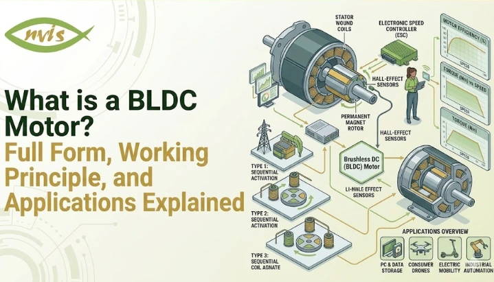
- What is a PMSM Motor? Full Form, Working Principle, and Applications Explained
- Working Principle of Electric Vehicle: A Complete Beginner’s Guide 2026
- Components of Electric Vehicle: A Beginner’s Complete Guide
What Is a PMSM Motor?
Before diving into the working principle, it helps to know what we are actually talking about.
A Permanent Magnet Synchronous Motor (PMSM) is a type of AC motor where the rotor uses permanent magnets instead of windings or electromagnets to create a magnetic field. stator, on other hand, is supplied with three-phase alternating current that produces a rotating magnetic field.
The key word here is “synchronous.” The rotor spins at exactly the same speed as the rotating magnetic field of the stator. There is no lag, no slip, two fields are always in lock-step.
Think of it like two gears perfectly meshed together. One gear (stator field) is driven by electricity. Another gear (rotor) follows it at the exact same rate.
This synchronous behavior, combined with permanent magnets on the rotor, gives PMSM its signature advantages: high efficiency, compact size, precise control, and minimal energy loss.
Construction of a PMSM Motor: What Is Inside?
To understand the working principle of a PMSM motor, you first need to know what it is made of. There are three core parts.
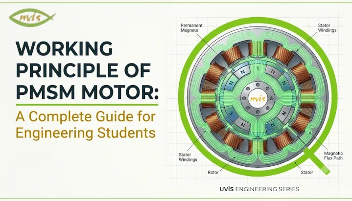
Stator
A stator is the outer stationary part of a motor. It contains three-phase copper windings distributed in slots around a laminated silicon steel core. When three-phase AC supply is connected to these windings, they produce a rotating magnetic field (RMF) that sweeps continuously around the stator’s inner circumference.
This rotating magnetic field is the “driving force” of PMSM. Its speed depends on supply frequency and number of poles in the motor.
Rotor
The rotor is the inner rotating part. Unlike a conventional synchronous motor that needs DC excitation through slip rings, PMSM rotor carries high-strength permanent magnets typically made from Neodymium-Iron-Boron (NdFeB) or Samarium-Cobalt (SmCo). These are rare-earth magnets known for their exceptional magnetic strength and thermal stability.
magnets create a constant, steady magnetic field in the rotor. This is what makes PMSM fundamentally different; no external excitation is needed to maintain the rotor’s magnetic field.
Based on how magnets are mounted, PMSMs are classified into two types: Surface-Mounted PMSM (SPMSM), where magnets are fixed on the outer surface of the rotor, and Interior PMSM (IPMSM), where magnets are embedded inside the rotor core. The IPMSM variant offers additional reluctance torque and is widely used in EV traction applications.
Air Gap
Between the stator and rotor is a small air gap typically just fractions of a millimeter. Magnetic flux passes through this air gap to create interaction between stator and rotor fields. Keeping this gap uniform and tight is crucial for efficiency and performance.
What Is the Working Principle of PMSM Motor?
Now comes the most important part in understanding exactly how a PMSM motor generates motion.
Step 1 Creating Rotating Magnetic Field
When three-phase alternating current is supplied to stator windings, it creates a magnetic field that rotates continuously. This happens because three phases (R, Y, B) are offset from each other by 120 degrees in time, so their combined effect produces a field that sweeps smoothly around stator circumference.
The speed of this rotating magnetic field is called synchronous speed (Ns). It is defined by formula:
Ns = 120f / P
Where f is supply frequency (in Hz) and P is number of poles.
For example, at 50 Hz with 4 poles, Ns = 120 x 50 / 4 = 1500 RPM.
Step 2 Magnetic Field Interaction and Torque Generation
permanent magnets on the rotor create a constant magnetic field. When the stator’s rotating magnetic field sweeps past the rotor, it interacts with the rotor’s permanent magnetic field.
According to electromagnetic principles, when two magnetic fields interact with an angular offset between them, a torque is produced. This torque tries to pull the rotor’s magnetic axis into alignment with the stator’s rotating field.
A good analogy is to imagine a compass needle placed inside a rotating external magnetic field. needle continuously chases external fields, trying to align with it. The rotor in a PMSM does exactly the same, but it “catches up” and locks on, spinning in synchronism.
Torque is theoretically maximum at a 90° torque angle, but in practical PMSM drives the angle is kept lower to ensure stability and efficient control. This is why precise control of this angle is critical in advanced PMSM drives.
Step 3 Synchronous Speed Operation and Zero Slip
Once the rotor locks onto a rotating magnetic field, it runs at exactly synchronous speed. There is zero slip between rotor and stator field.
This is a key differentiator from induction motors, where the rotor always runs slightly slower than the stator field (slip is necessary for induction to occur). In a PMSM, since the rotor magnetic field is independently created by permanent magnets, no induction is needed and slip is zero.
This zero-slip property translates directly into stable speed control, better efficiency, and more predictable torque behavior which is why PMSM motors are preferred in servo drives and EV applications.
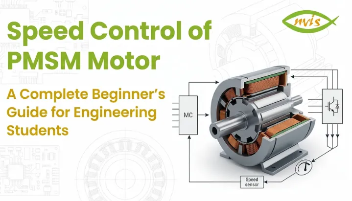
Step 4 Electronic Commutation via Inverter
Unlike a brushless DC (BLDC) motor that uses a trapezoidal back-EMF, a PMSM produces a sinusoidal back-EMF. This means PMSM motors require a sinusoidal current supply, precisely timed and controlled by an inverter (typically a three-phase PWM inverter).
The inverter adjusts frequency, magnitude, and phase of supply current to control speed and torque of the motor. This is done based on continuous feedback from a rotor position sensor (like an encoder or resolver), which tells the controller exactly where the rotor’s magnetic axis is at any instant.
This is why PMSM is always paired with an advanced motor controller; it cannot simply be plugged into a direct AC supply way an induction motor can.
PMSM Motor Working Principle: Role of Field-Oriented Control (FOC)
Once you understand the basic working principle of the PMSM motor, the natural next step is understanding how it is controlled in real applications.
The dominant control strategy for PMSMs is called Field-Oriented Control (FOC), also known as vector control.
Here is the core idea: in a PMSM, total stator current can be mathematically split into two components. First is d-axis current (Id), which controls magnetic flux. The second is q-axis current (Iq), which controls torque production.
By controlling Id and Iq independently similar to how you separately control voltage and current in a DC motor you get extremely fast and precise control over both speed and torque. This is what enables PMSM motors to accelerate and decelerate with exceptional smoothness, making them ideal for robotics, servo systems, and EV drivetrains.
d-q transformation (Park’s transformation) is a mathematical tool that converts three-phase rotating currents into these two simplified control components. It is a key topic in power electronics and motor drives courses, and understanding it gives you a real advantage in industries building smart motor systems
PMSM vs Induction Motor: Key Differences
A common question engineering students ask is why use a PMSM when induction motors are simpler and cheaper?
The answer lies in performance demands. Here is a quick comparison:
Parameter | PMSM Motor | Induction Motor |
Rotor Construction | Permanent magnets | Copper/aluminium cage windings |
Rotor Excitation | Not required | Required (induced) |
Slip | Zero (synchronous) | Always present (2-8%) |
Efficiency | Higher (often above 92-95%) | Slightly lower |
Power Density | High compact and lightweight | Lower for same output |
Speed Control | Precise, wide range | Good but less precise |
Cost | Higher initial cost | Lower initial cost |
Maintenance | Very low (no brushes or slip rings) | Low, but slip rings needed in wound rotor types |
Best Applications | EVs, servo drives, robotics | Industrial pumps, fans, general industry |
For applications where energy efficiency, compact size, and precise speed control matter more than upfront cost, PMSM is a better choice. This is exactly why electric vehicles, aerospace actuators, and CNC machines use PMSMs.
Advantages of PMSM Motors
Understanding why PMSM motors are so widely adopted helps you appreciate engineering decisions behind modern systems.
The most significant advantage is high efficiency. Since no current is needed to excite the rotor (magnets do that job on their own), rotor copper losses are eliminated. PMSM motors generally achieve higher efficiency than comparable induction motors because rotor copper losses are eliminated. Under comparable operating conditions, a meaningful difference at industrial scale.
A compact form factor is equally valuable. High-strength rare-earth magnets create intense magnetic flux in a small volume, allowing PMSM motors to deliver high torque and power from a much smaller and lighter frame than conventional motors. This is critical in EVs, where every kilogram matters for range.
PMSM motors can generate rated torque at zero speed when controlled by an appropriate inverter and motor drive, which makes them ideal for traction applications where high starting torque is required without need for additional starting circuits.
absence of brushes, commutators, and slip rings results in significantly lower maintenance requirements and longer operational life, an important consideration for industrial deployments running 24/7.
Finally, sinusoidal current supply results in smooth, ripple-free torque production, which reduces vibration and acoustic noise particularly valued in robotics and medical equipment.
Applications of PMSM Motors in India and Globally
The PMSM motor is no longer limited to specialty applications. It is now found across sectors, and its presence in India is growing rapidly.
Electric Vehicles
The single biggest driver of PMSM adoption worldwide is the EV industry India’s EV market has experienced rapid growth in recent years, driving increasing demand for high-efficiency traction motors such as PMSMs., with two-wheelers and three-wheelers commanding over 93% of that volume. Indian motor and powertrain manufacturers are actively developing PMSM-based solutions for electric two-wheelers, three-wheelers, commercial vehicles, and industrial applications and other Indian powertrain manufacturers are actively producing PMSM motors for electric two-wheelers, three-wheelers, e-tractors, and commercial vehicles with power outputs ranging from 400 W to over 150 kW.
Globally, the EV traction motor market was valued at USD 11.3 billion in 2024 and is projected to grow at a CAGR of over 33% through 2035. PMSMs and BLDC motors continue to gain market share over induction motors in EV drivetrains because of their efficiency advantage.
Industrial Automation and Servo Drives
Precision manufacturing, CNC machining centers, conveyor systems, and robotic arms rely on PMSM-based servo drives for their ability to execute fast, accurate movements. combination of zero slip and FOC control makes PMSM motors ideal for applications requiring rapid acceleration, deceleration, and position holding.
HVAC and Compressors
Variable-speed compressors in air conditioning systems including inverter AC units common across Indian households use PMSM technology to vary compressor speed with demand, reducing energy consumption significantly compared to fixed-speed alternatives.
Renewable Energy Systems
Wind turbine generators increasingly use PMSM-based direct-drive configurations that eliminate gearboxes, reducing mechanical complexity and maintenance requirements. This is an area of growing interest in India’s renewable energy expansion.
Aerospace and Defense
High-performance actuators, flight control systems, and electric propulsion for drones and UAVs use PMSM motors for their combination of high power density and precise controllability.
Career Opportunities for Engineering Students in PMSM and Motor Drives
If you are an electrical, electronics, or mechanical engineering student in India, understanding the working principle of PMSM motor opens up career pathways in some of the fastest-growing sectors.
Motor drive design and power electronics are in high demand across EV startups, established automotive companies like Tata Motors and Mahindra, and global Tier-1 suppliers setting up India operations. Roles in embedded control systems for motor controllers require knowledge of FOC algorithms, d-q modeling, and inverter design, all topics built on understanding PMSM fundamentals.
Research and development roles at institutions like IIT (Indian Institutes of Technology), NIT, and ISRO also engage with advanced motor technologies for aerospace and clean energy applications. Publications in motor control, magnet design, and EV drivetrains are active areas of academic research.
At industry level, core companies like BHEL, Siemens India, ABB India, and Bosch India regularly hire engineers with motor drives expertise for product development and application engineering positions. With India’s push toward domestic EV manufacturing under FAME II and PLI schemes, demand for motor systems engineers is expected to grow consistently through the rest of the decade.
Understanding PMSM theory is also foundational for pursuing advanced certifications in power electronics (like IEEE certifications), MATLAB/Simulink-based motor modeling, and embedded motor control using platforms like STM32, NXP, or TI microcontrollers.
Conclusion
The working principle of the PMSM motor comes down to a beautifully coordinated electromagnetic interaction: a rotating magnetic field from a stator that permanent-magnet rotor locks onto and follows at exactly synchronous speed. No slip, no rotor windings, no brushes. Just precise, efficient, low-maintenance rotation driven by interaction of two magnetic fields.
What makes PMSM so relevant today is not just its physics but its positioning. As India accelerates EV adoption, scales up industrial automation, and builds out renewable energy infrastructure, PMSM motors are at the center of that transition. Understanding this technology gives engineering students a direct line into some of the most exciting and rapidly expanding career domains in electrical engineering.
Start with basics: rotating magnetic field, synchronous speed, torque angle. Then move into control FOC, d-q modeling, inverter design. Each layer you add builds practical knowledge that has genuine market value in India’s evolving engineering landscape.
FAQs
The PMSM motor works by creating a rotating magnetic field in the stator using a three-phase AC supply. permanent magnets on the rotor lock onto this rotating field and spin at the same synchronous speed. The working principle of the PMSM motor is based on electromagnetic torque produced when the stator field and rotor field interact at an angular offset.
The main difference is in the rotor. An induction motor has a wound or cage rotor that relies on electromagnetic induction to produce torque, resulting in slip between rotor speed and synchronous speed. A PMSM rotor carries permanent magnets that create a constant field independently, eliminating slip and improving efficiency. PMSMs also require an inverter and position feedback for operation, unlike basic induction motors.
A PMSM requires a sinusoidal current precisely timed with rotor position to produce smooth, efficient torque. A standard AC supply does not provide this level of control. A three-phase inverter, guided by rotor position feedback from a sensor, generates correctly shaped and phased current to drive the motor. This is fundamentally different from a simple induction motor that can run directly from the grid.
PMSMs are classified into two main types based on magnet placement. Surface-Mounted PMSM (SPMSM) has magnets fixed on the outer surface of the rotor and offers simpler construction and control. Interior PMSM (IPMSM) has magnets embedded inside the rotor core, which adds reluctance torque and improves performance at high speeds. IPMSM is widely used in electric vehicle traction applications for this reason.
. What magnet material is used in PMSM motors and why?
Field-Oriented Control (FOC), also called vector control, is an advanced control technique used to drive PMSM motors. It decomposes stator current into two independent components flux-producing current (Id) and torque-producing current (Iq) enabling separate, precise control of each. This approach gives PMSM motor fast dynamic response and smooth torque control needed in EVs, robotics, and servo systems. FOC is a critical topic in power electronics and motor drives for any engineering student targeting careers in these industries.