





• Nvis Technology
  • Nvis Technology
  • Nvis Technology
  • Nvis Technology
  • Nvis Technology
  • Nvis Technology
Nvis Technology

Head Office

141-A, Electronic complex, Pardesipura,Indore - 452010 India

Phone: +91 73899 00887 , +91 98932 70303

Email:info@nvistech.com

Request a Quote

Looking for a quality and affordable builder for your next project?


    Nvis Technology

    Toll Free

    +91 73899 00887

    We are happy to meet you during our working hours. Please make an appointment.

    • Monday-Saturday: 9:00 AM - 5:30 PM (IST)
    • Sunday: Closed

    ARM Cortex M Microcontrollers Explained: Architecture for Embedded Engineering Students

    TL;DR

    1. This blog is for ECE, EEE, and CSE students, freshers, and GATE/SSC JE/RRB JE aspirants who want to understand what an ARM Cortex M microcontroller actually is and how its architecture works, from first principles.
    2. This blog explains what Arm means in the context of microcontroller design and examines the Cortex-M architecture step by step, helping beginners understand the role of each major component rather than simply memorizing terminology.
    3. This post builds concepts step by step: what ARM in a microcontroller means, how core, registers, memory, and NVIC fit together, and how M0, M3, M4, and M7 variants differ in real numbers.
    4. A worked numerical example on interrupt latency shows exactly how to calculate real time response time, the kind of calculation GATE and SSC JE papers expect you to solve.
    5. The post closes with India specific employer and salary context, exam relevance, and a comparison table so you leave with both conceptual clarity and exam ready facts.
    ARM Cortex-M processors are used in many embedded products, including automotive control systems, fitness trackers, and other connected devices. Nowadays, it has become necessary for all embedded systems related jobs in India to understand the architecture of ARM Cortex M microcontroller, which is relevant to microcontroller, processor, interrupt, and computer-architecture concepts tested in engineering and technical examinations. This blog provides an explanation of the meaning of ARM in the context of microcontroller design, examines the Cortex M architecture, one by one, and illustrates the differences between the M0, M3, M4 and M7 cores with real specifications, not with marketing-speak. By the end of this article, you should be able to understand the major sections of a Cortex-M microcontroller datasheet and interpret common architectural terms.

    Also read,

    What Is ARM in Microcontroller?

    Arm develops processor architectures and processor IP, including the Cortex family of CPU cores. Cortex-M is its microcontroller-oriented processor profile. Arm is not a microcontroller manufacturer. Instead, it licenses its architectures and processor IP to semiconductor companies, which integrate Arm-based CPU cores with memory and peripherals to create complete microcontrollers and SoCs.These companies combine Arm processor cores with flash, RAM, timers, GPIO, ADCs, communication interfaces, and other hardware to create complete microcontrollers and SoCs.ARM processors are based on the RISC (Reduced Instruction Set Computing) design philosophy. RISC is made up of a rather limited number of simple instructions that are executed efficiently and quickly. RISC processors usually have fewer and simpler instructions than the traditional CISC processors with their longer, more complex instructions, and the execution is more efficient and processor design is more streamlined.This architecture can be seen in microcontrollers such as the ARM Cortex-M family of processors, including the Cortex-M0, Cortex-M3, Cortex-M4, Cortex-M7 and new Cortex M processors. For example, a Cortex-M4-based microcontroller can provide substantially higher computational performance than many older 8-bit MCUs because it combines a 32-bit architecture with a more capable instruction set, higher processing throughput, and, in many implementations, higher clock frequencies.So, if someone mentions the ARM in the context of a microcontroller, it is usually referring to the architecture or core, and the entire microcontroller is manufactured by a chip maker who adds memories, peripherals, and other hardware to the ARM core.

    Why Cortex M Family Exists ?

    Before Cortex-M became widely adopted, embedded systems commonly ranged from low-cost 8-bit MCUs to more capable 32-bit processors and microcontrollers. Before Cortex-M became widely adopted, embedded systems ranged from low-cost 8-bit and 16-bit microcontrollers to more capable 32-bit processors and microcontrollers. Lower-end MCUs were suitable for simple control tasks, while more capable 32-bit devices were used when applications required greater processing performance, memory, connectivity, or operating-system support. But in between, Arm targeted applications that needed more computational capability than traditional low-end MCUs could comfortably provide, while still requiring low cost and low power consumption.ARM’s response was the Cortex M series. M is for Microcontroller profile, one of three ARM processor profiles, the other two are Cortex A (smartphones and laptops) and Cortex R (real time systems such as automotive braking controllers). Cost-sensitive, predictable and interrupt-driven embedded systems, devices that require predictable and timely responses to real-world events, were the target of Cortex M, which was designed for these applications.This one design choice is the cause of nearly all others in architecture.Many Cortex-M systems combine efficient interrupt handling with low-power features to support responsive operation in resource-constrained embedded applications.

    Breaking Down ARM Cortex M Microcontroller Architecture

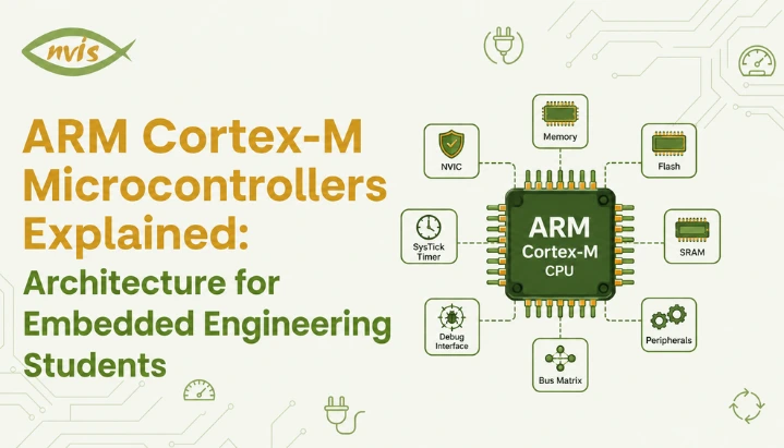
    An ARM Cortex M microcontroller is not one single block. It is a small collection of cooperating units, each with a clear job. Picture a compact factory floor: a supervisor giving instructions, workers carrying out tasks, a filing cabinet of short term notes, a warehouse of long term records, and an alarm system that interrupts everyone the moment something urgent happens. That is roughly how pieces of a Cortex M microcontroller work together.

    Processor Core: Supervisor

    processor core is the part that actually executes instructions. It contains an Arithmetic Logic Unit, which performs calculations, along with control logic that decides what happens next. Every instruction your embedded C code compiles down to eventually passes through this core.

    Registers: Filing Cabinet on Desk

    Registers are small, fast storage locations built into the processor and used to hold values that the CPU needs frequently. A Cortex-M core provides general-purpose registers R0 to R12. The SP (Stack Pointer) points to the current stack location, the LR (Link Register) is commonly used to hold a return address, and the PC (Program Counter) holds the address of the instruction being executed or fetched, depending on the processor state. There is also a Program Status Register (PSR) that stores flags like zero, carry, overflow, and negative, which the processor checks when making decisions such as branching on a comparison.

    Memory: Flash for Long Term Storage, SRAM for Working Space

    Flash memory is where your compiled firmware lives permanently. It does not lose data when power is removed, which is why your microcontroller boots up running the same program every time. SRAM, on other hand, is fast but volatile working memory used for variables, stack, and runtime data while a program executes. If Flash is a warehouse where finished records are archived, SRAM is a desk where you actively work on today’s task.

    Bus Architecture: Delivery Routes

    Cortex-M implementations use bus interfaces that can provide separate instruction and data paths, with the exact bus structure depending on the Cortex-M core and the microcontroller implementation. This separation can allow instruction fetching and data access to proceed concurrently. However, the actual performance depends on the Cortex-M core, bus structure, memory system, and microcontroller implementation.

    NVIC: How Cortex M Handles Interrupts So Well

    When it comes to a characteristic of Cortex M architecture, there is one thing that stands out: Nested Vectored Interrupt Controller (NVIC). The interrupt is just a signal to the processor to stop doing what it’s doing and come to attention immediately, and process something else, like a button click, a sensor reading above or below a threshold, an incoming UART byte, etc.Now suppose you were in the kitchen and the telephone rang. The entire recipe is not completed at once. You identify where you paused, respond and then cook from the same point. The Cortex-M exception-handling mechanism automates much of this behavior in hardware. When an interrupt or exception is taken, the processor automatically saves a defined exception stack frame, transfers execution to the corresponding handler, and restores the interrupted context when exception return occurs. The NVIC specifically manages interrupt prioritization, pending status, and interrupt delivery. This removes the need for software to manually save and restore the standard exception-frame registers. No line of manual register saving logic in your code.When an interrupt fires, The Cortex-M processor automatically saves the standard exception stack frame, enters the Interrupt Service Routine (ISR), and restores the interrupted context when the ISR returns through the exception-return mechanism.NVIC supports programmable interrupt priorities, allowing a higher-priority interrupt to preempt a lower-priority handler when the architecture and current interrupt state permit it. This is called nesting and the “Nested” in NVIC is derived from that. Tail chaining is another feature of Cortex M processors, the idea is Tail-chaining allows a pending exception to be serviced directly after another ISR without performing a full exception return and then a separate exception entry sequence, reducing interrupt-handling overhead.

    Worked Numerical Example: Calculating Interrupt Response Time

    This is a useful example of converting processor clock cycles into real-time latency, a calculation that can help with microcontroller and digital-system timing problems so it is worth working through carefully.Problem: A Cortex M3 based microcontroller runs at a clock speed of 72 MHz. For this simplified example, assume an interrupt latency of 12 clock cycles from interrupt recognition to execution of the first ISR instruction.  If ISR itself takes 150 clock cycles to complete, calculate total time in microseconds from interrupt assertion to ISR completion.Step 1: Find the time period of one clock cycle.Clock speed = 72 MHz = 72 × 10⁶ cycles per secondTime per cycle = 1 / (72 × 10⁶) seconds = 0.01389 microseconds (approximately)Step 2: Find total number of clock cycles involved.Total cycles = interrupt latency + ISR execution time = 12 + 150 = 162 cyclesStep 3: Multiply total cycles by time per cycle.Total time = 162 × 0.01389 microseconds = 2.25 microseconds (approximately)So the entire interrupt handling process, from interrupt signal being raised to ISR finishing its job, takes just about 2.25 microseconds on this Cortex M3 system. An older 8-bit architecture may have a different interrupt-entry sequence and instruction timing, so its latency can be higher or lower depending on the specific MCU. The key point is that Cortex-M provides a standardized and efficient hardware mechanism for exception entry and interrupt handling because the processor may need to finish a multi cycle instruction before it can even begin saving context. This kind of predictable and efficient interrupt handling is one reason Cortex-M devices are widely used in real-time applications such as motor control and sensor processing.

    Cortex M0, M3, M4, and M7: How Family Actually Differs

    Every Cortex M core shares the same basic philosophy, but they are tuned for different jobs, the same way a scooter, a hatchback, and a highway coach are all vehicles built for very different journeys. Here is how most widely used variants actually compare, using real specifications rather than vague labels like “better” or “faster.”
    FeatureCortex M0/M0+Cortex M3Cortex M4Cortex M7
    ArchitectureARMv6 MARMv7 MARMv7 MARMv7 M
    Pipeline stages2336 (superscalar)
    DSP instructionsNoNoYesYes
    Hardware FPUNoNoOptional (single precision)Optional (single and double precision)
    Hardware divideNoYesYesYes
    Typical use caseSimple sensors, basic controlGeneral embedded controlMotor control, audio, signal processingHigh speed real time processing, advanced HMI
    Example MCUSTM32F0 seriesSTM32F1 seriesSTM32F4 seriesSTM32H7 series
    In practice, it’s simple to see when you look at it like this. Cortex M0 and M0+ are designed to be used in the most power and cost sensitive applications, including simple sensors and basic consumer electronics, where the extent of battery life is more critical than raw performance. Cortex-M processors integrate the NVIC into their interrupt architecture, with capabilities varying across generations. The Cortex-M family provides a 32-bit processing platform suitable for applications ranging from simple control tasks to more demanding embedded workloads. Cortex-M4 adds DSP-oriented instructions, while an FPU is available in FPU-equipped implementations, explaining its predominance in applications such as motor control algorithms or audio processing that rely heavily on mathematical operations. The performance of Cortex-M7 uses a 6-stage dual-issue superscalar pipeline, allowing up to two instructions to be issued per cycle under suitable conditions, thus providing headroom for high demanding applications such as high resolution display control or high end signal processing, where the M4 may have begun to be limited.

    ARM Cortex M in Indian Embedded Industry

    ARM Cortex M is no ordinary study content for engineering students in India. It’s a family of chips that are actually installed in products created by companies you can expect to interview with. The STM32 series, one of the most popular and utilized Cortex M families in Indian engineering colleges, drives projects ranging from student project boards to industrial controllers.Embedded engineers are recruited in the government tied and defence organizations such as ISRO, DRDO, BEL and HAL for working with microcontrollers based on ARM for subsystems in satellite, radar and communication equipment. The initial roles for freshers in embedded systems are around 3.5 to 6 LPA in an organization such as Bosch, Continental, L&T Technology Services, Tata Elxsi, Sasken, Honeywell and NXP and with 2-3 years experience in a particular field, the pay scale can be from 8 to 14 LPA. Generally, Engineers with fresher experience are hired for 3.5 to 6 LPA in hubs such as Bangalore and increased to 7 to 12 LPA after two years, and for jobs in the automotive and RTOS specialization, they are paid 12 to 20 LPA.With India’s expanding electronics and semiconductor ecosystem, embedded and firmware skills are receiving increasing attention. Engineers who understand microcontroller architecture at a deeper level can have an advantage over candidates whose experience is limited to using high-level development environments such as the Arduino IDE. Embedded positions in the automotive industry, such as those for engine management systems, battery management systems, and in general when dealing with embedded systems, can pay between 7 and 35 LPA, depending on experience, and Automotive embedded roles can offer strong compensation, particularly for engineers with experience in areas such as AUTOSAR, functional safety, embedded C/C++, automotive protocols, and RTOS-based development.

    GATE, SSC JE, and RRB JE Exam Relevance

    Microprocessor and digital-system concepts are relevant to GATE ECE preparation, but the exact syllabus classification and question patterns should be checked against the current official syllabus, and questions on interrupt handling, register architecture, and instruction execution timing are common numerical problem types. Microprocessor, microcontroller, and digital-system concepts have appeared in GATE over the years, but their frequency and marks vary from paper to paper, and Questions may use concepts that are also relevant to modern Cortex-M-based systems, even when the specific processor architecture is not named.For SSC JE and RRB JE electronics and electrical papers, microcontroller architecture questions tend to focus on conceptual understanding: what registers do, how interrupts are prioritised, and practical difference between RISC and CISC design. A worked example earlier in this post, calculating total interrupt response time from clock speed and cycle counts, is a template you can reuse directly, since these exams frequently rephrase the same underlying calculation with different clock speeds and cycle counts.A practical exam strategy is to master register sets (R0 to R12, SP, LR, PC, PSR) cold, understand NVIC’s priority and nesting behaviour conceptually, and practice cycle to time conversions until they become automatic. These three areas cover several important microcontroller-architecture concepts that are useful for GATE, SSC JE, and RRB JE preparation.

    Building a Career Around ARM Cortex M Skills

    If you are early in your engineering degree, the most useful thing you can do is get hands on with an actual Cortex M development board rather than only reading about architecture. STM32 Nucleo boards and similar Cortex M4 based development kits are inexpensive, well documented, and directly relevant to what Indian embedded employers expect from freshers.ECE engineers in embedded systems and VLSI roles typically reach 10 to 18 LPA at mid level, with three to five years of experience, and embedded specific specialisation tends to compound this further. Semiconductor firmware roles working close to silicon level, including Cortex M based firmware, are among higher paying segments within embedded systems, with mid to senior engineers at semiconductor companies earning 15 to 35 LPA.A skill progression that consistently works for Indian embedded freshers looks like this: start with Embedded C fundamentals, move to bare metal Cortex M programming using register level code before relying entirely on vendor libraries, then layer in an RTOS like FreeRTOS once fundamentals are solid. Employers consistently value candidates who understand what is happening underneath the abstraction layer, not just candidates who can call a library function.

    Conclusion

    ARM Cortex M microcontrollers earned their dominant position in embedded systems by solving a real problem:delivering 32-bit processing capabilities while targeting the cost and power constraints of many embedded applications with an interrupt handling system fast enough for real time applications. Understanding this architecture means going beyond memorising terms like NVIC or PSR and instead grasping why each piece exists and how they work together, from the register set that provides the CPU with fast access to frequently used values, to bus architecture that lets instruction fetch and data access happen in parallel.For Indian engineering students, this knowledge pays off twice. It builds conceptual foundations that GATE, SSC JE, and RRB JE numerical questions test directly, and it builds practical skill sets that embedded employers, from STMicroelectronics and Bosch to ISRO and DRDO, actually hire for. Start with a Cortex M4 development board, work through register level programming before jumping to abstraction libraries, and practice interrupt timing calculations until they feel automatic. That combination is what turns textbook knowledge into an actual embedded systems career.

    FAQs

    Arm is a company that develops processor architectures and CPU designs and licenses them to semiconductor companies, who then build complete microcontrollers around that design by adding memory, timers, and peripherals. When people ask what ARM is in microcontroller terms, they are really asking about processor core design inside the chip, not the finished product itself.

    Cortex-M is Arm’s microcontroller-oriented processor profile, while Arm also develops Cortex-A and Cortex-R processor families for other types of systems. ARM also offers Cortex A profile for application processors used in smartphones and Cortex R profile for real time systems, so Cortex M specifically refers to the microcontroller focused branch of ARM’s designs.

    An ARM M4 microcontroller adds DSP instructions and an optional Floating Point Unit that a Cortex M3 does not have, which matters for signal processing and motor control projects. For pure learning purposes, either core teaches the same fundamental register and interrupt concepts, so beginners can start with whichever development board is more easily available.

    Cortex M processors balance computing power, low power consumption, and cost in a way few alternatives match, which is exactly what battery powered IoT sensors need. scalability across M0 to M7 variants also means a single ecosystem of tools and knowledge covers products ranging from simple sensors to advanced edge devices.

    GATE ECE includes microprocessor, digital-system, and computer-architecture concepts. The exact processor families and question emphasis vary across papers and years, but interrupt handling, register architecture, and cycle-time calculations are useful concepts to understand, register architecture, and cycle time calculations, all core Cortex M topics, are directly testable regardless of which specific processor family a question references. Practicing clock cycle to time conversion shown in this post prepares you for this question type regardless of exact architecture named.

    Embedded C is the dominant language for Cortex M firmware development in industry, often supplemented with a small amount of ARM assembly for startup code or highly time critical routines. C++ is increasingly used as well, particularly in larger projects that use an RTOS like FreeRTOS or Zephyr.

    STMicroelectronics, Bosch, Continental, L&T Technology Services, Tata Elxsi, Sasken, and NXP are among private companies hiring for Cortex M based embedded development, alongside PSUs and defence organisations like ISRO, DRDO, BEL, and HAL. Compensation varies by employer, location, role, and experience, with specialized skills such as RTOS and automotive protocols potentially improving a candidate’s opportunities.
    Tags: ARM in Microcontrolle

    Motor Control Using Microcontroller: PWM, H Bridge and Interfacing Basics

    TL;DR

    1. This blog is for ECE, EEE, and mechatronics students, freshers, and GATE or SSC JE aspirants who want to understand motor control using microcontroller techniques from ground up.
    2. Many motor-control applications need control over two key parameters: speed and direction. A microcontroller cannot supply current a motor needs, so it relies on PWM signals and an H bridge circuit to do its job safely.
    3. PWM (Pulse Width Modulation) controls motor speed by rapidly switching power on and off, while H bridge controls direction by reversing current flow through the motor.
    4. The term “motor control” is also used in industrial electrical systems, where a Motor Control Center (MCC) panel controls and protects multiple motors. This is different from microcontroller-based motor control and is explained later for clarity.
    5. Understanding this topic well can open doors to embedded systems, robotics, EV, and industrial automation roles at companies and PSUs like ISRO, DRDO, BHEL, and Tata Motors, along with strong marks in GATE and SSC JE papers.

    Motor control is an important part of many robotics, automation, embedded, and mechatronics projects. A microcontroller determines when to start a motor, how fast to spin it and in which direction, but it cannot do this on its own. It requires two concepts: Pulse Width Modulation (PWM) to control speed, and an H bridge circuit to control direction. This blog explains both concepts in plain english, goes over a worked numerical example and even clears up a common point of confusion between motor control with a microcontroller and a Motor Control Center (MCC) panel in industrial plants, both of which are frequently mentioned in electrical engineering courses and papers.

    Also read,

    Why Can’t a Microcontroller Drive a Motor Directly?

    Imagine a microcontroller pin as a small control switch. It can send a signal to tell another circuit when to turn on or off, but it cannot supply the large amount of current needed to drive a motor directly. A motor driver acts as the power-handling stage between the microcontroller and the motor. The microcontroller sends a 3.3V or 5V control signal to the driver, while the driver handles the higher current required by the motor.

    A DC motor can draw a much higher current during startup than during normal operation because the motor initially has little or no back EMF. This startup or stall current can be several times the motor’s normal running current. When a motor is connected directly to a pin on a microcontroller, it is not being powered. You’re cooking your microcontroller.

    That is why a microcontroller-based motor-control system normally uses a motor-driver or power-switching stage between the microcontroller and the motor. Depending on the motor and required control, this stage may use an H bridge, half-bridge, MOSFETs, or another suitable driver circuit. PWM may then be used to control speed.

    What Is PWM and How Does It Control Motor Speed?

    Imagine you are filling a bucket using a tap that only has two positions: fully open or fully closed. You cannot set it to a gentle trickle. But if you open and close that tap very quickly, say open for 7 seconds and closed for 3 seconds, every 10 seconds, the bucket still fills up, just at 70 percent of tap’s maximum flow rate. That is the entire idea behind Pulse Width Modulation.

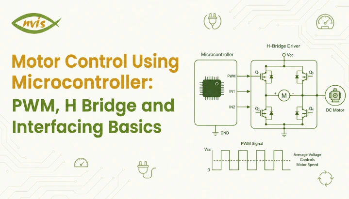
    PWM works by switching a digital output on and off at a fixed frequency, and the proportion of time it stays on during each cycle is called duty cycle. The motor does experience the individual switching pulses, but its electrical and mechanical dynamics prevent its current, torque, and speed from following each switching transition instantaneously. Because the motor’s electrical and mechanical characteristics smooth the switching waveform, PWM produces an average effect on motor current and torque. For basic calculations, the average applied voltage is often approximated as

    Vavg​=Vs​D.

    relationship is refreshingly simple:

    Average Voltage = Supply Voltage × Duty Cycle

    So if a 12V motor is driven with a 60% PWM duty cycle, the **average terminal voltage over a PWM cycle** is approximately 7.2V under ideal switching conditions. However, the motor’s actual speed will not necessarily be exactly 60% of its full-speed value because speed also depends on load, motor characteristics, back EMF, winding resistance, and the driver circuit. Increase the duty cycle and the motor will generally speed up under the same load. Decrease it and the motor will generally slow down. PWM switching can be much more efficient than using a linear voltage-control method, although the motor, switching devices, wiring, and driver still have power losses.

    Worked Numerical Example on PWM Duty Cycle

    This is a useful practice problem because it combines duty cycle, switching frequency, and average-voltage calculations that are relevant to power-electronics fundamentals.

    Question: A DC motor is rated for 24 V. It is being driven by a PWM signal at a switching frequency of 1 kHz with a duty cycle of 65%. Calculate the average voltage applied to the motor and the corresponding on-time of each PWM pulse.

    Step 1: Calculate average voltage. Average Voltage = Supply Voltage × Duty Cycle Average Voltage = 24V × 0.65 Average Voltage = 15.6V

    Step 2: Calculate total time period of one PWM cycle. Time Period (T) = 1 / Frequency T = 1 / 1000 Hz T = 1 millisecond (1 ms)

    Step 3: Calculate on time using duty cycle. On Time = Duty Cycle × Time Period On Time = 0.65 × 1 ms On Time = 0.65 ms (or 650 microseconds)

    So in every 1 millisecond cycle, the motor receives a full 24V pulse for 0.65 ms and 0V for remaining 0.35 ms,giving an average terminal voltage of 15.6V over each PWM cycle under ideal switching conditions. This single formula, average voltage equals supply voltage multiplied by duty cycle, is worth memorizing cold for exams, since this type of duty-cycle and average-voltage calculation is useful for power-electronics fundamentals and exam preparation.

    What Is an H Bridge and Why Does Direction Control Need One?

    Speed is only half a story. Most real applications, robots that reverse, wipers that go back and forth, elevators that go up and down, also need motors to spin in both directions. This is where the H bridge comes in.

    Picture four gates arranged in the shape of letter H, with a motor sitting across the middle bar of that H. In the basic forward-drive state, current flows from the positive supply through one high-side switch, the motor, and one low-side switch to the negative supply. If one diagonal pair of switches is turned ON, current flows through the motor in one direction. Turning that pair OFF and activating the opposite diagonal pair reverses the current through the motor, causing it to rotate in the opposite direction. That is the whole trick. No moving parts, no manually swapping wires, just electronically choosing which diagonal path gets activated.

    In practice, these “gates” are transistors or MOSFETs, and they are usually packaged into a ready made driver IC so students and engineers do not need to build a switching circuit from scratch. The most common ones you will encounter in a lab are L293D, L298N, and more modern TB6612FNG.

    Depending on the driver IC, a microcontroller may provide two direction-control signals along with a PWM or enable signal. The direction inputs determine the motor’s current path, while PWM controls the effective power delivered to the motor. Some driver ICs also provide a separate enable input for disabling the output stage.

    One Critical Warning: Shoot Through Current

    The high-side and low-side switches on the same half-bridge must not be turned on simultaneously. Doing so can create a low-impedance path directly across the supply, producing a large shoot-through current that can damage the switching devices. Proper drivers often use interlocking or dead-time control to prevent this condition. This is why H-bridge designs must prevent both switches in the same half-bridge from being ON simultaneously. Many dedicated drivers provide interlocking and dead-time internally; in other designs, the controller or firmware may need to ensure appropriate timing when switching states.

    Comparing Popular Motor Driver ICs for Microcontroller Projects

    Driver ICMotor ChannelsMax Current per ChannelMax VoltageTypical Use Case
    L293D20.6A (1.2A peak)36VSmall hobby robots, college mini projects
    L298N22A46VMedium robots, small conveyor models
    TB6612FNG21.2A (3.2A peak)15VCompact robotics, drone ground stations
    BTS7960143A27VHigh torque robots, e bike prototypes, EV mini projects

    L293D and L298N are still widely encountered in educational projects, although newer MOSFET-based drivers are generally more efficient and produce less voltage drop due to their low cost and widespread availability across Indian electronics markets like Lamington Road in Mumbai and SP Road in Bangalore. For applications requiring substantially more current, such as higher-power robotic platforms or some small vehicle prototypes, a higher-current driver such as a BTS7960-based module or another appropriately rated motor controller may be considered.

    Microcontroller Motor Control vs Motor Control Center Panel: Don’t Confuse Two

    Here is a genuine point of confusion for many students: “motor control” appears in two very different contexts in electrical and electronics engineering, and interviewers love to test whether you know the difference.

    Microcontroller motor control, everything covered above using PWM and H bridges,is commonly used to control small and medium DC motors through an appropriate driver or power stage, with motor voltage and current determined by the motor and driver requirements. It is the domain of embedded systems, robotics, and mechatronics.

    A Motor Control Center (MCC) panel, sometimes just called a motor control panel, is an entirely different piece of industrial equipment. It is a large enclosed assembly, often the size of a cupboard or bigger, containing multiple motor starters, circuit breakers, contactors, and overload relays, all sharing a common power bus. An MCC panel distributes and controls power for multiple industrial motors, often three-phase motors. In India, many low-voltage industrial systems operate around 415V AC, although actual system voltages and configurations vary by application.

    AspectMicrocontroller Motor ControlMotor Control Center (MCC) Panel
    ScaleSingle small motorMultiple large industrial motors
    Typical Voltage5V to 24V DC415V AC, 3 phase
    Core TechniquePWM and H bridge switchingContactors, starters, overload relays
    Where You’ll Find ItRobotics, embedded projects, dronesFactories, water treatment plants, power stations
    Who Designs ItEmbedded systems or electronics engineerElectrical engineer, panel design engineer

    Both are legitimately called “motor control,” and both are worth understanding, since your career could head in either direction depending on whether you gravitate toward embedded systems or industrial electrical design.

    Interfacing Basics: Connecting It All Together

    A typical motor control using microcontroller setup follows a consistent wiring pattern regardless of which microcontroller or driver IC you choose.

    The motor should normally be powered through the driver’s motor-supply path rather than directly from a microcontroller GPIO or regulator output. The motor supply should be selected according to the motor and driver requirements. Sharing grounds between microcontroller and motor’s power supply is essential, since both circuits need a common reference point for their signals to make sense.

    The microcontroller’s PWM capable pin connects to the driver’s enable or PWM input pin. On an Arduino, this is typically a pin marked with a tilde symbol, like pin 9 or pin 10, since not every digital pin supports hardware PWM. On an STM32, this involves configuring a timer peripheral in PWM mode through the microcontroller’s timer registers.

    Two regular digital output pins from the microcontroller connect to driver’s direction control inputs, deciding clockwise or counter clockwise rotation.

    Bulk and ceramic bypass capacitors should be placed close to the motor driver according to the driver’s datasheet and the motor’s current transients. A bulk capacitor such as 47–470 µF may be appropriate in some small DC-motor circuits, but the exact value should be selected based on the supply, wiring, motor, and driver.

    Why This Topic Matters for GATE, SSC JE, and RRB JE Aspirants ?

    Motor-control concepts can overlap with several areas covered in competitive engineering exams, including power electronics, electrical machines, and control systems.

    In GATE Electrical Engineering, DC machines and motor-related speed-control concepts are relevant to the Electrical Machines portion of the syllabus, and PWM-based control can be used to frame numerical questions involving duty cycle, switching frequency, average voltage, and motor-control concepts.

    For GATE ECE and other engineering exams, related concepts such as digital timing, PWM, switching devices, and power-electronics fundamentals may be relevant depending on the syllabus and question, often as circuit identification or truth table questions asking which transistor pair should conduct for a given direction.

    For SSC JE and RRB JE preparation, these concepts can be useful when studying power electronics, electrical machines, switching devices, and motor-control fundamentals. The exact question types and topic coverage depend on the relevant syllabus and exam pattern, The exact coverage depends on the syllabus and paper pattern, but candidates may encounter both conceptual and numerical questions involving duty cycle, switching devices, and motor-control fundamentals.

    A practical tip for exam preparation: always draw an H bridge diagram from memory and label current flow for both directions before an exam. Students who can visualize current paths solve direction related questions far faster than those relying purely on memorized rules.

    Career Scope and Salary Guidance for Motor Control and Embedded Systems Roles

    Skills in motor control using microcontroller techniques translate directly into embedded systems, robotics, and increasingly EV powertrain roles, all of which are in strong demand across Indian industry right now.

    Freshers entering embedded systems roles typically start in the range of 3 to 8 LPA, with product based companies and semiconductor firms offering toward the higher end of that band compared to service based IT companies. With three to six years of experience, particularly with exposure to automotive or EV embedded systems, professionals commonly move into the 10 to 18 LPA range, and senior embedded architects at companies working on automotive or semiconductor products can cross 25 to 35 LPA.

    On government and PSU side, Organizations such as ISRO, DRDO, BEL, and BHEL recruit electrical and electronics engineers for a range of technical roles, some of which may involve control systems, power electronics, actuators, drives, or related technologies. Recruitment routes vary by organization and role; some positions use GATE scores, while others may follow organization-specific recruitment processes or examinations, making strong fundamentals in motor control, power electronics, electrical machines, and embedded systems useful for relevant technical roles and interviews.

    The growth of India’s EV sector, supported by government initiatives including PM E-DRIVE, has increased attention on electric-drive, power-electronics, battery, and embedded-control technologies. This dual understanding, small scale PWM and H bridge control alongside larger industrial motor control concepts, is increasingly what separates a strong embedded or EV engineering candidate from an average one.

    Conclusion

    Motor control using microcontroller systems boils down to two cooperating ideas. PWM handles speed by rapidly switching power to create an average voltage effect, and H bridge handles direction by rerouting current through one of two diagonal paths. Together, with a driver IC bridging the gap between your microcontroller’s weak signal and motor’s real power needs, these concepts form the backbone of everything from hobby robots to industrial drive systems. Keep distinction between this microcontroller level control and industrial Motor Control Center panels clear in your mind, since both terms will follow you through your academic and professional journey. Practice duty cycle and average voltage numerical shown above until it feels automatic, since it is one of most exam friendly calculations in this entire subject area. Start with a simple DC motor project using a suitable motor-driver module. Older drivers such as the L293D and L298N are common in educational projects, while newer MOSFET-based drivers may offer better efficiency and lower voltage losses.

    FAQs

    PWM controls motor speed by rapidly switching supply voltage on and off to create an average effective voltage, while an H bridge controls direction of rotation by reversing the current path through the motor. They work together, not as alternatives, in most motor control using microcontroller systems.

    Yes. Motor speed can be controlled using methods such as varying the applied voltage, using a linear regulator in suitable low-power applications, or using other motor-drive techniques. However, PWM is generally preferred for DC motor speed control because switching control can achieve high efficiency.

    A microcontroller pin can only supply a few milliamps of current, while even a small DC motor demands hundreds of milliamps or more, especially during startup. An H-bridge driver acts as a power-switching stage that allows the microcontroller to control a motor using a separate power supply while also reversing the motor’s current direction.

    No, these are different concepts despite sharing similar terminology. An MCC is an industrial assembly used to distribute power and provide switching, protection, and control for multiple motors, commonly three-phase motors using starters, contactors, and circuit breakers, typically at 415V AC, whereas H-bridge motor control at the microcontroller level is commonly used with small DC motors, with the motor voltage determined by the selected driver and power supply.

    L293D and L298N remain most beginner friendly choices due to low cost, wide availability across Indian electronics markets, and abundant tutorial support. Consider a higher-current driver when the motor’s rated and startup/stall current exceed the safe operating limits of the chosen driver.

    Yes. DC-motor speed-control concepts are relevant to electrical-engineering exam preparation, while PWM and switching concepts are relevant to power electronics and related electronics topics. The exact coverage depends on the syllabus and exam.

    Tags: Motor Control Using Microcontroller

    Request a Callback

    Please enable JavaScript in your browser to complete this form.

    No spam. Just a quick call.

    =