







TL;DR
- This blog is for engineering students, freshers, and anyone preparing for GATE, SSC JE, RRB JE, or discom JE exams who wants to actually understand Sumpner’s test, not just memorize it.
- Sumpner’s test (also called back to back test) lets you find a transformer’s iron loss and copper loss together, at full load, without connecting any real load to it.
- It works by connecting two identical transformers so their secondaries cancel each other’s voltage, which tricks the system into simulating full load current while actual power drawn from supply stays tiny.
- Two wattmeters do real work here one reads combined iron loss, other reads combined copper loss at full load, and a simple worked example later in this blog shows exactly how those numbers turn into efficiency and voltage regulation.
- With India adding record transformer capacity through grid expansion projects in 2026, understanding this test isn’t just exam prep, it’s a real skill that shows up in testing labs at BHEL, POWERGRID, Siemens India, and CG Power.
Picture two friends trying to test how much weight a bridge can hold. Building a full scale replica bridge and loading trucks onto it would work, but it would cost a fortune and waste a huge amount of material just for one test. Now imagine there was a clever way to simulate the exact same stress on a bridge, using almost no material at all. That is essentially what Sumpner’s test does for transformers.
Sumpner’s test, also known as back to back test, is a method used to determine efficiency, voltage regulation, and heating behavior of a transformer under full load conditions, without ever connecting a real load to it. It solves a problem that has bothered electrical engineers for over a century: how do you test something as large as a power transformer at full load, when arranging that load in real life is expensive, wasteful, and sometimes just not possible.
This blog breaks concepts down from scratch. You will learn why this test exists, how circuit is set up, why physics behind it actually works, how to calculate efficiency and regulation from real readings, and why this topic still matters heavily in 2026, both for competitive exams and for real jobs in India’s fast growing power sector.
Also Read,
- Working Principle of PMSM Motor: A Complete Guide
- Battery Management System in EV: Complete BMS Guide
- Speed Control of PMSM Motor: A Complete Beginner’s Guide
Why Do We Even Need a Test Like This?
Before understanding Sumpner’s test, it helps to understand the problem it was built to solve.
Every transformer loses some energy while it works. This loss shows up as heat, and it comes from two sources. First is iron loss (also called core loss), which happens inside a transformer’s core simply because it is carrying a changing magnetic field, whether or not any load is connected. Second is copper loss, which happens in windings because current flowing through wire generates heat, and this loss grows as load increases.
To measure these losses individually, engineers normally use two simpler tests: open circuit (OC) test and short circuit (SC) test. OC test gives you iron loss, and SC test gives you copper loss. Between two, you get a complete picture of the transformer’s equivalent circuit.
Here is the catch. In real operation, a transformer does not experience iron loss and copper loss separately. It experiences both at same time, continuously, while carrying its actual load. So while OC and SC tests are great for calculating losses on paper, they cannot tell you how hot a transformer will actually get when it is running under genuine full load for hours. That missing piece is temperature rise, and it matters enormously for large transformers, because overheating is one of fastest ways to damage insulation and shorten a transformer’s life.
So the real question becomes this: how do you load a transformer to its full rated capacity, long enough to observe realistic heating, without burning through massive amounts of electricity on an artificial load? This is exactly the gap that Sumpner’s test fills.
Core Idea: Making Two Transformers Load Each Other
Here is where analogy becomes useful again. Instead of using one giant external load to stress test a transformer, what if you could make two identical transformers push against each other, so that one effectively becomes a load for the other?
That is precisely the trick behind Sumpner’s test. It is sometimes even called regenerative test, because most of the power circulating between two transformers gets returned to the system rather than wasted, similar to how two people arm wrestling exert real force on each other without needing a third person to push against them from outside.
For this test to work, you need two transformers that are identical in rating, turns ratio, and impedance. This is a genuine limitation, since not every lab or testing facility has two matching transformers available, especially for large custom built power transformers. But wherever this condition can be met, the payoff is huge: you get a full load test using only a small fraction of actual full load power.
How Circuit Is Actually Connected
Now let’s get into wiring itself, one step at a time, because this is where most explanations jump too fast.
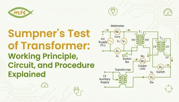
Take two identical transformers, call them T1 and T2. Their primary windings are connected in parallel and connected directly to normal rated supply voltage and frequency, exactly as they would be in real operation. So far, this is nothing unusual.
An interesting part happens on the secondary side. secondary windings of T1 and T2 are connected in series, but with their polarities deliberately opposed to each other. In plain terms, voltage induced in one secondary winding is arranged to cancel out voltage induced in another.
Since both transformers are identical, their induced secondary voltages are equal in magnitude. When you connect them in opposition, those two equal and opposite voltages cancel each other out almost perfectly. net voltage around that secondary loop becomes zero.
Before starting the test, this connection has to be verified. Engineers do this by taking two secondary terminals and joining them together, then measuring voltage across the remaining two terminals with a voltmeter. If that voltmeter reads zero, secondaries are correctly connected in phase opposition, and setup is ready. If voltmeter instead reads a value close to double rated secondary voltage, it means connections are wrong and need to be reversed.
Two wattmeters are placed into this circuit to do actual measuring. One wattmeter sits on the primary side and records power drawn from the main supply. A second wattmeter is placed in the secondary loop, and it comes into play once an additional small voltage is deliberately injected into that loop using a low voltage regulating transformer or auto transformer.
Why Secondary Voltage Cancels Out (Physics Behind It)
It is worth pausing here, because most resources simply state that secondary voltages cancel without really explaining why that matters.
When primaries are energized and secondaries are left open (before any voltage is injected), a small no load current flows in each primary winding. This current exists purely to set up magnetic flux in each core and to supply core’s iron losses. Since two transformers are identical, this no load current is the same in both.
Because secondary voltages are equal and opposite, no current flows around the secondary loop at this stage. This means the secondary is effectively acting as an open circuit, even though it is physically a closed loop. In other words, this initial condition is quietly simulating the exact same situation as an open circuit test, just using two transformers instead of one.
wattmeter on the primary side, at this stage, is reading power needed to supply combined iron losses of both transformers, since there is no copper loss contribution worth mentioning (no load current is very small). This gives you: iron loss per transformer equals half of this first wattmeter reading.
Simulating Full Load Without Wasting Full Load Power
This is the part that makes Sumpner’s test genuinely clever, so it deserves a slow explanation.
Once no load reading is taken, a small additional voltage is injected into the secondary loop using a regulating transformer. This injected voltage is gradually increased until current flowing in the secondary loop reaches the rated full load value.
Because of the way transformers work, this rated secondary current automatically causes a corresponding rated current to flow in primary windings too, through normal transformer action. So now, both primary and secondary windings of both transformers are carrying their full rated current, exactly as they would under genuine full load operation in the field.
Here is key insight: injected voltage only needs to be large enough to overcome internal impedance drops of two transformers and push rated current around that loop. It does not need to supply any actual output power to a load, because there is no external load connected at all. transformers are essentially just pushing current back and forth between themselves.
This means the second wattmeter, placed in this secondary loop, is now recording combined full load copper losses of both transformers, and almost nothing else. This reproduces the same full-load copper loss conditions measured during a short-circuit test, but allows rated current to flow continuously for heat-run observations.
Since real rated current and real rated flux are now present simultaneously in both transformers, exactly as they would be in normal service, this test also produces genuine, reliable heating. This is why Sumpner’s test can safely be run for extended periods, often for several hours, or as specified by applicable testing standards and manufacturer procedures, with oil or winding temperature checked periodically, to determine the transformer’s actual full load temperature rise.
Calculating Losses, Efficiency, and Voltage Regulation
Let’s turn readings into numbers, since this is where most exam questions and lab reports focus.
If the first wattmeter (on the primary side, at no load) reads W1, this represents combined iron loss of both transformers. So iron loss for a single transformer is:
Iron loss per transformer = W1 / 2
If the second wattmeter (in secondary loop, at full load current) reads W2, this represents combined full load copper loss of both transformers. So copper loss for a single transformer is:
Copper loss per transformer = W2 / 2
Once you have both losses for a single transformer, calculating efficiency at full load becomes straightforward using standard efficiency formula:
Efficiency = Output / (Output + Iron loss + Copper loss)
Where output is simply the transformer’s rated kVA multiplied by load power factor.
A Worked Example to Make This Concrete
Suppose two identical 100 kVA, single phase transformers are tested using a back to back method. primary wattmeter W1 reads 1,000 W, and secondary loop wattmeter W2 reads 1,800 W at full load current.
Step one, find individual losses: Iron loss per transformer = 1,000 / 2 = 500 W Copper loss per transformer = 1,800 / 2 = 900 W
Step two, calculate output at full load and unity power factor: Output = 100 kVA × 1.0 = 100,000 W
Step three, apply efficiency formula: Efficiency = 100,000 / (100,000 + 500 + 900) Efficiency = 100,000 / 101,400 Efficiency ≈ 98.62%
This tells you that each transformer is expected to run at about 98.62% efficiency at full load, unity power factor, based purely on readings taken without ever connecting either transformer to a real load. That is the entire value of this test in one calculation.
The test also provides the information needed to estimate voltage regulation by using the measured losses together with the transformer’s equivalent circuit parameters, combined with load power factor.
Sumpner’s Test vs OC and SC Test: A Quick Comparison
Students often confuse how Sumpner’s test relates to more commonly taught OC and SC tests. Here is how they actually differ.
| Aspect | OC Test | SC Test | Sumpner’s Test |
| Transformers needed | One | One | Two identical units |
| Gives iron loss | Yes | No | Yes |
| Gives copper loss | No | Yes | Yes |
| Simulates true full load heating | No | No | Yes |
| Duration | A few minutes | A few minutes | Can run for hours (heat run) |
| Power drawn from supply | Very low | Very low | Very low, despite full load current flowing internally |
| Real full load current present | No | Yes, during the test | Yes, continuously |
Advantages and Limitations You Should Actually Understand
Every method has trade offs, and Sumpner’s test is no exception.
On the advantage side, the biggest win is the economy. You get genuine full load current and flux conditions in both transformers while drawing only a small amount of actual power from supply mains, since most of the energy simply circulates between two units. This also makes it one of few practical ways to study true heating behavior of large power transformers, which would be prohibitively expensive to test using an actual load bank.
On the limitation side, the most obvious constraint is need for two identical transformers. For mass produced distribution transformers, this is rarely a problem, since manufacturers produce many identical units on the same line. But for large, custom engineered power transformers built for a specific project, finding a perfectly matching second unit can be difficult or impossible. Another limitation is that this test is primarily suited to single phase transformers or symmetrical three phase setups, and adapting it for certain three phase configurations requires additional care with phase sequence and connection groups.
Where This Fits Into India’s Growing Power Sector in 2026
Understanding Sumpner’s test is not just about clearing an exam question. It reflects a genuinely active part of India’s electrical engineering ecosystem right now.
India’s transformer market is expected to grow from roughly USD 3 billion in 2025 to USD 3.25 billion in 2026, with rapid grid modernization, rising peak power demand, and large government funding all driving this expansion. Peak electricity demand in India has jumped from 130 GW in 2014 to 243 GW in 2024, and it is projected to cross 400 GW by 2030, which means an enormous number of new transformers need to be manufactured, tested, and commissioned across the country in coming years.
Large transformers rated above 100 MVA are projected to grow at nearly a 9.75% CAGR between 2026 and 2031, outpacing smaller categories, and these are exactly units for which full load load bank testing is impractical, making back to back testing methods like Sumpner’s test genuinely relevant in real testing bays, not just textbooks.
Major manufacturers driving this growth include BHEL, which specializes in extra high voltage transformers up to 765 to 800 kV for national transmission grids, along with Siemens Energy India, CG Power, Voltamp Transformers, and Transformers and Rectifiers India Limited (TRIL), which supports ultra high voltage projects up to 1,200 kV including HVDC applications. These companies maintain dedicated testing infrastructure where efficiency, regulation, and heat run testing form a core part of quality assurance before a transformer ever reaches a substation.
Career Relevance: Why This Topic Matters for Your Future
If you are studying electrical or electronics engineering in India, this is exactly the kind of concept that shows up repeatedly, both in exams and on the job.
For competitive government exams, transformer testing methods including Sumpner’s test are a recurring topic in SSC JE, RRB JE, various state discom JE recruitment exams, and GATE Electrical Engineering. Questions typically test whether you understand wattmeter logic (which reading gives iron loss, which gives copper loss), reasoning behind series opposition, and basic efficiency calculations, exactly the kind of understanding this blog has walked you through step by step.
Beyond exams, there is genuine job relevance too. POWERGRID, a Maharatna PSU, regularly recruits Diploma Trainees and Junior Engineers whose responsibilities include maintenance, inspection, and operation of transmission lines and substations, involving real field work with transformers and switchgear. Testing and quality engineers at manufacturers like BHEL, Siemens India, CG Power, and TRIL work directly with transformer testing procedures, including heat run tests derived from same principles covered in Sumpner’s test, as part of manufacturing quality checks before transformers are shipped to utilities.
Typical entry points for freshers include roles like Graduate Engineer Trainee, Junior Engineer, or Testing Engineer at transformer manufacturing units and power utilities, with indicative starting salaries vary by employer, location, qualification, and role, with many entry-level positions in the range of 3–6 LPA at PSUs and private manufacturers, depending on role, location, and whether position is diploma level or degree level. Relevant disciplines include Electrical Engineering, Electrical and Electronics Engineering, and Power Systems specializations, and useful skills to build alongside this theoretical knowledge include familiarity with wattmeters, CT and PT connections, dissolved gas analysis basics, and standard transformer testing protocols.
Common Mistakes Students Make With This Topic
A few misunderstandings come up repeatedly, so it is worth addressing them directly.
The first mistake is assuming that Sumpner’s test can be performed on any two transformers of similar size. In reality, transformers must be truly identical in rating, turns ratio, and impedance for voltage cancellation and current simulation to work correctly. Even small mismatches introduce circulating currents that distort readings.
The second mistake is confusing which wattmeter measures which loss. Remember sequence: wattmeter connected on primary side, taken before any voltage is injected into secondary loop, gives you iron loss. wattmeter in the secondary loop, taken after injecting voltage until rated current flows, gives you copper loss. Getting this order backwards is one of the most common errors in exam answers.
The third mistake is forgetting to divide wattmeter readings by two. Since both wattmeters are reading combined losses of two transformers, not one, always divide by two to get loss for a single unit before applying the efficiency formula.
Wrapping It Up
Sumpner’s test solves a real, practical engineering problem: how to observe genuine full load behavior in a transformer, including realistic heating, without wasting enormous amounts of power that a true load bank test would require. By connecting two identical transformers so their secondaries cancel each other’s voltage and then injecting just enough current to simulate full load, engineers get accurate iron loss, copper loss, efficiency, and temperature rise data using only a fraction of actual full load power.
This concept sits at the intersection of exam preparation and real industry practice in India. Whether you are revising for GATE, preparing for an SSC JE or discom recruitment exam, or starting your career at a transformer manufacturing or power utility company, understanding not just formulas but underlying reasoning behind Sumpner’s test will serve you far better than memorization alone. Go back through worked examples in this blog, try recreating calculations with different wattmeter readings, and the concept will stick with you long after the exam is over.
FAQs
Sumpner’s test, also called back to back test, is used to determine a transformer’s iron loss, full load copper loss, efficiency, voltage regulation, and temperature rise under real full load conditions, without connecting an actual external load.
It gets this name because two identical transformers are connected back to back, with primaries in parallel and secondaries in series opposition, so that one transformer effectively loads another instead of using an external load bank.
No. Sumpner’s test specifically requires two identical transformers of same rating, turns ratio, and impedance, because the test relies on their secondary voltages canceling each other out to simulate loading conditions.
Iron loss (or core loss) occurs in the transformer core due to changing magnetic field and stays present whenever the primary is energized, even without load. Copper loss occurs in windings due to current flow and increases with load, reaching its maximum value at full load, which is exactly what Sumpner’s test measures.
Main limitation is requirement for two identical transformers, which is often unavailable for large, custom built power transformers, since these are frequently manufactured as one off units for specific projects rather than in identical pairs.
Yes. It remains a regularly tested topic in GATE Electrical Engineering, SSC JE, RRB JE, and state discom recruitment exams, and it reflects real testing practices used by Indian transformer manufacturers and utilities amid country’s ongoing grid expansion and rising transformer demand.